1
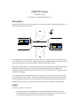
COMP2121 Project
Semester 1, 2011
Due Date: 3rd June (Friday of Week 13)
Description
The goal of the project is to use the AVR board to simulate a single lane bridge with boom gates. The
following picture describes the scene:
The bridge allows an East-West road to traverse a river, but is narrow and only allows traffic to cross
in one direction at a time. To ensure adequate traffic flow, boom gates have been installed at either
end of the bridge to ensure only one direction of traffic has access at any time.
Boom gate A blocks traffic in the eastbound direction from entering the bridge. Boom gate B blocks
traffic in the westbound direction from entering the bridge. Additionally, the bridge has an
emergency stop switch to stop both lanes of traffic in case of an accident or if an emergency vehicle
needs to use the bridge.
It is assumed that the average length of each car and the space around it is 5 meters, and the space
taken by the gates is also 5 meters. The bridge is equipped with pressure sensors placed 12 meters
from either gate to detect the arrival of cars. When a car is 10 meters away from either gate, then
the gates will know that a car is approaching. Cars are travelling at a speed of 5 meters/second.
Inputs
Inputs to the system are as follows:
•
Pushing a number on the keypad followed by A or B indicates the number of vehicles
approaching the named boom gate (e.g., pushing 4 then A indicates a queue of 4 vehicles
arriving at boom gate A). See Interface section for more clarification.
•
Pushing and holding one of the push buttons indicates the emergency situation. The
emergency situation remains in place until the button is released.
Protocol
The boom gates and vehicles should operate under the following protocol:
•
•
•
•
•
•
•
•
•
•
At startup, you may assume no vehicles are in the vicinity of the bridge.
Whenever there are no vehicles waiting at either side of the bridge, both boom gates will
close.
If there are vehicles on only one side of the bridge, the boom gates will transition to let that
direction of traffic through. If a boom gate is open, vehicles will enter the bridge through
that boom gate.
The length of the bridge is 25 meters.
To alleviate congestion, if one gate has been open for at least 7 seconds and there is a car
waiting at the other boom gate, then the current boom gate will close and the other boom
gate will open.
A boom gate will not begin opening while there are vehicles still on the bridge travelling in
the other direction.
Boom gates take 2 seconds to open and 2 seconds to close. Vehicles should not pass while
they are opening or closing.
When the emergency switch is pushed, boom gates will start closing immediately. However,
the vehicles already on the bridge will continue as normal.
In an emergency, boom gates will remain shut until the push button is released.
Vehicles can still arrive at either end of the bridge during an emergency.
Interface
The following features must be present in the interface, although you are free to add additional
information:
•
•
The first line of the LCD must sketch the state of the bridge:
o Assume each character of the LCD represents a 5 meter space.
o Character locations 1 – 5 represent the cars waiting at boom gate A.
o Character location 6 represents the boom gate A.
o Character locations 7 – 11 represent the bridge.
o Character location 12 represents the boom gate B.
o Character locations 13 – 16 represent the cars waiting at boom gate B.
o The pressure sensors will be at character locations 3 and 15.
o Arrival of the cars at either side of the bridge and their traversal of the bridge must
be simulated according to the above specifications. For example, if 4A is pressed
then a queue of 4 cars should start appearing at character location 1 on the first line
of the LCD and continue until they leave the bridge.
The second line of the LCD must be able to display:
o The number of vehicles waiting on the boom gate A side of the bridge
o The number of vehicles waiting on the boom gate B side of the bridge
•
•
o The number of vehicles currently traversing thebridge
o The state of both boom gates (open, closed, opening, closing)
o The direction of the cars travelling on the bridge.
The motor will run at 80rps whenever either gate is opening and at 50rps when either gate is
closing.
Two LEDs should operate as traffic lights (red only) for the boom gates. They will switch off
when the boom gate is open, indicating traffic may go. During an emergency, both LEDs will
blink at a rate of 3 Hz (3 blinks per second).
Bonus
The following bonus feature can be impemented, but is not required to receive full marks for the
project. In the case that the emergency button is pushed while a boom gate is opening, then the
boom gate should properly simulate the amount of time it will take to close. E.g., if the gate had
been opening for a quarter of a second, it should only take a quarter of a second to close.
Submission information
The following items should be submitted:
1. Source code via the subject webpage, and its printed copy. Your program should be well
commented.
2. A printed copy of a user manual. The user manual describes how a user uses your bridge
emulating system, including how to wire up the AVR lab board. Make sure you indicate
which buttons perform each action and how the LED and LCD displays should be
interpreted.
3. A printed copy of the design manual. The design manual describes how you design the single
lane bridge emulating system. It must contain the following components.
a. System control flow, describing the control flow of the system at the module level
using a diagram. This also shows how and when you service the inputs.
b. Data Structures, describing the main data structures used in the system.
c. Algorithms, describing how you keep the state of the bridge and vehicles.
d. Module specification, describing the functions, the input and the output of each
module.
Overall, a person with knowledge about the subject and board should understand how your system
is designed after reading this design manual.
Assessment of your project working on the AVR board will also be performed in week 13.
Grading
The project is worth 15% of your course mark and will be marked under the following criteria (which
is approximate for now):
•
Implementation (65%):
o Adherence to specification
o Implementation of all input/output functionality
•
•
•
Code Style (10%):
o Easy to read
o Well documented
User Manual (10%)
o Accurately describes set up of board
o Correctly describes functionality
Design Manual (15%)
o Adherence to specification
o Readability and Completeness