1
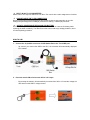
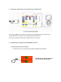
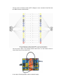
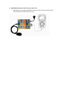
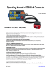
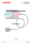
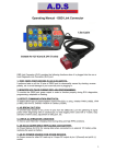
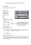
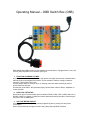
Operating Manual – OBD Switch Box (OSB)
OBD Switch Box (OSB) provides you the following functions when it is plugged into the car (12V)
or truck (24V) Diagnostic Link Connector (DLC) port.
1. FUNCTION AS BREAK OUT BOX
Any tools such as lab scopes, multimeter, logic probes, test lights etc that uses a standard 4mm
banana plugs can be plugged to this device 16 pins sockets to read the voltage, resistance,
frequency, pulse width or duty cycle.
Use the jumper cable for direct pin to pin or stacking connection while scanning or perform
special functions and tests.
Use the blink Code Cable - N/O (Normally Open) contact switch cable for Reset, Adaptation or
codes activation.
2. PROTOCOL DETECTOR
Detect which type of communication protocol whether PWM (J1850), VPW (J1850), ISO 9141-2,
DIS/ISO 14230-4 or Canbus (J-2284).and monitor data stream being used when connecting the
scan tool to the car OBDll ports.
3. VOLTAGE METER DISPLAY
It monitors voltage constantly during reflash programming due to prolong time and power
consumption.
Also to check Alternator charging condition during idling and high RPM conditions
4. BUILT- IN 24V TO 12V CONVERTER
Switch 24V to 12V output so that some 12V Scan Tool can be also used to diagnose truck vehicle.
5. CHANGE CABLE PIN TO PIN CONNECTION
Disconnect the entire pass through16 pins and change to any pin-out connection as you like.
Change the pins assignment of OBD (M) connector to OBD (F) or DB25 (M) connector.
6. AS DATA SAVER WHILE REPLACING CAR BATTERY
As Power Backup for ECU (for saving data) when connected to an external 12V battery while
replacing the weak car battery. The data-saver cable comes with surge voltage protection, short
circuit and polarity protection.
HOW TO USE:
1. Connect the 16 pin Male connector of OBD Switch Box to the Truck OBD port.
-
As soon as you connect the OSB to the DLC, the voltmeter will automatically displayed
ECU voltage.
2. Press the switch ON to Convert the 24V to 12V output.
-
By pressing the switch it will automatically converted from 24V to 12V and the voltage will
also shows on the OBD F voltage monitor.
3. Connect the 16 pin Female connector Pass-Thru to the Scan tool.
The 16 pins of OBD male connector are connected to all 16 banana sockets on the LEFT side,
and the OBD female connector to the 16 banana socket on RIGHT side.
And all the 4 mm banana socket (LEFT & RIGHT) are inter connected.
4. Change the pins assignment of the OBD M&F connector.
4.1 Disconnect the 16 pin connection.
-
To disconnect the 16 pin connection by pressing the OBD Switch Box Switch.
The LED will turn ON, to indicate the
entire 16 pins are disconnected.
-
Then the entire 16 banana socket (LEFT & Right) no more connection Pass-Thru both
the OBD Connector male & female.
-
Use the jumper cable or the stacking banana cable insert it to the banana socket to
connect any pins you may wish to use.
-
-
It has 16pcs of Stacking Banana cable as standard supply.
5. With DB25 M Connector Pass-Thru to the Scan Tool.
-
OBD Switch Box is provided with DB25 M connector so that it can be connected to BD
connector apart from OBD Female connector.