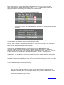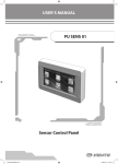
1
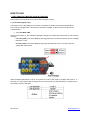
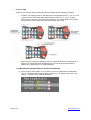
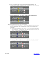
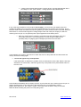
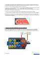
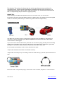
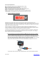
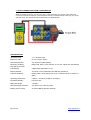
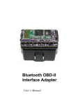
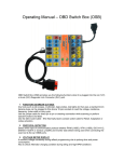
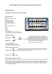
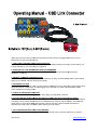
OBD Link Connector (OLC) provides the following functions when it is plugged into the car or truck
Diagnostic Link Connector (DLC) port:
1. TEST OBD2 PORT BEFORE PLUG IN SCANTOOL
It performs tests on all the 16 pins of OBD2 port for abnormality caused by shorting, reverse polarity, etc
to avoid damage to your scan tool prior plugged in.
2. MONITOR VOLTAGE DURING REFLASH PROGRAMMING
To monitor the OBD2 port power output in order to function properly during ECU programming,
adaptation or flashing
3. DETECT COMMUNICATION PROTOCOL
To detect which type of communication protocol the ECU is using, whether PWM (J1850), VPW (J1850),
ISO 9141-2, DIS/ISO 14230-4
4 or Can bus (J-2284).
(J
4. AS BREAK OUT BOX
To provide easy access to any of the 16 pins
pins from the OBD2 DLC port for gathering of signal pulses when
diagnosing with an oscilloscope, for data logging when used with a Y-cable,
Y cable, easy activation of blink
codes, adjustment of idling rpm,etc
5. CHECK ALTERNATOR CONDITION
To have a quick Alternatorr charging check during idling and high RPM conditions.
6. As Power Backup for ECU (Keep Alive Memory (KAM) chip) while replacing car battery
For the last 10 to 15 years, car ECUs were designed to have Keep Alive Memory (KAM) chip that allows it
to maintain normal vehicle performances by compensating for sensors and parts wears. This KAM chip
needs power to store all the Data gathered and it will lost if power is disconnected. Therefore it is
essential to provide power to the ECU while replacing the car battery.
7. AS DC POWER SOURCE FOR OTHER DEVICES
As Power source for other DC loads up to 5 Amps DC output at pin 4 (Ground) and pin16 (+) Socket.
AE Tool Ltd.
www.aetool.com
HOW TO USE
1. TEST OBD2 PORT BEFORE PLUG IN SCANTOOL
Test is carried out with ignition key is OFF, ON and engine running
1.1 Test without Ignition Key
Connect the OLC to the OBD2 port on vehicle. The testing of the DLC port starts automatically as
soon as OLC is plugged into it. This test is to check the condition of all pins before the ignition key
is switched ON.
1.1.1 Volt Meter LED
As soon as it powers up, the voltmeter will display voltage input. Notice the alarm beeps on the following
condition.
For 12V system: The alarm ‘Beeping’ will trigger ON (one at a time for 30 sec) when the voltage
falls below 11.8V.
For 24V system: The alarm ‘Beeping’ will trigger ON (twice at a time for 30 sec) when the
voltage falls below 23.8V.
When the battery falls below 11.8V for 12V system or 23.8V for 24V system, the alarm will come on. In
this case, you may need to start the engine to run for some time to charge the battery or replace with a
new battery and then test again.
AE Tool Ltd.
www.aetool.com
1.1.2 Pins LED
Testing of the 16 pins individually will also begin immediately with the following conditions
•
To detect any voltage present on Car Manufacturer designated pins No.1, 3, 8, 9,11,12 &
13 (yellow colour socket) and OBD2 assigned protocol pins 2, 6, 7, 10, 14, 15 (blue
colour socket), other than pins 4(Chassis), 5(Signal) for grounding (black colour socket)
and pin 16 (red colour socket) which is positive supply 12V or 24V.
•
When there is a presence of voltage (positive or negative) detected at a particular pin or
other pins on the Manufacturer designated ones, the LED at the socket will blink in
different ways. Depending on the voltage detected:
1.1.3 Manufacturer Designated Pins (Yellow Color Socket)
a)
AE Tool Ltd.
If there is 12V present (below 11.8V or above 15.2V) in any Manufacturer Designated
pins – the respective LED will blink slowly at interval of 1 sec between each blink. (The
‘Caution – Voltage present’ LED will illuminate).
www.aetool.com
b) If there is a negative voltage present in any Manufacturer Designated Pins – the
corresponding LED will light steady. (The ‘Caution – Voltage present’ LED will illuminate).
c) If there is 24V present (below 23.8V or above 29.2V) in any Manufacturer Designated
Pins– the LED will blink fast. (The ‘Caution – Voltage present’ LED will illuminate).
OBD2 Assigned Protocol Pins (Blue Color Socket)
• In the event when there is a presence of voltage detected at OBD2 Designated Protocol
Pins, the respective LED in the socket will blink in different ways with corresponding
alarm beeps.
a. If there is 12V present (below 11.8V or above 15.2V) – the respective LED will blink
slowly at interval of 1 sec between each blink with a short beep alarm for 5 sec. (The
‘Caution – Voltage present’ LED will illuminate).
b. If there is a negative voltage present – the corresponding LED will light steady with a
long beep alarm for 5 sec. (The ‘Caution – Voltage present’ LED will illuminate).
AE Tool Ltd.
www.aetool.com
c.
If there is 24V present (below 23.8V or above 29.2V)– the LED will blink fast with a
loud beep for 5 sec. (The ‘Caution – Voltage present’ LED will illuminate).
If any of the above situations is encountered, do not plug in your Scan tool yet. Please check and
compare the OBD2 circuit connection with vehicle Repair Manual for the reason of the shorting. This is
because under normal circumstances when the ignition key is OFF, the ECU is also in the OFF state and
there will be no communication signals or voltage output to the rest of the pins except pin 4 which is
chassis ground and pin 16, the positive power output supplied from the battery direct.
•
With very remote chance unless the connections has been tampered, when OLC
encounters that there is a reversed polarity occurred the green LEDs at pin 4
(Chassis) and pin 5 (Signal) ground will light up and turns into red colour.
In this situation do not plug in the Scan tool. Check the source of the problem at the vehicle DLC and
rectify it first before testing again.
1.2 Test with ignition key in ON position.
If the first test did not indicate any problem, then proceed with the second test. With the OLC still
attached to the vehicle DLC, switch the ignition key to ON position then press Restart button on
the OLC once.
The test starts immediately with the testing of all the 14 pins other than pin 4 chassis ground and pin 16
positive Voltage supply. At the same time it will detect the type of communication protocol
(PWM, VPW, ISO 9141-2, ISO 14230-4, CAN H, and CAN L) that the ECU is using and the blue
LEDs will blink indicating the protocol currently being used.
AE Tool Ltd.
www.aetool.com
If any voltage present on vehicle Manufacturer designated pins No.1, 3, 8,9, 11, 12 & 13 (yellow
colour socket) other than OBD2 assigned protocol pins 2, 6, 7, 10, 14, 15 (blue colour socket) and
5(Signal ground), the corresponding LED will light in the following manners.
•
If there is 12V present– the LED will blink slowly at interval of 1 sec between each blink.
(The ‘Caution – Voltage present’ LED will illuminate).
•
If there is 24V present – the LED will blink fast. (The ‘Caution – Voltage present’ LED will
illuminate).
In situation where there is 12V or 24V present at the pin, the voltage was either supplied direct short or
through a resistor. Its resistance value is normally not more than 20Ω.
However, when a voltage 0V is supplied from the other end of the Scan tool to this pin, a current bigger
than 0.6A will flow. This indication serves as a warning when using Scan tool without current limiter builtin because this voltage may damage it when plugged in.
In many cases, Vehicle Manufacturers do provide some pins on the OBD2 Diagnostic Link
Connector (DLC) at the vehicle for RPM signals or Sensors signals used for testing or adjustment.
These signals are usually found on any of the Manufacturer designated pins No.1, 3, 8, 9, 11, 12 &13 on
the DLC. Therefore such signals will be detected and indicated as “Caution – Voltage Present”.
In other words, you can still plug in and use your scan tool but with risk in case where the Scan tool has
no protection.
It is also important to note that the presence of voltage in one of the pins maybe one of the reasons why
sometimes communication failed between Scan tool and ECU because of the presence of the 12V or 24V
shorting.
However, almost all Scan tools nowadays come with protective current circuit and this indication should
not be accepted as danger but served as a warning.
1.3 Test with Engine running
When the second test has completed, proceed with the third and final test. With the OLC still
attached to the vehicle DLC, start and keep the engine running. Press the Restart button on the
OLC. The test starts and it will repeat as in the second test but this time it will test for over 15V or
29V presence while the engine is running.
AE Tool Ltd.
www.aetool.com
If the voltage is higher than 15.2V for 12V system or 29.2V for 24V system, the alarm will also come on.
In this situation, the problem was caused by the regulator which had failed to regulate and cut OFF after
reaching the preset charging voltage limit normally set below 15V.
Also, if over 15.2V for 12V system or 29.2V for 24V system was detected at the input or any of the vehicle
Manufacturer designated pins No.1, 3, 8, 11, 12 & 13 (yellow colour socket) other than
OBD2 assigned protocol pins 2, 6, 7, 10, 14, 15 (blue colour socket) the LED will blink at a very fast pace.
(The ‘Caution – Volt present’ LED stays ON).
In this case, do not plug and test with the Scan tool while engine running as this high voltage
input may damage it. Check the charging volts to determine whether the regulator is functioning properly.
Under normal conditions when after all the testing of the vehicle DLC port has been done, where there
are no abnormal activities, the green ‘OK’ LED will light up. This indicates everything is OK and it is ready
for Scan tool to be plugged in
2. MONITOR VOLTAGE DURING REFLASH PROGRAMMING
It has voltage monitoring feature with Volts display which will give an alarm warning when the voltage falls
below 11.8V or higher than 15.2V (for 12 V System) or below 23.8V or higher than 29.2V (for 24V system)
while doing programming or coding. This feature will minimize any error while performing EPROM re-flashing.
AE Tool Ltd.
www.aetool.com
3. DETECT COMMUNICATION PROTOCOL
To monitor data stream and protocol being used when connecting the scan tool to the car OBD ports via
OBD Link connector (OLC)
LEDs Activities:
OBD Link Connector LEDs allows you to keep taps on power and ground. It identifies the protocol used in
the vehicle.
1. RED LEDs (Pin 16) - automatically turn-on as soon as you plugged into DLC. RED LEDs turn dim
when:
Low battery voltage - refer to Voltmeter and alarm will beep (below 11.8V for 12V system and
23.8V for 24V system). Wiring to DLC pin 16 is faulty. Grounds circuits have resistance issues.
2. GREEN LEDs (Pins 4 – Chassis and 5 - Signal) - automatically turn-on as soon as you plugged
into DLC. Ground LED (Pin 5) is connected to battery voltage via ECU. Therefore, a ground
supply on pin 4 will not affect LED 5. A dim single green LED will indicate a circuit problem with
the corresponding circuit. In remote case where if there is reverse polarity; the Green LED will
turn into RED colour. When this happens, check the vehicle DLC connector for wrong polarity.
Rectify first and test again.
3. BLUE LEDs (Pins 2, 6, 7, 10, 14 and 15) - LEDs should flash when serial data voltage pulses are
present in the data line.
Blue LEDs is assigned on pins 2, 6, 7, 10, 14 and 15 to indicate communication with scan tool or
interface and for communication protocol identification. It will turn-on depend on your vehicle
model. For some vehicle model, one or multiple blue LEDs will turn-on as soon as the OBD Link
Connector is connected and you start the ignition. The brightness of the LEDs depends on the
nature of the signal it's pursuing. This OBD Link Connector can identify immediately the protocol
used. The better way to identify the protocol in use is to set-up the scan tool or interface in to
LIVE DATA. This will lead in a constant data stream between the scan tool and the vehicle, and
then you can locate the LEDs that are flashing.
4. YELLOW LEDs (Pins 1, 3, 8, 9, 11, 12, and 13) - it should flash when your vehicle manufacturer
use either one on the pins for any function they prefer.
Pin Assignments
Pin #
12345678910 11 12 13 14 15 16 -
AE Tool Ltd.
SAE Designation
Discretionary
Bus + Line of SAE J1850 (PWM/VPW)
Discretionary
Chassis Ground
Signal Ground
CAN High of SAE J2284 (ISO 15765-4)
K Line ( ISO 9141-2 and ISO 14230-4)
Discretionary
Discretionary
Bus-Line of SAE J1850(PWM)
Discretionary
Discretionary
Discretionary
CAN Low of SAE J2284 (ISO 15765-4)
L Line (ISO 9141-2 and ISO 14230-4)
Unswitched Vehicle Battery Positive
www.aetool.com
Pins listed as "Discretionary" indicate that the vehicle manufacturers may used them for
specified purpose. Check with the manufacturer's specifications for these connections. For
voltage and current limits, refer to SAE J1962 (ISO 15031-3.3). Test tool must not draw more
than 1.5 amps through the pin number 5 (Signal ground).
Helpful Tips:
When activating some ABS and diagnostics wires to recover flash code, you can use pin 4.
If red (power) and green (grounds) LEDs turned dim or flickering when you plugged a scan tool supplied
via DLC, it indicate a problem with your vehicle wiring that causes the voltage to drop.
4. AS BREAK OUT BOX
This OBD Link Connector (OLC) is a pass-through breakout box for the OBDII DLC (diagnostic link
connector). It can be connected to your OBD-II compatible tools: such as scan tools, code readers,
monitor readers or data loggers.
Any tool that uses a standard test lead or probe that use 4mm banana plugs (including those with safety
heaths) can be plugged to OLC’s 16 pins sockets, these include, lab scopes, multi-meter, logic probes,
test lights, etc to read the voltage, resistance, frequency, pulse width or duty cycle.
Pin 16 sockets is protected by a self- recovery fuse rated at 5 amps
Jumper cable and Blink Code cables are standard accessory:
Jumper cable: for direct pin to pin or stacking connection while scanning or perform special functions and
tests.
Blink Code Cable - N/O (Normally Open) contact switch cable for Reset, Adaptation or codes activation.
AE Tool Ltd.
www.aetool.com
Some Typical Applications:
VW - To protect the Scan tool such as aftermarket radios on VW's
GM - Transmitter Programming on some GMs
Honda - Set the ECM in SCS mode with your scan tool connected
Lexus - Help diagnose electronics systems (Sirius, GPS) on pin 6 and 14
Bosch - Troubleshoot Bosch controllers that short to ground
Proton - needs to short pin 1 to ground in order to access into OBD2 functions.
Toyota Avanza - the base RPM can only be achieved by shorting pin 4 and 12
5. CHECK ALTERNATOR CONDITION
With ignition key in OFF position; plug OLC into the car DLC without connecting the scan tool.
Switch key to ON position and the volt LED will display the battery voltage. Start the engine; observe the
voltage display while the engine is idling. It should be above 12.6 Volts for 12V system or 25.2V for 24V
system. If not, check for loose drive belt.
Then rev engine up to 3,000rpm and observe the change in voltage. If the voltage is above 15.2
Volts for 12V battery or 29.2V for 24V battery, the alarm will beep indicating that the charging voltage is
too high. In this case, the regulator may be faulty and it needs to be checked.
Then switch ON all electrical loads, rev engine to 2,000rpm and observe the changes in voltage at the
tool. The voltage should above 13.6 Volts for 12V system and 27.6V for 24V system. If the voltage is
below, check for loose drive belt and the Alternator
6. As Power Backup for ECU (Keep Alive Memory (KAM) chip) while replacing car battery
Connect the OBDII cable with battery clips to OLC. Turn ignition key to OFF position and connect
the tool to the car DLC. Attach the battery clip to an external battery (not the battery from the
same car). If the external battery voltage is above 12V, the battery volt indicator LED on the Data
saver cable will light up. Now it is ready to proceed for replacing the car battery.
After job done, remove the battery clips from the external battery, unplug OLC from the car.
The data saver cable comes with surge voltage protection, short circuit and polarity protection.
AE Tool Ltd.
www.aetool.com
7. AS DC POWER SOURCE FOR OTHER DEVICES
While connected to the DLC, you can tap +12V or +24V depending on the power input at the DLC
connector red banana socket (pin 16) and Chassis Ground (-) at black banana socket (pin 4) to power
other DC loads. This voltage will also be displayed on its digital display.
SPECIFICATIONS
Operating range:
7.0 ~ 30.0VDC Input.
Maximum Load:
Up to 5.0 Amps. Output.
Overload Protection:
Yes- PTC Fuse (Self-healing)
Monitoring Voltages:
stop after 30 seconds.
Beeper ON: below 11.8V, between 15.2 to 24V, higher than 28V. Beeper
Volt Displays:
3 Digits LEDs (Resolution: 0.1V)
Banana Sockets:
16 outputs x 4.0mm diameter with LED lamp indications.
Protocols Detected:
PWM (J1850), VPW (J1850), ISO 9141-2, DIS/ISO 14230-4, Canbus (J2284).
Operating temperature:
0 Deg.C ~ 50 Deg.C (32 Deg.F~122 Deg.F)
Permitted Humidity:
Less than 70%.
OBD cable length:
1.5 meter
Reverse Polarity protection:
Yes, LED on pin 4 & 5 turns Red
Battery used on Lamp:
3V Lithium Battery (Model: CR1220)
AE Tool Ltd.
www.aetool.com