1
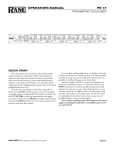
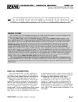
OPERATING / SERVICE MANUAL
MPE 28
MIDI PROGRAMMABLE EQUALIZER
QUICK START
Reading owners manuals is like eating vegetables—a nuisance which is necessary, at least according to your mother. It
ensures longevity and proper operation of your systems but chocolate soda is more fun. In the event you want to find a
short-cut we provide this section to help you avoid the spinach. At least read this and save the rest for later. And remember—clean your plate, people are starving somewhere.
Upon initial power-up, you should see the words, “Rane MPE 28...rX.X” (the current revision level) scroll by in
the SYSTEM display window. Then the SYSTEM display indicates the last memory location used before the power was
turned off, and the green MEMORY indicator lights. The MPE 28 is now ready to use.
(The MPE 28 has two levels of security lockout. If you think your unit may be in either of these lockout modes, please
consult the enclosed MPE Users Guide for further instructions.)
Two terms need to be learned early on. The first is Stored Memory. Stored Memory is any of the 128 locations provided
for curves. The second is Working Memory. Working Memory is a scratch-pad location used for changing curves before
you put them into Stored Memory. Working Memory is also what you hear.
The first few Stored Memory locations (programs 1 to 21) were preset at the factory. A table of these is in the MPE
Users GuideAppendix. In the beginning these give you instant curves for experimenting. If you want a different curve,
press the UP/DOWN buttons to scroll, or directly enter a Stored Memory number via buttons 0 through 9 (observe the red
SYSTEM display). Please note that all Stored Memory numbers must be at least two digits; e.g., Stored Memory number4
is entered as 04, etc. For direct access to Stored Memory locations above99, push the 100 button, then the next two digits.
For example, to recall Stored Memory125, press 100, 2 and 5, and you will have arrived! Once the last digit is entered,
the Stored Memory is instantly called up (what you see is what you hear).
Changing the overall level or equalizer curve requires the use of the EQ Edit mode. Push the EQ button (repeated
operation cycles between the first half of the frequencies, the second half and neither) to select the frequencies you wish to
modify. Now press LEVEL or the frequency button desired (the yellow LED lights). Next scroll the UP/DOWN buttons
until the desired level shows on the green EQUALIZER display. When finished editing, push the STORE button once,
enter a new Stored Memory number if needed, then push STORE again to place the new curve into the Stored Memory
shown on the red SYSTEM display. Presto facto, it’s Miller time. See the enclosed MPE Users Guide for futher details.
The MPE 28 presets can be recalled either by front panel or externally through MIDI. If you have a PC with a MIDI
interface, Rane can supply you with a DOS graphic editor program just for asking (no charge). If you have a Mac, see the
Galaxy Universal Librarian from Opcode Systems. Other software companies may have other librarians that will work. If
you would like to change presets with external switches, check out the Rane RPS 4 Remote Program Selector.
CAUTION: NEVER CONNECT ANYTHING EXCEPT RANE MODELS RS 1, RAP 10 OR FRS 8 AC POWER SUPPLIES
TO THE RED THING THAT LOOKS LIKE A TELEPHONE JACK ON THE REAR OF THE MPE 28. This is a low-voltage
AC power input and requires some special attention if you use anything except an approved Rane power supply.
SYSTEM CONNECTION
When connecting the MPE 28 to other components in
your system for the first time, leave the power supply for last.
This will give you a chance to make mistakes and correct
them before any damage is done to fragile components in the
system.
INPUT. The input on the MPE 28 is balanced/unbalanced.
This means that standard ¼" connectors on the ends of any
good quality cable will work well between your signal
sources, signal processing and amplification. If balanced ¼"
input is your choice, use a Tip-Ring-Sleeve connector; wire
the tip as hot (+), the ring as return (–), and the sleeve as
signal ground. The MPE 28 also gives you the opportunity to
use a 3-pin (XLR) input connector. Balanced operation
through this Input requires pin 2 be used as hot (+), pin 3 as
return (–), and pin 1 as signal ground. Unbalanced sources
require that pin 1 be connected to pin 3 on the Input connector only. Therefore, pin 2 is hot, pins 1 and 3 are signal
ground.
OUTPUT. The MPE 28 offers a similar choice of output
connector and the wiring is the same as far as polarity of pins
is concerned. When hooking up an unbalanced Output using
the 3-pin, disregard the italics in the preceding paragraph.
DO NOT connect pin 3 to pin 1. Leave it open, please. Thank
you.
You should be aware, also, that just because we indicate
that a sleeve on a ¼" or pin one on a 3-pin is used for grounding, it is not always wise to use it. Rane Note 110 (included
with your unit) goes into the reasons and logic behind all of
this madness. Please have a look at it to try to attain the best
performance possible from your MPE 28.
FRONT PANEL DESCRIPTION
1. BYPASS. Pressing this button toggles between Bypass and Active modes (LED on = BYPASS).
2. CURVE WEIGHT. The CURVE WEIGHT button weights curves; hammers let you hammer things and wrenches let you
wrench things. See the MPE Users Guide for details on summing two curves together.
3. STORE. Pressing this control transfers the contents of Working Memory into Stored Memory at a location selected by either
the number keys or the UP/DOWN buttons. Pressing STORE once prompts the user for the Stored Memory location;
pressing it again writes the information to Stored Memory.
4. OL. Overload (OL) indicator. This red LED illuminates any time the input, filters or output reaches 4dB below clipping.
5. EQUALIZER Display. This numeric green LED display indicates the boost/cut level of an individual filter, or the overall
Level, whichever is selected (LED on). The MPE 28 must be in the EQ Edit mode to activate this display.
6. EQ. Pressing this button once places the MPE 28 in the lower frequency EQ Edit mode (yellow LED on); a second depression enters the upper frequency EQ Edit mode (green LED on); and a third time takes the MPE 28 out of the EQ Edit mode
(both LEDs off).
7. LEVEL / EXPRESS. In the EQ Edit mode, this button sets the overall level of the equalizer. When not in the EQ Edit
mode, this button sets Expression parameters. Expression allows an EQ curve to “bend” (change) based on MIDI continuous
controller or channel pressure aftertouch commands. Please see the MPE Users Guide for further information.
8. 31.5Hz / 800Hz / BANK. In the EQ Edit mode, this button selects either the 31.5Hz or the 800 Hz filter. In the Normal
Operating mode, pressing this control locks the MPE to the current bank; something similiar to a “tens hold” function. When
using the octal numerical base system of notation instead of the decimal numerical base (explained in the MPE Users
Guide) it has a similar function.
9. 40Hz / 1kHz / 100 / OCTAL A/B. In the EQ Edit mode, this button selects either the 40Hz or the 1kHz filter. In the Normal
Operating mode this gets you directly to the 100s, or switches between A/B banks when using the octal numerical base.
10. 50Hz / 1.25kHz to 500Hz/12.5kHz. In the EQ Edit mode, these buttons select the filters associated with their labels. In the
Normal Operating mode they allow direct access number entry for Stored Memory selection. They also select several
secondary features when used with the FUNCTION button. To find out about their uses, please see the MPE Users Guide.
11. 630 / 16kHz / FUNCTION. In the EQ Edit mode, this button selects either the 630Hz or the 16kHz filter. In the Normal
Operating mode it acts as a shift-key to select the secondary features. Again we must reference the MPE Users Guide for
details. Sorry.
12. UP & DOWN. Used to increase or decrease parameters in all operating modes.
13. SYSTEM Display. This red digital display indicates system information, such as Stored Memory locations, MIDI Channel
selection, mapping assignments, lockout codes, Factory preset numbers, ramp step size, revision number, and so on.
14. MEMORY. Used to enter the Normal Operating mode. A flashing LED indicates Working Memory differs from Stored
Memory. When in the EQ Edit mode, all changes to the Working Memory are compared with the Stored Memory version by
simply pressing and holding the MEMORY button. What is heard is the Stored Memory curve; releasing the MEMORY
button allows you to hear edited Working Memory.
15. CHANNEL. Pressing this button displays the current MIDI Channel assignment for this MPE. Flashing indicates MIDI
OMNI mode is on. Change the MIDI Channel by using the UP/DOWN buttons, or number keys. Pressing this button again
returns the unit to Normal Operating mode.
16. MAP. Used for MIDI Mapping (re-routing program changes to memory locations) covered in the MPE Users Guide.
REAR PANEL DESCRIPTION
1. 3-Pin INPUT. Active balanced input: Pin 2 is (+), pin 3 is (–), pin 1 is signal ground, and the shell is chassis ground. For
unbalanced use, connect pins 3 and 1 together and drive pin 2.
2. ¼" INPUT. This is a tip-ring-sleeve (TRS) balanced input connector. Tip is (+), ring is (–), and sleeve is ground. For
unbalanced operation, use either a TS or TRS plug. If using a TRS plug, connect the ring & sleeve together.
3. 3-Pin OUTPUT. Active balanced output: Pin 2 is (+), pin 3 is (–), pin 1 is signal ground, and the shell is chassis ground.
4. ¼" OUTPUT. This is a tip-ring-sleeve (TRS) balanced output connector. Tip is (+), ring is (–), and sleeve is ground. For
unbalanced operation, use a TRS plug: connect your hot lead to the tip, ground to the sleeve and leave the ring open.
5. MIDI IN. This connector allows the MPE 28 to respond to external MIDI control.
6. MIDI OUT. This connector transmits MIDI Program Changes, etc., to the input of another MIDI device.
7. MIDI THRU. This output contains all the MIDI information exactly as it comes into the MIDI input. None of the controls
on the MPE 28 have any effect on this output. Normally used for daisychaining purposes.
8. Remote Power Supply Input. USE ONLY A RANE MODEL RS 1, RAP 10, FRS 8 OR OTHER REMOTE AC POWER
SUPPLY APPROVED BY RANE. The MPE 28 is supplied with a remote power supply suitable for connection to this input
jack. Consult the factory for replacement or substitution.
9. GROUND LIFT Switch. This switch gives the user the option to tie signal ground to chassis ground. Typically, a system is
quieter in the LIFT position. See CHASSIS GROUNDING note on last page for details.
10. Chassis Ground Point. A 6-32 screw is used for chassis grounding purposes. See CHASSIS GROUNDING note on last
page for details.
OPERATING INSTRUCTIONS
THE BASICS. Don’t be intimidated by the fact that the
MPE 28 is a programmable equalizer with a lot of buttons on
the front and none of the familiar slide controls and rotary
pots and such. The product is very straightforward and
following the steps below should get you started.
EDITING CURVES. Changing the overall Level or
equalizer curve requires the use of the EQ Edit mode. To edit
any curve, push the EQ button (repeated operation cycles
between the lower-half of the available frequencies, the
upper-half, and Off. Now press LEVEL or any of the 14
frequency buttons (the yellow LED lights to acknowledge
selection). Next scroll the UP/DOWN buttons until the
desired Level shows on the green EQUALIZER display.
When finished editing, push the STORE button once. The
number in the SYSTEM display starts blinking to remind you
to select a location, or to use the current one. Enter a new
number if needed, then push STORE again to place the new
curve into the Stored Memory location shown. The MPE
Users Guide should be consulted for further details.
STORING CURVES. Any curve may be stored in any or
all of the 128 memory locations. Once stored, this location is
referred to as the Stored Memory location. To begin the
process, press STORE once. This causes the SYSTEM
display to begin blinking the current Stored Memory location
number. If you want to store your Working Memory curve
into this location, press STORE again and your wish shall be
granted. If not, select another Stored Memory location using
the number keys or the UP/DOWN buttons. When the correct
location is displayed, press STORE again. The curve in the
selected location has now been replaced with the curve of the
current Working Memory.
COMPARING CURVES. A most useful feature is the
ability to compare the changes you have just made with what
is in the Stored Memory location. The MPE 28 makes this
easy by using the MEMORY button when in the EQ Edit
mode. All changes to the Working Memory are compared
with the Stored Memory by pressing and holding the
MEMORY button. The letterC
C appears on the EQUALIZER
display indicating a compare function is being performed.
While the MEMORY button is held, what is heard is the
Stored Memory curve—releasing the MEMORY button
allows you to hear the edited Working Memory version.
USING STORED CURVES. To use any of the curves in
Stored Memory, all you do is show the Stored Memory
location on the red SYSTEM display. Whatever number
shows is the label of the Stored Memory location for the
current Working Memory.
Working Memory is the scratch pad where you work. You
can think of it as the 129th memory location (like the 19th
hole in golf), except you cannot actually store anything
here—only operate on it, or listen to it. When a Stored
Memory location shows up on the SYSTEM display, the
curve is actually in two locations: safely stored at the memory
location shown and in the Working Memory scratch pad,
ready for you to change if you want. You can do anything
you want to the Working Memory without altering the
original stored version. When complete, you must store this
new version either in place of the old curve, or into a new
location. This is the significance of the MEMORY light
blinking. Once you do anything to the original curve, the
MEMORY light starts blinking to remind you that you have
changed it.
If you want a different curve, press the UP/DOWN
buttons to scroll, or directly enter a number via buttons 0
through 9 (observe the red SYSTEM display). Please note
that all Stored Memory numbers must be at least two digits;
e.g., Stored Memory number 4 is entered as 04, etc. For
direct access to Stored Memory locations above 99, push the
100 button, then the next two digits. For example, to recall
stored memory 125, press 100, 2 and 5. Once the last digit
is entered, the program is instantly called up (what you see is
what you hear). What could be simpler?
BYPASS MODE. Pressing the BYPASS button causes all
audio in the unit to be routed around the equalizer electronics.
Please note that a bypassed condition cannot be stored. If
recalling a flat curve is required, simply store a program in
which all filter and level controls are set to zero (Factory
Preset1, if it has not been overwritten in Stored Memory).
MIDI CHANNEL. Pressing the CHANNEL button
displays the currently assigned MIDI Channel. Pressing UP/
DOWN increases or decreases the MIDI Channel number.
You may select from1 through16, orOFF.
MIDI CONTROL. The MPE 28 can be controlled by
another MPE, an RPS 4 Remote Program Switch (contact
closure to MIDI Program Change converter), personal
computer, or any device capable of transmitting MIDI. A
DOS program is available from the factory by request. Details
are, you guessed it, in the MPE Users Guide.
OTHER FEATURES. To say the MPE 28 does a lot
more than explained in this brief space is like saying a
personal computer makes a good paperweight. Please read the
MPE Users Guide for a more in-depth look at your MPE 28.
POWER SUPPLY. As noted elsewhere in this manual,
NEVER USE A POWER SUPPLY WITH YOUR MPE 28
OTHER THAN THE ONE SUPPLIED FROM THE FACTORY
OR AN EXACT REPLACEMENT OBTAINED FROM RANE
CORPORATION. The MPE 28’s power supply input is
designed for an AC supply, delivering 18-24 volts, from a
center-tapped transformer capable of supplying at least the
current demanded by this product. Using any other type of
supply may damage the equalizer and void the warranty
(which at two years parts and labor is worth safeguarding,
don’t you think?).
Additional information and full technical specifications
will be found on the enclosed MPE 28 Data Sheet.
SOFTWARE UPDATES
Please fill out and mail in the enclosed registration card.
Notification of any software revisions will be mailed to all
registered users. Failure to register could result in missing
important update information.
IMPORTANT NOTE
FCC & VDE NOTICE
This equipment has been tested and found to comply
with the limits for a Class A digital device, pursuant to
Part 15 of the FCC Rules, and similar requirements found
in European specifications VDE 0871/0875. These limits
are designed to provide reasonable protection against
harmful interference when the equipment is operated in a
commercial environment. This equipment generates, uses,
and can radiate radio frequency energy and, if not
installed and used in accordance with the instruction
manual, may cause harmful interference to radio communications. Operation of this equipment in a residential area
is likely to cause harmful interference in which case the
user will be required to correct the interference at their
own expense. USE OF SHIELDED MIDI CABLES IS
REQUIRED FOR FCC COMPLIANCE.
CHASSIS GROUNDING
The unit is shipped with its Ground Lift switch in the
CHASSIS GND position. This ties signal ground to
chassis ground. If after hooking up your system it exhibits
excessive hum or buzzing, there is an incompatibility in
the grounding configuration between units. Here are some
things to try:
1. Try combinations of lifting grounds on units
supplied with Ground Lift switches (or links).
2. Verify all chassis are tied to a good earth ground.
3. Units with outboard power supplies do not ground
the chassis through the line cord. Make sure these units
are solidly grounded by tying the Chassis Ground Point to
known earth ground (such as a power amplifier chassis).
Use a star washer to guarantee proper contact.
©Rane Corporation 10802 47th Avenue West, Mukilteo WA 98275-5098 TEL(206) 355-6000 FAX(206) 347-7757
All features & specifications subject to change without notice. 520-259 MAY94