1
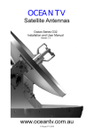
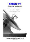
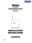
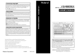
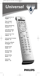
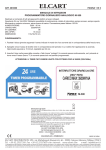
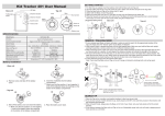
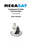
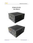
Ocean TV Ocean Series Antennas OCEAN TV Satellite Antennas Ocean Series O37M and O45M Installation and User Manual Version 1.34 www.oceantv.com.au OCEAN TV © Ocean1TV 2010 www.oceantv.com.au Ocean TV Ocean Series Antennas Antenna System Overview A complete satellite TV system, illustrated in Figure 1-1, includes the O45M antenna connected to a IDU, a satellite TV receiver, and a television set. Direct Broadcast Satellite Overview Direct Broadcast Service (DBS) satellites broadcast audio, video and data information from satellites located 22,000 miles in space. A receiving station, such as the O45M antenna, should include a dish and satellite receiver to receive the signals and process them for use by the consumer audio and video equipment. The system requires a clear view of the satellite to maximize the signal reception. Objects such as tall lighthouse, bridges and big ship that block this view will cause a loss of signal. The signal will be quickly restored once the antenna has a clear line of sight again. Heavy rain, cloud, snow or ice may also interfere with the signal reception quality. If the satellite signal is lost due to blockage or severe weather condition, services from the receiver will be lost (picture will freeze frame and may disappear). When the satellite signal strength is again high enough, then the receiver will resume providing desired programming services. Blocked ! Figure 1-2 Satellite Blockage OCEAN TV 2 www.oceantv.com.au Ocean TV Ocean Series Antennas System Components Antenna Unit The antenna unit houses the antenna positioning mechanism, LNB (low noise block), and control elements within a n enclosed weatherproof dome. Weather tight connectors join the power, signal, and control cabling from the below decks units. IDU (InDoor Unit) The IDU is the system’s user interface, providing access to the system and its functions through an LCD and three buttons. The IDU also serves as the vessel’s junction box, allowing the system to use vessel power, and supply and receive data to/from the antenna unit. Satellite Receiver The Satellite Receiver is a Set Top Box that allows the Satellite Signals to be displayed on the Television. Satellite Receivers are supplied by the end user or under contract by a Subscription Satellite TV Provider. Figure 1 – 3 System Components OCEAN TV 3 www.oceantv.com.au Ocean TV Ocean Series Antennas Ocean O37M Antenna Type Parabola Frequency Band Ku Band Operating Frequency 10.7GHz to 12.75GHz Dish Dimension 370mm Radome Dimension 440x430mm Antenna Weight 9kg Antenna Gain 31dBi M inimum EIRP 50dBW Polarization V/H or RHCP/LHCP Type of Stabilization 2-Axis Step M otor Elevation Range 5° to 90° Azimuth Range 400° Tracking Rate 50°/sec Temperate Range -20° to 70° Power 12~24VDC (19w at 12vdc) Ocean O45M OCEAN TV Antenna Type Parabola Frequency Band Ku Band Operating Frequency 10.7GHz to 12.75GHz Dish Dimension 450mm Radome Dimension 550x580mm Antenna Weight 15kg Antenna Gain 33dBi M inimum EIRP 49-48dBW Polarization V/H or RHCP/LHCP Type of Stabilization 2-Axis Step M otor Elevation Range 5° to 90° Azimuth Range 400° Tracking Rate 50°/sec Temperate Range -20° to 70° Power 12~24VDC (24w at 12vdc) Auto Skew Range -90° to 90° 4 www.oceantv.com.au Ocean TV Ocean Series Antennas Antenna System Overview Ocean TV System Overview Setup 1 1 Television with SD Satellite Receiver Antenna Coaxial Control Cable SD Satellite Receiver 12-24v DC Televisions IDU Indoor Unit NOTE:. Further Installation Options are available in Appendix E Figure 1 –1 System Diagram OCEAN TV 5 www.oceantv.com.au Ocean TV Ocean Series Antennas Contents 1 Introduction Specification………………….………………………………………………………………. 4 Antenna System Overview……………………………………………………………….. 5 Direct Broadcast Satellite Overview………………………….………………………. 6 Sy stem Com ponents……………………………………………………………………..… 7 2 Installation Unpacking the Unit………………………………..……………………...................... 9 Preparing for the installation…………………………………………………………. 10 Selecting the location………….………………………………………………….……… 11 Equipment and cable installation…………..…………………………………….…. 12 Setting the LNB Skew Angle (Manual Skew version only)…………………. 13 3 Operation Receiving Satellite TV Signals…………….………………………………………….. 15 Turning the System On/Off…………..………………..……………………………... 16 Changing Channels………………………….…………………...…..……………….…. 17 Watching TV…………………………………………………………..…………….…..…. 17 Switching between Satellites……………………………………………….…………. 17 Operating the IDU……………………………………….……………………………….. 18 Choosing the Correct Satellite to Track……………………...……………….... 19 4 Troubleshooting Sim ple Check……………………………………………..………………….……………. 21 Causes and Rem edies……………………………….……..……………………...……. 22 i Appendix A How to set the skew angle………………………………………………….....……. 23 ii Appendix B Satellite Cov erage Map…………………..…………………………..………..……. 26 iii Appendix C Firmware Upgrade…………………….……………………………………..…………. 27 iv Appendix D O37M Antenna Drawing..…………………….…..………...…………………..…. 31 O45M Antenna Drawing..…………………….…..……………………………....…. 32 v Appendix E Sy stem Diagram s..…………………….…..………...……………………..……..…. 33 vi Appendix F Satellite Coverage Maps……………….…..………...…………………….……..…. 40 5 Accessories Installation and User Accessories…………………………………………………. 42 OCEAN TV 6 www.oceantv.com.au Ocean TV Ocean Series Antennas Welcome Congratulations on purchasing the Ocean TV M arine Satellite Antenna System. The Ocean Series O37M and O45M satellite antenna system is a innovative and technologically advanced satellite In-M otion system. The O37M /O45M has a unique combination of state-of-the art components with the most sophisticated satellite acquisition and tracking programs to provide the following features: ■ Fast satellite acquisition ■ Gyro and Signal Stabilised smooth tracking ■ Compatible with any Satellite Receiver ■ Compatible with all Direct Broadcast Satellites (DBS) ■ Built-in Digital Broadcast Receiver (DVB) ■ Capable of High Definition receiving ■M ulti Output as standard (Foxtel IQ and Austar MyStar Compatible) Ocean TV Antennas have been designed to be simple to operate and provide years of trouble free performance. Welcome to the Ocean TV family. OCEAN TV Notes, Cautions, and Warnings Caution - Im proper handling by unqualified personnel can cause serious damage to this equipm ent. Unqualified personnel who tamper with this equipment may be held liable for any resultant damage to the equipment. Install under DRY condition ONLY. Do not install this system in the rain, or under wet conditions. Moisture may effect the electronics and v oid warranty. Warning - Two people are needed to install the antennas onto the roof. Do not try to install the antenna by y ourself. Note - Beforey ou begin, carefully read each of the procedures in this manual. If y ou have not perform ed similar operations on similar equipm ent, do not attempt to perform these procedures. OCEAN TV 7 www.oceantv.com.au Ocean TV Ocean Series Antennas Installation This section offers a general explanation of how properly to install the O37M and O45M antenna. Installation of the O37M or O45M antenna must be accomplished by or under the supervision of an authorized dealer for the Limited Warranty to be valid and in force. The steps in the installation and setup process are as follows: Unpacking the unit……………….……………………………………………….……………………. 9 Preparing for the installation…………………………………………….…………………………. 10 Selecting the location………….……………………………………….……………………………….. 11 Equipment and cable installation…………..……………………………………………………… 12 OCEAN TV 8 www.oceantv.com.au Ocean TV Ocean Series Antennas Unpacking the unit 1. Open box and remove packing material. The following items are included in the packaging of the O37M and O45M antenna. Item Description Quantity 1 O37M or O45M Antenna Unit 1 each 2 IDU (In Door Unit) 1 each 3 Power Cable 1 each 4 Coaxial Cable (10m) 1 each 5 Coaxial Cable (1m) 1 each 6 Installation & User M anual 1 set 7 Cable Right Hand Connectors (O37M Only) 1 Set of 6 Note: Optional approved Cables and accessories are available from Ocean TV. Table 2-1 Parts included 2. Lift dome out of box vertically. Do not turn box and “roll” out, or turn upside down to remove. Lift Unit st raight u p out of th e ca rt on ! Figure 2-1 Unpacking the unit OCEAN TV 9 www.oceantv.com.au Ocean TV Ocean Series Antennas Preparing for the installation Install Tools and Materials The O37/45M antenna system is designed for simple installation and setup. However, the following list of equipment or items should be available during installation of the O37/45M antenna. ■ Electric drill and drill bits ■ Socket wrench ■ Silicon sealant ■ Fastener suitable for specific application 1. Verification of the Vessel’s Power S upply. ■ Confirm that the vessel’s power supply is 12VDC~24VDC. 2. Verification of the S atellite Receiver and IDU’s attachment and the electricity supply ■ Attach Satellite Receiver and IDU in the interior of the vessel or the trunk. ■ Connect the power of Satellite Receiver and IDU. ■ Once the power of Satellite Receiver and IDU is verified, it confirms that both Satellite Receiver and IDU are working normally. 3. Procedure of the satellite’s attachment and installation. ■ Attach the satellite on the flat surface area of the vessel’s roof. ■ Connect each end of the Coaxial antenna cable to the satellite’s terminal and the IDU. ■ Connect the IDU and the Satellite Receiver box together through the coaxial cable. ■M ake sure that the satellite is working normally, once the power is supplied. Warning : Things to consider when installing the antenna. ■ Turn off the power when attaching or detaching the antenna. ■M ake sure that the attached satellite is fixed on the flat surface. ■ When attaching, ensure that all the products are adhered properly. ■ Ensure that all the cables are connected properly. OCEAN TV 10 www.oceantv.com.au Ocean TV Ocean Series Antennas Selecting the location Determine the optimum mounting location for the antenna radome assembly. It should be installed where : 1. The antenna has a clear line-of-sight view to as much of the sky as is practical. Choose a location where masts or other structures do not block the satellite signal from the dish as the vessel turns. 2. The antenna is at least 5 feet away from other transmitting antennas (HF, VHF and radar) that may generate signals that may interfere with the O37/45M antenna. The further away the O37/45M antenna is from these other antennas, the less impact their operation will have on it.0 3. Direct radiation into the antenna from vessels radar, especially high power surveillance radar arrays, is minimized. The radome should be as far away from the vessels Radar as possible and should NOT be mounted on the same plane as the vessels Radar. 4. The antenna radome assembly should be rigidly mounted to the vessel. If necessary, reinforce the mounting area to assure that it does not flex due to the vessel motion or vibration. If these conditions cannot be entirely satisfied, the site selection will inevitably be a “best” compromise between the various considerations. Perform a through site inspection on the roof for the antenna to be mounted. 1. The antenna must have a clear view of the sky and the horizon at all the directions to avoid blockage of the satellite signal. 2. The antenna should be on the top of the vessel. Best Location Poor Location Good Location Figure 2-2 Selecting the location OCEAN TV 11 www.oceantv.com.au Ocean TV Ocean Series Antennas Equipment and cable installation This offers a general explanation of how to install the IDU and satellite receiver properly to the inside of vessel connecting with coaxial cable. 1. The Coaxial cable is routed from the antenna to the IDU inside the vessel. 2. After Once deciding where to place the IDU and satellite receiver, make sure that both units are placed in a dry and protected area. 3. The IDU and satellite receiver should be placed away from any heat source and in an area with proper ventilation. 4. Ensure that there are at least 3cm of space around both units for ventilation and connection of cables. Do not stack the units on top of each other. 5. The following describes the basic wiring configurations for the O45M antenna system. ■ Connect the Coaxial cable to the O37/45M antenna port on the back of the IDU ■ Connect one end of the supplied coaxial cable to the receiver port on the back of the IDU ■ Connect the other end of the coaxial cable to the satellite receiver OCEAN TV 12 www.oceantv.com.au Ocean TV Ocean Series Antennas Setting the LNB skew angle (O37M Antenna Only) Figure 2-3 Satellite signals Signals transmitted in vertical (red) and horizontal (blue) wave offset exactly 90º from each other. Since linear satellite signals are oriented in a precise cross pattern, the O45M antenna’s receiving element, called an LNB (low-noise block) must be oriented in the same way to optiize reception. This orientation adjustment is referred to as the LNB’s “skew angle.” Figure 2-4 illustrates how skew determines the amount of signal the LNB collects. The more signal, the better the reception. Bad skew Good skew Best skew : LNB “signal collector” Figure 2-4 Best Skew Angle The correct skew setting varies depending on your geographic location, since the orientation of your antenna to the satellite changes as you move. For complete details about adjusting the LNB’s skew angle, see “Appendix A – How to S et the S kew Angle” All Ocean O37M S kew Angles are preset for Australian East Coast or New Zealand OCEAN TV 13 www.oceantv.com.au Ocean TV Ocean Series Antennas Ope ration The O37M /O45M antenna system is easy to use. Under normal conditions, operation of the O37M /O45M antenna requires no intervention from the user. Antenna unit initialization and satellite acquisition is completely automatic. Receiving Satellite TV Signal….……………………………………………………………….. 15 Turning the System On/Off…………………………………………………………….………. 16 Changing Channels…………….……………………………………….………………………….... 17 Watching TV…………………………….…………..……………………………………………….… 17 Switching between Satellites…………………..…………………………………………………. 17 Operating the IDU…..…………………………..…………………………………………………… 18 OCEAN TV 14 www.oceantv.com.au Ocean TV Ocean Series Antennas Receiving Satellite TV Signals Television satellites are located in fixed positions above the Earth’s equator and beam TV signals down to certain regions of the planet. To receive TV signals from a satellite, you must be located within that satellite’s unique coverage area. To check it, see “Appendix B – S atellite Coverage Map” In addition, since TV satellites are located above the equator, the O37/45M antenna must have a clear view of the sky to receive satellite TV signals. Anything that stands between the antenna and the satellite can block the signal, resulting in lost reception. Common causes of blockage include lighthouses, boat masts, trees, buildings, and bridges. Heavy rain, ice, or snow might also temporarily interrupt satellite signals. Turning the System On/Off Since power to the O37/45M system is controlled by the IDU, you can turn the antenna on or off by applying/removing operating power to the IDU. IMPORTANT It is important to following the following steps in the correct order. Failure to do so may lead to the satellites not being tracked correctly, or not tracking at all. Turning on the S ystem Follow the steps below to turn on your O37M /45M System. 1. M ake sure the antenna has a clear view of the sky. 2. Apply operating power to the IDU. 3. Wait one minute for system startup. The IDU will display the Tracking Satellite screen after system testing is complete. 4. Turn on the Satellite TV Receiver Set Top Box (Provided by your Pay TV Provider) Turning off the System Follow the steps below to turn off your O37/45M System. 1. Remove operating power from the IDU. 2. Turn off your satellite TV receiver and T V. Auto-Sleep Both the O37M and O45M have an auto sleep mode,. This mode is fully automatic and will usually happen at the dock after 10 minutes of no movement of the vessel. Occasionally, when the antenna comes out of auto sleep due to vessel movement, the satellite signal may be interrupted for a few seconds while the antennas starts tracking the correct satellite again. OCEAN TV 15 www.oceantv.com.au Ocean TV Ocean Series Antennas Changing Channels If you have followed the installation instructions, your system should be set to the satellite of your choice and the system should have downloaded the appropriate channel guides. When the O37M /O45M antenna system and satellite receiver is properly configured, it is easy to change he channel using the remote control that normally comes with the receiver unit. Watching TV The O37/45M antenna is designed to operate as efficiently and as reliably as possible when the vessel is moved and anchored. It is also the quickest satellite acquisition system available among the O37/45M antennas. If you have anchored the vessel and the antenna has completed to searching selected satellite, turn off IDU Power to avoid unnecessary use of power. Because the LNB receives its power from the Satellite Receiver through the IDU, the antenna will continue to receive the satellite TV signals. Switching between Satellites You can switch between satellites using the IDU by pressing Satellite select buttons. Follow the steps below to switch to another satellite. 1. Ensure that the LCD screen of the IDU is displayed. OPTUS C1/D3 ID: OPT AUTO _SLP S : 280 Figure 3-1 IDU LCD Screen 2. Press the Satellite select buttons to switch to another satellite. 3. The antenna shifts to track selected satellite. Wait for the Tracking Satellite screen to reappear with the ID of selected satellite displayed. Australia Systems are setup for Optus Satellites C1 and D3 as standard. Optus C1 and D3 are for use with Foxtel, Austar, Optus Aurora, VAST Intelsat 8 is for Select TV (No longer Available in Austalia) New Zealand Systems are setup for Optus D1 Optus D1 are for use with FreeView NZ and Sky NZ OCEAN TV 16 www.oceantv.com.au Ocean TV Ocean Series Antennas Ope rating the IDU Appearance POWER S/W LCD Display ON SATELLITE SELECT Ocean TV OFF Power Select Satellite Button SLEEP Sleep Button Figure 3-2 Appearance of IDU Functions of LCD Display ON Selected Satellite Satellite ID Operational Status Signal Strength Ocean TV OFF Power SATELLITE SELECT SLEEP Figure 3-3 Functions of LCD Display Explanation of words in LCD - INIT : It shows condition of initializing the antenna. - INIT-SCH : It shows condition of initial search mode. - SAT-M OVE: It shows condition of moving to another satellite. - S:xxx : It shows intensity of signal. - ID:xxx : It shows ID of acquired satellite. - GYRO-CAL : It shows condition of calibrating the Gyro Sensor. OCEAN TV 17 www.oceantv.com.au Ocean TV Ocean Series Antennas General Ope ration ON Turn on Power Switch OFF Information of IDU OCEAN TV LCD Shows information of IDU OPTUS C1/D3 START !!! Start Up Notice OPTUS C1/D3 INIT Antenna is being Initialized OPTUS C1/D3 GYRO-CAL Gyro sensor is being calibrated OPTUS C1/D3 SEARCH Antenna is searching for Satellite. The first time may take a little longer, but from then on will find faster as it remembers the elevation of the satellite. OPTUS C1/D3 ID: OPT TRACKING S: 288 Antenna is tracking Satellite. Satellite ID and Signal Strength is shown OPTUS C1/D3 ID: OPT AUTO-SLP S: 288 Antenna is in Auto-Sleep Mode. If no movement for 10 minutes Antenna enters Sleep mode for quite operation. 18 www.oceantv.com.au Ocean TV Ocean Series Antennas In case of Search Failure OPTUS C1/D3 INIT-SLP If Antenna cannot find signal, it will stop for 2 minutes and repeat searching for satellite OPTUS C1/D3 SEARCH Antenna is searching for select Satellite OPTUS C1/D3 ID: OPT TRACKING S: 288 Antenna is tracking Satellite. Satellite ID and Signal Strength is shown OPTUS C1/D3 ID: OPT AUTO-SLP S: 288 Antenna is in Auto-Sleep Mode. If no movement for 10 minutes Antenna enters Sleep mode for quite operation. Selecting Correct Satellite Use the Select Satellite buttons to chose the Satellite to receive. On start up, the system will default to the last selected Satellite. Australia Foxtel Austar Select TV OPTUS Aurora VAST OPTUS C1/D3 OPTUS C1/D3 Intelsat 8 OPTUS C1/D3 OPTUS C1/D3 New Zealand FreeView NZ Sky TV NZ OCEAN TV OPTUS D1-NZ OPTUS D1-NZ 19 www.oceantv.com.au Ocean TV Ocean Series Antennas Trouble Shooting There are a number of common issues that can affect the signal quality or the operation of the O45M antenna system. The following sections address these issues and potential solutions. Sim ple check………………….….…………………………………………………………………….. 21 Causes and Rem edies…..………………..……………………………………………………..…. 22 OCEAN TV 20 www.oceantv.com.au Ocean TV Ocean Series Antennas Simple check Can the antenna see the satellite? The antenna requires an unobstructed view of the sky to receive satellite TV signals. Common causes of blockage include trees, buildings, bridges, and mountains. Is there excessive dirt or moisture on the antenna dome? Dirt buildup or moisture on the dome can reduce satellite reception. Clean the exterior of the dome periodically. Is it raining heavily? Heavy rain or snow can weaken satellite TV signals. Reception should improve once the inclement weather subsides. Is everything turned on and connected properly? M ake sure your TV and receiver are both turned on and set up for the satellite input. Finally, check any connecting cables to ensure none have come loose. Is the antenna’s LNB set to the correct skew angle? (Manual Skew Ver. Only) To optimize reception, the antenna’s LNB needs to be set to the correct skew angle for the satellite you want to track. S ee “Appendix A – How to set the skew angle” for details. Only for Ocean O37M , O45M has Autoskew. OCEAN TV 21 www.oceantv.com.au Ocean TV Ocean Series Antennas Causes and Remedies Receiver Fault Your satellite TV receiver might be set up incorrectly or defective. First check the receiver’s configuration to ensure it is set up for the desired programming. In the case of a faulty receiver, refer to your selected receiver’s user manual for service and warranty information. S atellite Coverage Issue Television satellites are located in fixed positions above the Earth’s equator and beam TV signals down to certain regions of the planet (not worldwide). To receive TV signals from a satellite, you must be located within that satellite’s unique coverage area. See “Appendix-B S atellite Coverage Map” S atellite Signal Blocked The O37/45M Antenna needs a clear line of sight (LOS), view to the satellite for uninterrupted reception. Objects such as tall lighthouse, bridges and big ship that block this view will cause a loss of signal. The signal will be quickly restored once the antenna has a clear line of sight again. Heavy rain, cloud, snow or ice may also interfere with the signal reception quality. If the satellite signal is lost due to blockage or severe weather condition, services from the receiver will be lost (picture will freeze frame and may disappear). When the satellite signal strength is again high enough, then the receiver will resume providing desired programming services. S atellite Frequency Data Changed If some channels work, while one or more other channels do not, or if the antenna cannot find the selected satellite, the satellite’s frequency data might have changed. You can visit any Ocean TV-authorized dealer or Ocean TV distributor for assistance or visit www.oceantv.com.au Improper Wiring If the system has been improperly wired, the antenna will not operate correctly. Refer to the User M anual for complete system wiring information. Loose Cable Connectors We recommend periodically checking the antenna unit’s cable connections. A loose cable connector can reduce signal quality or prevent automatic satellite switching using the receiver’s remote control. Fasten the cable connector. OCEAN TV 22 www.oceantv.com.au Ocean TV Ocean Series Antennas How to Set up the Skew Angle Signals transmitted in vertical and horizontal wave offset exactly 90º from each other. Since linear sat ellite signals are oriented in a precise cross patt ern, the O45M antenna’s receiving element, called an LNB (low-noise block) must be orient ed in t he same way to optimize reception. This orientation adjustment is referred t o as the LNB’s “skew angle.” The correct skew setting varies depending on y our geographic location, since the orientation of y our antenna t o the satellite changes as y ou move. This appendix provides how t o set up the skew angle. Australian and New Zealand Versions of the O45M have Auto Skew. No adjustments are necessary. Adjustme nts are only necessary to the O37M. Ocean Series O37M in Australia are preset for Optus C1/D3 for use on Australian East Coast. Special Order O37M are available for Western Australia for use in Pe rth (No Extra Charge) Ocean Series O37M in New Zealand are preset for Optus D1. OCEAN TV 23 www.oceantv.com.au Ocean TV Ocean Series Antennas Setting the SkewAngle If you have determine the correct skew angle, follow the steps below to adjust the antenna’s LNB skew angle. Caution – To avoid bodily injury, be sure to turn off the antenna and disconnect power to all working components . SKEW ANGLE East Coast Australia OPTUS C1/D3 +30 Degrees Intelsat 8 +25 Degrees New Zealand OPTUS D1 - 60 Degrees West Coast Australia OPTUS C1/D3 0 Degrees All O37M in Australia are set for Optus C1/D3 and in New Zealand Optus D1. O45M have Autoskew, no adjusts are required. 1. Turn off the antenna and disconnect power to all wired components. 2. Using the screwdriver, remove the screws securing the radome. Then remove and set it aside in a safe place. 3. Locate the LNB assembly on the back of the antenna reflector. Reflector LNB Figure A-2T he Back of the Reflector OCEAN TV 24 www.oceantv.com.au Ocean TV Ocean Series Antennas 4. Loosen the four screws fastening the LNB. 5. Adjust the LNB clockwise or counter-clockwise, until the skew arrow on the LNB points to the skew angle that you determined earlier. LNB (-) direction (+) direction Figure A-3 LNB Skew Angle Adjustment Caution – Be sure to keep the LNB fully inserted into the hall to ensure the optimum performance. 6. Tighten the four screws. 7. Reinstall the radome. OCEAN TV 25 www.oceantv.com.au Ocean TV Ocean Series Antennas Satellite Coverage Map Television sat ellit es are locat ed in fixed positions above the Earth’s equat or and beam TV signals down t o certain regions of the planet (not worldwide). To receive TV signals from a sat ellit e, y ou must be locat ed within t hat sat ellit e’s unique coverage area. Satellite Coverage Map Satellite TV broadcast spot beams are aimed at land masses where the bulk of subscribers can be found. Thus, the signal strength decreases as you travel away from the land masses. The further you travel offshore you will require a larger size antenna. Although this information is believed to be correct, Ocean TV has no control over the variations on the actual satellite footprint coverage. Signal strength and reception can be affected by the weather conditions. Figure B-1 OPT US C1/ D3 Coverage Map NOTE: All of New Zealand - North and S outh Islands have complete Satellite Coverage OCEAN TV 26 www.oceantv.com.au Ocean TV Ocean Series Antennas Firmware Upgrade If sat ellite beam is changed or eliminat ed, y ou have t o upgrade firmware of IDU. Ocean TV dist ribut or provides the firmware. Firmware Upgrade If antenna cannot search the selected satellite or move incorrectly, you need to change the firmware of IDU. To upgrade the firmware, follow the steps below. 1. Prepare the SD memory card. Figure C-1 SD memory card 2. Before you use the SD memory card, you should format it to “FAT16(Default)” Please Note: Ocean TV is continually improving the Firmware installed on the IDU. If you wish to upgrade the firmware, please contact Ocean TV Australia. A small charge will be made for the supply of a compatible SD M emory Card. Only approved compatible memory cards are to be used, the use of a non approved memory card may result in the antenna not working correctly. OCEAN TV 27 www.oceantv.com.au Ocean TV Ocean Series Antennas Figure C-2 Formatting SD memory card 3. After formatting your SD card, copy the new software file from Ocean TV distributor. 4. Turn off the IDU. 5. Put your SD memory card into the SD slot of back side of the IDU. SD Memory Card Slot SD_CARD RS-232 RECEIVER ANTENNA 12VDC IN 12VDC OUT Figure C-3 The back of the IDU OCEAN TV 28 www.oceantv.com.au Ocean TV Ocean Series Antennas 6. Turn on the IDU. You can see the message “WRITING SOFTWARE” in LCD Display. WRITING SOFTWARE Figure C-4 Writing sof tware 7. If you see the message “FINISH TO WRITE”, IDU is finishing the software upgrade. You have to wait until the IDU is restarted. FINIS H TO WRITE Figure C-5 Finishing to write 8. Turn off the IDU. Take your SD memory card away from the IDU. 9. Turn on the IDU. OCEAN TV 29 www.oceantv.com.au Ocean TV Ocean Series Antennas Antenna Drawing OCEAN TV 30 www.oceantv.com.au Ocean TV Ocean Series Antennas Antenna Drawing O37M OCEAN TV 31 www.oceantv.com.au Ocean TV Ocean Series Antennas Antenna Drawing O45M Figure 1-1 O45M Drawing OCEAN TV 32 www.oceantv.com.au Ocean TV Ocean Series Antennas Appendix E System Installation Diagrams OCEAN TV 33 www.oceantv.com.au Ocean TV Ocean Series Antennas Ocean TV Installation Diagram Setup 1 1 Television with SD Satellite Receiver Antenna Coaxial Control Cable SD Satellite Receiver 12-24v DC Televisions IDU Indoor Unit This setup allows 1 SD Satellite TV Receiver to be installed. OCEAN TV 34 www.oceantv.com.au Ocean TV Ocean Series Antennas Ocean TV Installation Diagram Setup 2 3 Televisions with SD Satellite Receivers Antenna Coaxial Control Cable SD Satellite Receivers 12-24v DC Televisions IDU Indoor Unit This setup allows 1, 2 or 3 individual SD Satellite TV Receivers to be installed, providing separate control and programming to be viewed on each Television. OCEAN TV 35 www.oceantv.com.au Ocean TV Ocean Series Antennas Ocean TV Installation Diagram Setup 3 1 Television with HD Satellite Receiver Antenna Coaxial Control Cable HD Satellite Receiver 12-24v DC HD Television IDU Indoor Unit This setup allows 1 HD Satellite TV Receiver to be installed. OCEAN TV 36 www.oceantv.com.au Ocean TV Ocean Series Antennas Ocean TV Installation Diagram Setup 3a 1 Television with HD Satellite Receiver Antenna Coaxial Control Cable HD Satellite Receiver 12-24v DC HD Television IDU Indoor Unit This setup allows 1 HD Satellite TV Receiver to be installed. With one less Cable run from Antenna. OCEAN TV 37 www.oceantv.com.au Ocean TV Ocean Series Antennas Ocean TV Installation Diagram Setup 4 1 Television with HD Satellite Receiver 1 Television with SD Satellite Receiver Antenna Coaxial Control Cable HD Satellite Receiver SD Satellite Receiver 12-24v DC HD Television IDU Indoor Unit SD Television This setup allows 1 HD Satellite TV Receiver and 1 SD Satellite Receiver to be installed, providing separat e control and programming on 1 HD Television and 1 SDTelevision. OCEAN TV 38 www.oceantv.com.au Ocean TV Ocean Series Antennas Ocean TV Installation Diagram Setup 5 Multiple Televisions with HD Satellite Receivers Antenna Coaxial Control Cable HD Satellite Receivers Ocean TV HD Multi Switch 12-24v DC Available in 2/4/8/16 Outputs Televisions IDU Indoor Unit This setup allows multiple individual HD Satellite TV Receivers to be installed, providing separate control and programming to be viewed on each Television. The number of Televisions can be from 2 to 16 depending on the Multi Switch supplied. OCEAN TV 39 www.oceantv.com.au Ocean TV Ocean Series Antennas Appendix F Satellite Coverage Maps Satellite Coverage Map Satellite TV broadcast spot beams are aimed at land masses where the bulk of subscribers can be found. Thus, the signal strength decreases as you travel away from the land masses. The further you travel offshore you will require a larger size antenna. Although this information is believed to be correct, Ocean TV has no control over the variations on the actual satellite footprint coverage. Signal strength and reception can be affected by the weather conditions. Foxtel - Austar - Aurora Optus D3 Satellite Coverage Area O37M Requires 50dBW O45M Requires 48-49dBW Foxtel - Austar - Aurora - VAST Optus C1 Satellite Coverage Area O37M Requires 50dBW O45M Requires 48-49dBW OCEAN TV 40 www.oceantv.com.au Ocean TV Ocean Series Antennas Select TV Intelsat 8 Satellite Coverage Area O37M Requires 50dBW O45M Requires 48-49dBW SkyTV - FreeView NZ Optus D1 Satellite Coverage Area O37M Requires 50dBW O45M Requires 48-49dBW OCEAN TV 41 www.oceantv.com.au Ocean TV Ocean Series Antennas Ocean TV Accessories Ocean TV has a full range of accessories to make installation even easier. Below are just a few, browse www.oceantv.com.au for the latest accessories. A range of Ocean TV approved LCD Televisions is also available.. www.oceantv.com.au Compact Multiswitches Increase the number of HD TV Set top Boxes. OceanTV O37M, O45M, O60M, O600M and O850M Antennas are all HD/IQ Compatible, but when multiple HD/IQ Set Top Boxes are required a Compact Multiswitch can be used. These are available in 2, 4, 6, 8 and 12 users. All are compatible with IQ2 HD Units, and allow full IQ functions. Foxtel Austar Approvals: F10241 A03691 Cable Right Angle Adapters F-59 Plug to F-81 Socket Adaptor Right Angle. Often used when connecting the Coaxial Cable to the outputs of the Antenna. Neat, clean and secure connections, rather than bending the Coaxial Cable. Foxtel Dual Outlet Wall Plate Outlet Dual Wallplate 2 x F to F Foxtel designed to make your installation professional. Approvals Foxtel F24296 Build your Own Wall Plate Blank Wall Plates with 1, 2, 3, 4 or 6 available insert s. Insert what you need to build a custom wall plate for your entertainment system. Full Range of Inserts available Audio Video Scart Lead Audio Video Lead Scart Out-3RCA 1.5m Audio Video Lead Scart Out-3RCA 3.0m Approvals OCEAN TV 42 Foxtel F10273, F10430 www.oceantv.com.au Ocean TV Ocean Series Antennas High Quality RG6 Quad Shield Lead with Crimped Connectors This series is a high quality RG6 Quad shield cable designed specifically for use with the new generation of video signals like Pay TV installations, digital television and traditional analogue video signals. * RG6 coax cable with Quad shielding - just like what the pro installers use. * 75Ohm Impedance * Solid copper centre conductor with braid and foil shielding * High quality compression F58 plugs at each end Available in 4 lengths: 1.5M, 3M, 5M and 10M HDMI Audio Video Lead Audio Video Lead, HDMI To HDMI, 1.5, 3, 8m Foxtel F30507, F30508, F30533 Austar A091037 HDMI Lead with Extender - 15m or 20m Extending your high definition AV signals need not be an expensive exercise. Normally HDMI cables should be kept to a maximum of 5 metres to avoid any signal loss or degradation. Longer runs will require the use of external signal amplifiers. These affordable HDMI cables have built-in equaliser boosting the signal strength to enable cable lengths of 15m and 20m without the use of external power supply. Cables are ATC certified and is fully V1.3 compliant and supports 120Hz refresh rate. Right Angle HDMI Adaptors Adapts HDMI plug to socke t at right angles. Pe rfe ct for wall mounte d TV applications. Gold plated conne ctions. Two types available : R ight Angle Down HDMI Adaptor R ight Angle Up HDMI Adaptor HDMI Splitter 1 Input to 2 Outputs This tiny switcher routes high definition video (in multiple resolutions up to 1080p) and digital audio from any one of the two sources to display unit. Two inputs accommodate the simultaneous connection of upto two high definition video sources, such as satellite systems and HD DVD players. Switching is done automatically when signal is present on the ports or manually via the push button switch on the unit. OCEAN TV 43 www.oceantv.com.au Ocean TV Ocean Series Antennas Hard Wired IR Remote Extension Kit Hard Wired Infra-Red repeater kit for use in DIY &/or custom installations, to control an A/V device at a remote location (up to 1.8m). All connections are plug & play, and the kit includes discrete Flat IR target, junction box, double emitter & switch mode power supply. Will work with Foxtel including IQ2 STARTER PACK All you need for a simple install a basic in cabinet solution. RPT1041 Connection box with Three IR Transmitter Diodes An Infra-red receiver block and a 240Vac to 12Vdc P -Pack Foxtel IQ compatible IR T RANSMITTERS IR DIODES Single or paired Mini IR Transmitter diodes for placing near the equipment you wish to control with IR. 2 meter flexible black cable 3.5mm plugs to suit RPT1041 IR RECEIVER FLUSH BULLE T EYE 45x12mm Mounts flush into a ½" hole Connects to the RPT1041 module Three wire cable 3 meters long REPLACEMENT EYE 50x10mm² 2M wire to IR Receiver Black IR RECEIVER WALL PLATE Optional IR Receiver module Standard wall plate mounting with IR window & reception indicator Three wire screw terminal for Cable run up to 300 meters away Connects to the RPT1041 module White 115x70x15mm IR RECEIVER + VOLUME WALL PLATE 8W ATTENUATO R 115x70x70mm wall plate mounting with IR window & reception indicator. Requires RPT1041, cable, etc. With 12 position attenuator knob Adjusts Stereo 8W speaker lines Includes impedance matching for running multiple speakers too. OCEAN TV 44 www.oceantv.com.au Ocean TV Ocean Series Antennas Pre-programmed Pay TV Set-Top-Box Remote Control Designed s pecifi cally to ope rate your Pay T V Digi tal Se t Top Box and give you di rect ac cess to the spec ial features availa ble on the name b rand remo te. Approx 1 80mm lon g. Featur es: • Opera tes the FOXTE L® D igital Set Top Box Stock p roduc t may vary from pic ture HDMI Am plifier Splitter 1 Input to 2 Outputs Play your Ocean TV HD Satellite Receiver to more than one HDTV. Use this HDMI amplifier splitter to convert a single HDMI input signal into two identical and simultaneous output signals, all without losing high definition video and audio quality. Single Cable for both HD Video and Audio. • Supports HDMI 1.3b • Up to 2.25Gbps/225MHz HDMI 4 x 2 Switch Matrix Splitter Multiple HD Devices sw itched to Two HD Televisions Share four HDMI sources between two high definition TVs (HDTV). Essentially, you are able to use all of your high definition sources like Satellite Receiver, Blu-ray, PS3, HD set top boxes in your Boats Salon Entertainment centre to another HD display in a separate Cabin or Stateroom. Thus saving you thousands from purchasing HD players all over again! It also reduces cable clutter as well as the hassles of disconnecting and reconnecting sources to a TV with only one or two HDMI inputs. Switch easily between any four HDMI sources with the IR remote included, with up to 16 combinations. Mains plugpack included. • Supports HDMI 1.3b • Supports HDTV 1080p • Video amplifier bandwidth 2.25Gbps/225MHz 180 Watt 12VDC to 230VAC Pure Sine Wave Inverter Having a pure sine wave output makes this inverter ideal for running sensitive items like AC powered Pay Satellite TV Receivers, Notebook Computers and motor-powered devices like fans. The unit continually monitors operational parameters and will alert you to high or low battery voltage, output overload and over-temperature. A USB socket is also fitted and supplies 5VDC for charging USB devices like MP3 players or digital cameras. OCEAN TV 45 www.oceantv.com.au Ocean TV Ocean Series Antennas Ocean TV Satellite Television Antennas © Ocean TV 2010 Australia & New Zealand Dunham House, 2 Massey Street, Gladesville, 2111, Sydney, Australia. Phone: Sydney 0428 250 520 Auckland: 09 889 0882 www.oceantv.com.au [email protected] OCEAN TV 46 www.oceantv.com.au Ocean TV Ocean Series Antennas Examples of Installation Please send photos of your installation to [email protected] OCEAN TV 47 www.oceantv.com.au