Transcript
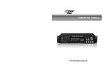
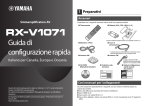
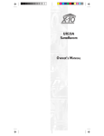
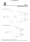
Touch Function
- - - - - - - - - - Power s witch button(standby) switch
On or off for waiting or On condition.
US B- - - - - - - - - US B Disk
USB
B AS S
TR E
SLEEP
S D- - - - - - - - - - S D Input
T UNE R
SAVE
AUTO
CH-
U S B /S D
FM
AUX
AUX- - - - - - - - - AUX I nput
AUTO- - - - - - - - Keep pressing for FM channel
CH+
S AVE- - - - - - - - S ave FM Channel
TUNE-
IR
1pc
2pcs
1pc
1pc
1pc
1pc
1pc
a
FM- - - - - - - - - - FM I nput
TUNE+
Inside Package:
Subwoofer Speaker
S atellite Speaker
Audio Cable
User Manual
R emote Control
FM ANT
Guarantee Card
AUX
FM
SD
SLEEP-
S
U
B
TRE+
+
SW
- - - - - - - - - - Previous s ong when US B/S D Input;
CHPrevious channel when FM I nput
+
TRE-
VOL
- - - - - - - - - Next song when US B/S D Input;
CH +
Next channel when FM I nput
1
2
S LEEP- /+ - - - - to Time on/off the speaker
3
4
5
7
8
9
REPEAT
0
RESET
S W- /+ - - - - - - S W volume to upgrade & attenuation of the key
6
TR E- /+- - - - - - TR EBLE volume to up grade & attenuation of the key
VOL- /+ - - - - - - Master Volume
Caution:
- - - - - - - - - - Press any key to choose the song
R EPEAT - - - - - R epeat
1.Do not splash or drip liquid on the surface
2.Do not place any objects f illed with water over the apparatus.
3.Do not block the ventilation holes.
4.For indoor use only.
5.When using high output signal don' t turn the volume to maxi
- mum to avoid distortion.
R ES ET - - - - - - When the volume is at the maximum, press
“RES ET” button.at the status while power on.
* If the Remote control can not function, it is because the battery of
Remote Control has been used up. Thank you.
NO.1
Front panel
TV
b
TUNE- /+- - - - - Previous/Next Channel Keep Pressing to search
the channel
- - - - - - - - - - Play & pause
SLEEP+
a
Satellites
*P.M.P.O: 4500W
*Channel: 2.1
*Output Power:30W+10Wx2
* Frequency R esponse:40Hz~20KHz
* S /N R ation:≥70dB
* Separation:≥45dB
* Speaker Unit: 6.5”+3”x2
Positioning the speakers
How to use the remote control
Satellites
Sp ecification:
Front panel
NO.4
S ystem connection diagram
a
Speakers
NO.5
NO.8
S ystem connection diagram
Positioning the speakers
FM RADIO ANTENNA
U S B /S D
FM
SLEEP
T UNE R
AUX
IR
Place the sub- woofer any place on the floor.(There is no
- directional requirement for the Bass effect.)
V CD
DV D
P O W E R S W IT C H
ON
~ ACI N
R A D IO A N T
R A D IO A N T
FM
A NT
FM
A NT
L
R
OUTP UT L
R
IN P U T
P O W E R S W IT C H
ON
OFF
~ ACI N
DV D
L
R
OUTP UT L
R
IN P U T
COMPUTER
Connecting equipment
Connect front speakers, a c enter s peaker, s urround speakers to
2.1 s peaker output terminals.
J acks and plugs of the connection cord are colored as
follows:R ed jacks and plugs:For the left channel of audio si
- gnals
NOTE:
NO.2
NO.3
Important
OFF
S PEAKER T ER MINALS
When using SD card function ,it is required to
choose SD card whose memory is more than
512M and also is legal edition.
Sub- woofer
TV
A U D IO
B AS S
b
AUDIO INPUT
A U D IO
TR E
TR E- - - - - - - - - - - Treble function key indicator lamp.
BAS S - - - - - - - - - - BAS S f unction key indicator lamp.
S LEEP- - - - - - - - - Sleep function key indicator lamp.
TUNER - - - - - - - - - Tuner function key indicator lamp.
US B/S D- - - - - - - - US B/S D function key indicator lamp.
FM- - - - - - - - - - - - FM function key indicator lamp.
AUX- - - - - - - - - - - AUX function key indicator lamp.
IR - - - - - - - - - - - - - The remote sensor.
- - - - - - - - - - - ST.BY function key.
INPUT- - - - - - - - - - Input function key .
MENU- - - - - - - - - - Menu function key.
VOLUME- - - - - - - when rotating the button, the function is
Volume+/ Volume - - - - - - - - - - - - Play/pause
- - - - - - - - - - - - Previous
- - - - - - - - - - - - Next
S D/MMC CAR D- - - S D card socket
U DIS K - - - - - - - - - US B socket
WARN IN G
Mobile phone, Mobile HardDisk Drive, MP4.
Electrons with USB Power are Not allowed!
Insert the plugs f ully into the jacks.Loose connections may
produce a humming sound or other noise interference.
NOTE :
* D o not leave magnetic objects near the speakers.
NO.6
Important:
Connect the speakers and all other external equipment and
finally connect the AC power cord.
NO.7
NO.9