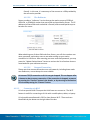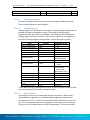
1
X-Link Data Logger Operations & Maintenance Manual Includes GPRSLink, IRIDIUMLink, HSPALink and CDMALink Part No. 8800-1190 Rev 1.63 August 19, 2015 Sutron Corporation X-Link Operations & Maintenance Manual, Rev 1.63 8/19/2015 pg. 2 TABLE OF CONTENTS Includes GPRSLink, IRIDIUMLink, HSPALink and CDMALink ............................................ 1 1. Introduction ............................................................................................................... 5 1.1. Models .................................................................................................................. 6 1.2. Applications ......................................................................................................... 6 1.3. Connections .......................................................................................................... 7 1.4. Earth Ground Point............................................................................................... 8 1.5. Input Protection .................................................................................................... 8 1.6. Terminal Strips ..................................................................................................... 8 1.7. Power Connections ............................................................................................. 10 1.8. Wakeup Button ................................................................................................... 14 2. Getting Started ........................................................................................................ 15 3. Measurements ......................................................................................................... 18 3.1. Sensors ............................................................................................................... 18 3.2. Inputs Available ................................................................................................. 18 4. LinkComm ............................................................................................................... 20 4.1. Stations List View – Getting Connected ............................................................ 20 4.2. Station View – Connected or Working Offline .................................................. 26 4.3. Dashboard Tab ................................................................................................... 32 4.4. Measurements Tab ............................................................................................. 34 4.5. Data Tab ............................................................................................................. 37 4.6. Telemetry Tab .................................................................................................... 38 4.7. Other Setup ......................................................................................................... 40 4.8. Diagnostics Tab .................................................................................................. 41 4.9. LinkComm for Phones and Tablets .................................................................... 46 5. Telemetry ................................................................................................................. 48 5.2. Retransmissions.................................................................................................. 50 5.3. Cell Phone Telemetry ......................................................................................... 51 5.4. Iridium Telemetry .............................................................................................. 56 5.5. Sending Messages to X-Link ............................................................................. 57 5.6. Telemetry Status ................................................................................................. 59 5.7. Message Check ................................................................................................... 61 5.8. Optimizing Data Usage ...................................................................................... 62 5.9. Transmissions and Measurements Coinciding ................................................... 63 6. Alarms ...................................................................................................................... 64 7. Setup ......................................................................................................................... 68 7.1. Measurement Setup ............................................................................................ 68 7.2. Telemetry Setup ................................................................................................. 92 7.3. Other Setup ......................................................................................................... 98 8. Measurement Setup Examples............................................................................. 100 8.1. RM Young Wind Speed and Direction ............................................................ 100 8.2. Thermistor ........................................................................................................ 101 8.3. Pressure Transducer (Analog Bridge Sensor) .................................................. 102 8.4. Thermocouple Sensor ....................................................................................... 104 8.5. Tipping Bucket ................................................................................................. 105 Sutron Corporation X-Link Operations & Maintenance Manual, Rev 1.63 8/19/2015 pg. 3 8.6. Solar Radiation Sensor ..................................................................................... 106 8.7. SDI-12 Multi-Parameter Sensor ....................................................................... 107 8.8. ISCO Sampler triggering based on Stage ......................................................... 108 8.9. Seametrics Flow Meter..................................................................................... 109 8.10. Computing Rate of Change .............................................................................. 112 9. Logging................................................................................................................... 114 9.2. Log Events........................................................................................................ 115 10. Password ................................................................................................................ 119 10.1. Creating a Password ......................................................................................... 119 11. Output .................................................................................................................... 120 11.1. Output Hardware .............................................................................................. 121 12. Time Keeping ........................................................................................................ 123 12.1. Iridium .............................................................................................................. 123 12.2. SDI Clock Synchronization .............................................................................. 124 13. Errors ..................................................................................................................... 125 13.1. Clearing Errors ................................................................................................. 125 13.2. Measurement Errors ......................................................................................... 125 13.3. System Errors ................................................................................................... 126 14. Command Line Interface ..................................................................................... 128 14.1. Why Use Command Line? ............................................................................... 128 14.2. About the Command Line Interface ................................................................. 128 14.3. Sending Messages ............................................................................................ 129 14.4. Status ................................................................................................................ 130 14.5. Setup ................................................................................................................. 130 14.6. Measurements................................................................................................... 132 14.7. Recording ......................................................................................................... 133 14.8. Downloading the Log ....................................................................................... 133 14.9. Examples .......................................................................................................... 134 14.10. Machine-to-Machine Communication ............................................................. 135 14.11. Auto Output ...................................................................................................... 135 14.12. Command Reference ........................................................................................ 135 14.13. Upgrading Firmware ........................................................................................ 139 15. Collecting Data ...................................................................................................... 141 15.1. Understand Your Selected Communications Method ...................................... 141 15.2. Decide where You Want the Data to Be Transmitted ...................................... 144 15.3. Estimate Communications Costs ...................................................................... 145 15.4. Sign the Agreement .......................................................................................... 148 15.5. Place the Order ................................................................................................. 149 15.6. Ordering Information ....................................................................................... 149 16. Data Formats ......................................................................................................... 153 16.1. TCP/IP Session................................................................................................. 153 16.2. Iridium Telemetry Header ................................................................................ 154 16.3. Pseudobinary B Data Format ........................................................................... 156 16.4. Pseudobinary C Data Format ........................................................................... 157 16.5. Pseudobinary D Data Format ........................................................................... 159 16.6. Six Bit Binary Encoded Format ....................................................................... 161 Sutron Corporation X-Link Operations & Maintenance Manual, Rev 1.63 8/19/2015 pg. 4 16.7. Pseudobinary over SMS ................................................................................... 163 16.8. SHEF and SHEFFIX Data Format ................................................................... 163 16.9. Sutron Standard CSV ....................................................................................... 165 17. More about SDI-12 ............................................................................................... 166 17.1. Overview .......................................................................................................... 166 17.2. Wiring Guidelines ............................................................................................ 167 17.3. Connector ......................................................................................................... 167 17.4. Setup of SDI sensors ........................................................................................ 167 17.5. Useful SDI commands ..................................................................................... 168 18. Modbus................................................................................................................... 169 18.1. Modbus Hardware Interface ............................................................................. 169 18.2. Modbus Setup................................................................................................... 170 18.3. Modbus Function Codes................................................................................... 172 18.4. Sutron Function Codes ..................................................................................... 174 19. Appendix A – Specifications ................................................................................ 181 20. Appendix B – Sutron Customer Service Policy .................................................. 184 21. Appendix C – Commercial Warranty ................................................................. 185 21.1. Sutron Manufactured Equipment ..................................................................... 185 21.2. Non-Sutron Manufactured Equipment ............................................................. 185 21.3. Repair and Return Policy ................................................................................. 186 22. Appendix D – Installation .................................................................................... 187 22.1. Physical Mounting............................................................................................ 187 22.2. Power Budget Calculations .............................................................................. 188 22.3. Cabling Precautions.......................................................................................... 189 22.4. Antenna Mounting Details ............................................................................... 190 23. Index ....................................................................................................................... 191 Sutron Corporation X-Link Operations & Maintenance Manual, Rev 1.63 8/19/2015 pg. 5 1. Introduction The X-Link family of products provides simple telemetry anywhere. X-Link has two purposes: To collect and store data from meteorological and hydrological sensors. To send that data wirelessly to a central system, phone or other station. IRIDIUMLink, GPRSLink, HSPALink and CDMALink are members of the X-Link family of products. The only difference between the products is in the built-in communications package: X-Link basic unit that includes all the measurements and logging capability of X-Link family but with no modem installed. IRIDIUMLink includes a transmitter that can deliver data to you from anywhere in the world via the Iridium satellite constellation. GPRSLink includes a quad band GSM cell phone modem that can operate when the unit is within range of a cell phone network of companies like AT&T and T-Mobile. HSPALink includes a quad band GSM cell phone modem that can operate at 4G speeds on cell phone networks of companies like AT&T and T-Mobile. CDMALink includes a CMDA cell phone modem that uses networks of companies like Sprint and Verizon. Each X-Link has the same sensor connectors and is capable of making the same sensor measurements. Up to 16 independent measurements can be set up to collect data via SDI-12, analog, and digital interfaces. LinkComm software is used to easily set up and maintain X-Link either via a direct USB connection or remotely over cell, satellite, or Wi-Fi. LinkComm runs on Windows PC, OS X, iPhone/iPad, and Android platforms. X-Link was built to work with Sutron WIN. Sutron WIN makes it easy to collect data from multiple stations over different communication networks. Sutron WIN makes it possible to view all your data using a web browser. Sutron Corporation 1.1. X-Link Operations & Maintenance Manual, Rev 1.63 8/19/2015 pg. 6 Models X-Link comes in several versions to meet varied customer needs. The table below shows the models currently offered. Check with Sutron for additional models or for a customized version of X-Link. Model X-Link-1 X-Link-1E IRIDIUMLink-1 IRIDIUMLink-1C IRIDIUMLink-1E IRIDIUMLink-1L GPRSLink-1 GPRSLink-1C GPRSLink-1E GPRSLink-1L HSPALink-1 HSPALink-1C HSPALink-1E HSPALink-1L CMDALink-1 CDMALink-1C CDMALink-1E CDMALink-1L 1.2. Description Basic unit with no modem, provides measurement and data logging capability Basic unit in NEMA-4 box with no modem Basic IRIDIUMLink unit IRIDIUMLink-1 in a NEMA-4 box with battery and internal antenna IRIDIUMLink-1 in a NEMA-4 box with connector for external antenna IRIDIUMLink-1 in a NEMA-4 box with connector for external antenna with a antenna lightning arrestor Basic GPRSLink for operation on GSM networks such as T-Mobile, AT&T, most all International service providers. GPRSLink-1 in a NEMA-4 box with battery and internal antenna GPRSLink-1 in a NEMA-4 box with connector for external antenna GPRSLink-1 in a NEMA-4 box with connector for external antenna with a antenna lightning arrestor Basic HSPALink for operation on GSM networks such as T-Mobile, AT&T, most all International service providers. Allows for 4G speeds. HSPALink-1 in a NEMA-4 box with battery and internal antenna HSPALink-1 in a NEMA-4 box with connector for external antenna HSPALink-1 in a NEMA-4 box with connector for external antenna with a antenna lightning arrestor Basic CDMALink for operation on Verizon and Sprint networks CDMALink-1 in a NEMA-4 box with battery and internal antenna CDMALink-1 in a NEMA-4 box with connector for external antenna CDMALink-1 in a NEMA-4 box with connector for external antenna with a antenna lightning arrestor Applications X-Link products are designed to operate in a wide range of applications including: Surface water level, flow and quality Groundwater level and quality Offshore monitoring Mining / geotechnical Weather monitoring and warning Oceanic monitoring and warning Oil and gas production Any low-power, remote data acquisition system Sutron Corporation X-Link Operations & Maintenance Manual, Rev 1.63 1.3. Connections 1.3.1. USB Connector 8/19/2015 pg. 7 X-Link products come with a mini USB connector for connection to the USB port on a computer. X-Link uses the USB port for serial data communication only. Memory sticks are not supported. LinkComm software is used to talk to an X-Link over the USB cable. LinkComm can use USB on both Windows PCs and Mac OS X. LinkComm software ships with every X-Link. However, the latest version is always available from http://www.sutron.com/downloads.htm (search on “LinkComm”). Virtual COM Port drivers created by FTDI are included with LinkComm software. The drivers for Windows PCs are named “CDM v2.0.8.30 WHQL Certified.exe”. The drivers for OS X (v10.9+) are named “FTDIUSBSerialDriver_v2_3.dmg”. Please install the drivers before connecting X-Link to your PC. Some Windows PCs are able to install the drivers automatically but only if the PC is connected to the internet. If the PC is not connected to the internet, and XLink is connected to the PC before the drivers are installed, LinkComm may not be able to communicate with X-Link. In that case, please install the provided drivers and connect X-Link to a different USB port. For further help with the drivers, please visit the FTDI website. You will not be able to talk to X-Link without a successful installation of this driver. The USB connector is not compatible with USB memory sticks or the USB connection on a smart phone or PDA. Sutron Corporation 1.4. X-Link Operations & Maintenance Manual, Rev 1.63 8/19/2015 pg. 8 Earth Ground Point A connection point has been provided for an Earth ground point. This critical connection always should be made first and should never be overlooked. Any time a sensor cable is attached to the terminal strip, exposure to dangerous electrical surges is possible. There are many possible causes, but the most common source of a surge is created from nearby lightning strikes. Protection is afforded only when the earth ground is properly connected to a qualified ground source. Failure to properly connect the Earth ground point will lead to failures in the field due to surges. To install a proper ground connection point: 1. Use a copper ground rod driven into the ground at least 6 feet. 2. Attach a very heavy gauge (#4 Solid Copper) wire between the rod and the XLink Earth ground point. The connection point can accept up to a 4 gauge solid copper wire. If a heavier gauge copper wire is used to connect to the ground rod, a reducer may be necessary to connect to the terminal on X-Link. Firmly secure the screw on the ground point firmly on the copper wire. Do not rely on AC power ground connections as they are not always properly grounded and may introduce other surges. 1.5. Input Protection X-Link features gas tube protection on all sensor inputs. 1.6. Terminal Strips The two terminal strips built into X-Link provide the connections for battery, solar panel, sensors, and outputs. The table below describes the purpose of each connection. Additional information on using the connections follows. Sutron Corporation X-Link Operations & Maintenance Manual, Rev 1.63 Terminal Block Description 8/19/2015 pg. 9 Notes 1 GND Main Battery/Power - 2 + BATTERY (8-16V) Main Battery/Power + 3 GND Solar Panel - 4 + SOLAR (30W MAX) Solar Panel + 5 RS485 A SDI-12 over RS-485, Modbus slave 6 RS485 B SDI-12 over RS-485, Modbus slave 7 WS/DIG IN1 Wind Speed or Digital Input 1 8 TB/DIG IN 2 Tipping Bucket or Digital Input 2 9 GND 10 +SW POWER 11 DOUT 12 GND Ground for sensor Switched Power (turned on during warm-up and analog sensor measurement) Digital Output (open collector, turned on manually, with alarms, or via equations) Ground for SDI-12 13 SDI-12 PWR Power to SDI-12 sensors (500 ma max) 14 SDI-12 DATA SDI-12 Data Sutron Corporation X-Link Operations & Maintenance Manual, Rev 1.63 8/19/2015 pg. 10 Terminal Block 26 AGND Analog ground 25 Analog 0-5V ‘A’ Voltage input for sensors with 0-5V output 24 AGND Analog ground 23 Analog 0-5V ‘B’ Voltage input for sensors with 0-5V output 22 DIFF ‘C’ (- ) Differential voltage input for bridge type sensors 21 DIFF ‘C’ (+) Differential voltage input for bridge type sensors 20 AGND 19 VREF 18 DIFF ‘D’ (- ) Analog ground 2.5V output (turned on during warm-up and analog sensor measurement) Differential voltage input for bridge type sensors 17 DIFF ‘D’ (+) Differential voltage input for bridge type sensors 16 AGND Analog ground 15 4-20ma IN Earth GND Earth Ground Input for 4-20ma sensor Attach via a heavy gauge (4 to 10 AWG) wire to earth ground rod driven 6 feet into earth. 1.7. Description Notes Power Connections 1.7.1.1. Battery X-Link requires an external +12V power source to operate. The most common power source is a lead-acid or gel cell type battery. Sutron Corporation X-Link Operations & Maintenance Manual, Rev 1.63 8/19/2015 pg. 11 In the figure above, the battery and solar panel are shown connected Connect the battery to terminals #1 and #2 labeled - GND and + Battery (8-16V) on the external terminal strip. The acceptable voltage range for X-Link to operate correctly is 8 to 16 volts. The capacity of the battery shall be chosen to support the overall station power budget reflecting the type of sensors, how often they are measured, and desired length of operation without solar power input. Typical small stations reading a few sensors once per hour will find the 4 AHr battery sufficient. Power hungry sensors and aggressive measurement schedules will require larger batteries and or larger solar panels. If a SDI-12 sensor is used, a minimum of 10V may be required. The use of 4-20ma sensors may also necessitate using a battery of 12V minimum. Consult the sensor manual for requirements. 1.7.1.2. Solar Panel X-Link features a built-in solar power regulator capable of handling up to 30 watts. Connect the solar panel to terminals #3 Solar Panel - and #4 Solar Panel +. See figure above for connection details. The solar panel input with sufficient sun illuminating the panel will power the station in situations where the battery needs to be removed from the circuit momentarily for replacement. Long term operation without the battery connected is not recommended and transmissions via internal Iridium or Cellular modems may not be possible due to the regulator not being capable of supplying the necessary current during transmissions. Sutron Corporation X-Link Operations & Maintenance Manual, Rev 1.63 8/19/2015 pg. 12 o The battery will get charged via the solar power connector. o The solar input will handle voltages from 16 to 22 Volts DC. o You may connect a power source other than a solar panel (e.g. a power supply) as long as it conforms to the voltage specification above. Please note that a battery is still required for long term operation and to ensure enough current is available for reliable transmissions. Typical stations with few sensors measuring infrequently may find a 2W or 5W panel sufficient while stations with more frequent measurements will require a larger 10 Watt or larger panel. The internal solar panel charger is designed to output up to 1.5 Amps when peak charging conditions from a solar panel are present. The Maximum battery size recommended for this charger is a 4AHr gel cell battery. If the station requires larger battery sizes, Sutron recommends using an external solar charger regulator such as the Sutron model 5100-0411 or similar. Assistance in calculating power budgets may be found here: http://www.sutron.com/customerservice/Conversions_Calcuations/PowerBudget.htm 1.7.2. SDI-12 Connections SDI-12 sensors connect to terminals #12, #13 and #14 labeled as GND, SDI-12 PWR and SDI-12 Data. Because SDI-12 sensors are addressable, multiple SDI-12 sensors may connected to these terminals. (See page 78.) 1.7.3. Tipping Bucket Connection The tipping bucket connection is #8, labeled TB/DIN IN 2, and #9, labeled GND. This input is compatible with a dry contact switch common to most tipping buckets. In most circumstances it doesn’t matter which side of the switch is connected to TB/DIN IN and GND. (See page 105.) 1.7.4. Wind Speed Connection The wind speed connection is #7, labeled WS/DIG IN 1. This input is compatible with wind sensors with a 0-5 volt frequency output. Typically, the sensor will also be connected to #10, + SW Power and #9 GND. For measurement setup, see the wind speed section. (See page 100.) 1.7.5. Digital Inputs WS/DIG IN 1 and TB/DIG IN 2 are also general purpose digital inputs capable of making counter, frequency, period, or level measurements. The maximum frequency of any digital input is 10Khz. Sutron Corporation 1.7.6. X-Link Operations & Maintenance Manual, Rev 1.63 8/19/2015 pg. 13 Analog Connections The terminal has connections for five analog inputs. The inputs labeled Analog A and Analog B are for 0-5V sensors. The inputs labeled Analog C, and Analog D support +/-39mv, +/-312mV or +/2.5V sensors. There is a separate connection for 4-20ma sensors. Detailed notes describing how to connect sensors to the terminal blocks are provided in the Setup section of this manual, beginning on page 68. 1.7.7. RS-485 X-Link can use the RS-485 connection in two ways: SDI-12 and Modbus. 1.7.7.1. Modbus over RS-485 X-Link can function as a Modbus slave. In this mode, it can provide measurement results, log file access, and more. Please see page 169 for details. 1.7.7.2. SDI-12 over RS-485 Sutron products such as the CF Bubbler support this connection. SDI-12 over RS485 is generally used to allow longer cable lengths. RS-485 does NOT provide power to the sensor. Do not forget to provide appropriate power to the sensor! 1.7.8. Outputs The following output capability exists in the X-Link product. 1.7.8.1. Digital Output On Terminal #11 is the digital output (DOUT). It is an open collector switch. The switch can be turned on and off manually (by issuing a command via LinkComm or via a cellular, satellite, or Wi-Fi message), it can be turned on when the station goes into alarms. 1.7.8.2. Switched Power Terminal #10 is the switched battery output. It is labeled +SW POWER. This line will output a voltage during the warmup for the following measurement types: analog, SDI-12, and digital. It will also always turn on when an analog measurement is made. This line will output whatever voltage is powering X-Link on the battery terminal. 1.7.8.3. VREF Terminal #19 outputs a 2.5 V reference during the warmup for an analog sensor and when an analog measurement is made. Sutron Corporation 1.8. X-Link Operations & Maintenance Manual, Rev 1.63 8/19/2015 pg. 14 Wakeup Button X-Link models manufactured in 2013 or later have a wakeup button on the top right side of the box. Pushing the button will have X-Link turn on its Wi-Fi chip and modem. When visiting a field station, push the button, then use your mobile phone or tablet to connect to X-Link via Wi-Fi. When the button is pushed, the green LED will light up for a few seconds, indicating that Wi-Fi is now on. If the button is held down for 5 seconds, the red LED will come on too. Keep holding the button until the red LED turns off in order to reboot X-Link. Sutron Corporation X-Link Operations & Maintenance Manual, Rev 1.63 8/19/2015 pg. 15 2. Getting Started Follow these steps to become familiar with X-Link. 1. Connect power to pins 1 and 2 as shown on page 10. A 9V battery will work fine for short-term testing without transmitting. For longer operation or if testing with a SDI-12 sensor, connect a larger battery or power supply. Typical applications use a 4AH or 7AH battery with a 5 to 10 watt solar panel. 2. As soon as power is applied, the LED will flash, first rapidly and then every several seconds. This indicates the X-Link is operating. 3. Download the LinkComm program. Go to http://www.sutron.com/downloads.htm, search on “LinkComm”, and download the installation package for your operating system, e.g., “Windows”, “OSX”, or “Android” (for “iOS”, please use App Store on your mobile device) o For Windows, extract all files to a folder on your computer. You may run LinkComm directly from this folder by double-clicking “LinkComm.exe”, or, to install LinkComm so that it appears on the Start menu, double-click “setup.exe” (Administrator privileges are required to install LinkComm) o For OSX, mount the downloaded disk image, and copy the LinkComm application bundle to your “Applications” folder o The download package contains all required software including LinkComm, X-Link upgrade files, USB drivers, and the user manual 4. Connect the USB cable from your computer to X-Link. If the computer does not automatically install the FTDI USB-to-serial drivers for you, install them manually. a. On Windows, if you installed LinkComm, then simply select Install X-Link USB Drivers from the Windows start menu. Or, locate and run “CDM_v2.08.30 WHQL Certified.exe” in the installation package you downloaded in the previous step b. On OSX, locate and run the installer in “FTDIUSBSerialBus_v2_3.dmg” 5. Run LinkComm Sutron Corporation X-Link Operations & Maintenance Manual, Rev 1.63 8/19/2015 pg. 16 a. In the window that comes up, press “+” to create a new station. Set “Station type” to match your type of X-Link, set “Connect type” to “Serial”, and set “COM port” to the port assigned to X-Link b. Press the “Connect” button to connect to X-Link. LinkComm will connect to X-Link and download the setup and recent data (if those options are selected in the station setup, above) Sutron Corporation X-Link Operations & Maintenance Manual, Rev 1.63 8/19/2015 pg. 17 6. Select the Measurements tab. This is where you will set up X-Link to measure, process, and log data. If the unit is in its factory default condition, there will be no measurements enabled. To set up measurements, see page 68. We recommend that you setup and test all measurements before deploying the station in the field. 7. Select the Telemetry tab. This is where you will set up X-Link to transmit the data. If the unit is in its factory default condition, there will be no telemetry enabled. To set up telemetry, see page 92. We recommend that you setup and test the telemetry setup before deploying the station in the field. 8. Select the Diagnostics tab. This is where you set the unit to factory defaults or to use the terminal tool. To set up diagnostics, see page 41. 9. To access the main menu, press the button in the upper left. Use options on the main menu to send/get setups, start/stop recording, exit the application, etc. Sutron Corporation X-Link Operations & Maintenance Manual, Rev 1.63 8/19/2015 pg. 18 3. Measurements A measurement is the process of collecting data from a sensor. X-Link provides the ability to establish up to 16 measurements, each with its unique setup. Each measurement will occur periodically and provide one or more results, which are usually related to weather conditions. Measurement results may be logged. The log can hold almost 250,000 unique readings. Logged measurement results may be transmitted via cellular or satellite modems. 3.1. Sensors As a data logger, one of X-Link's primary functions is to measure and log data from sensors. All commonly used environmental sensors are supported. Here is a list of some of the sensors supported and available through Sutron: 3.2. AT/RH (Air temperature and relative humidity) - using analog or SDI-12 sensors Precipitation – using a tipping bucket Wind Speed / Wind Direction - RM Young or Gill ultrasonic via frequency, analog, and SDI-12 inputs (includes vector averaging) Stage - using SDI-12 shaft encoder, radar level recorder, stage discharge recorder, analog submersible, bubbler Barometric Pressure - using an SDI-12 Accubar or a built-in Accubar. Solar Radiation via differential analog input Inputs Available Each of these inputs can have one sensor connected to it, except for SDI-12, which can connect to several sensors. Analog inputs Two 0-5 V single ended analog inputs Two differential analog Inputs (for bridge type sensors) One 4-20mA input Digital inputs Two general purpose digital inputs that can be set up as o Counter digital input (e.g. tipping bucket) o Frequency/period input (e.g. wind speed) Sutron Corporation X-Link Operations & Maintenance Manual, Rev 1.63 8/19/2015 pg. 19 o Level digital inputs (read line state as 1 or 0) RS-485 o Support for certain sensors such as the Seametrics flow meter SDI-12 input o SDI-12 V1.3 compliant supports multiple sensors all connected to the same bus One Accubar connector (internal) Please see the Measurement Setup section, beginning on page 68, for details on how to set up a measurement. Sutron Corporation X-Link Operations & Maintenance Manual, Rev 1.63 8/19/2015 pg. 20 4. LinkComm LinkComm is a software application designed to talk to X-Link. LinkComm is free. LinkComm is used to: Check X-Link status Set up an X-Link station Download and graph the log from X-Link Upgrade X-Link firmware Calibrate connected sensors …and more... Download LinkComm from here: http://www.sutron.com/downloads.htm (search on “LinkComm”). The PC version is supported on Windows 7 and higher. Operation on Windows XP is possible so long as a graphics driver is installed that fully supports either OpenGL v2.1 or DirectX 9.0. The version for Mac supports OSX 10.x and above. Mobile versions of LinkComm are also available to run on Apple iPad and iPhone, and on Google Android phones and tablets. They can be found on the Apple® App Store™, and Google® Play Store™, respectively. Quick Start Guides that describe how to use the mobile versions of LinkComm are also available for download from the link above. To connect LinkComm to X-Link via USB, the FTDI USB to serial drivers must be installed. Please see section 2, “Getting Started”, for details on how to get these installed. 4.1. Stations List View – Getting Connected LinkComm requires you create a station definition before you can connect to it or work on its setup. You’ll normally create an entry in the Stations list for every station you manage on an on-going basis. It’s easy to add and delete station entries, so you’ll also often create a temporary station entry for ad-hoc connections. Sutron Corporation X-Link Operations & Maintenance Manual, Rev 1.63 8/19/2015 pg. 21 You use LinkComm’s “Stations List View” (sometimes called “Connect View”) to perform station management. This is the view you first see when LinkComm starts up. To add a new station, press the “+” button in the stations list header. To delete a station definition, select the station and then press the minus sign in the stations list header. LinkComm will prompt to make sure you really want to delete the station, since this action cannot be undone. Note: All settings (station and connect settings, notes, and site images) for every station you define are saved automatically as you make changes. Hence, there is no need to select any kind of “Save” menu item. 4.1.1. Station Settings The top portion of the Station List View is where you configure station settings like station type and name. This is also where you’ll find the Connect and Work Offline buttons. When setting up a new station, be sure to set “Station type” to the type of X-Link you’re setting up. Also be sure to set “Station name” to the name you desire for the station. This name is updated if it differs from the name stored in X-Link anytime you get the setup from the actual X-Link, though you will be prompted first regarding the difference, if any. Sutron Corporation X-Link Operations & Maintenance Manual, Rev 1.63 8/19/2015 pg. 22 You can change the picture used for your station definition by selecting the “Change…” text underneath the picture. The menu that pops-up also gives you the ability to restore the picture to its default for the station type. If a camera is available, you also have the option of taking the picture to be used. Press the “Connect” button to connect to X-Link. When connected, you are able to see current data values, historical data, and the setup in the unit. Press the “Work Offline” button if you want to make changes to the setup stored locally for the station, without connecting to X-Link. When you later connect to X-Link, LinkComm will notice the setup in the unit is different than the one stored locally, and will ask you which one to use (LinkComm first asks if you want to retrieve the setup from X-Link. If you answer “No”, LinkComm then asks you if you want to send the local setup to X-Link). 4.1.2. Connection Settings There are several ways to connect to X-Link: Directly via USB cable Remotely via TCP/IP Remotely through the Sutron Redirector Locally via X-Link’s Wi-Fi Basic features, such as checking status and changing setup are available via all connection types. However, some features, such as upgrading the firmware, are available only over USB. Additionally, changing some of the settings and disabling the password is not possible remotely. “Check setup on connect”, when checked, will cause LinkComm to retrieve the setup from X-Link every time you connect. You may choose to disable this feature to reduce data costs (e.g., for cellular connections that cost money). “Get recent data on connect”, when checked, will cause LinkComm to download the last week of data for display in a graph on the dashboard tab, every time you Sutron Corporation X-Link Operations & Maintenance Manual, Rev 1.63 8/19/2015 pg. 23 connect to X-Link. This can be a considerable amount of data (several k-bytes). Here again, you may choose to disable this feature to reduce data costs. 4.1.2.1. Connecting via USB LinkComm can connect directly to X-Link via a USB cable. Simply connect a USB cable from your computer to X-Link. USB drivers are included in the LinkComm download package. These drivers are required to connect to X-Link over USB. Please see Section 2, Getting Started, for more details on their installation. Please be sure to follow the instructions in Section 2, “Getting Started”, to download and run LinkComm, connect it to X-Link, and verify communications before setting out to the field. Indeed, we recommend that station setup be completed and tested at the office before deploying the station. To connect via USB, set “Connect type” to “Serial”, and then set “COM port” to the port assigned to X-Link by the operating system. When X-Link is first connected to a USB port, Windows will create a virtual Com port (e.g. COM5). Each time the cable is connected to a different USB connection, a new port is created. The port assignment can be confirmed using Windows Device Manager (Control Panel). If LinkComm does not list the assigned port, please enter it manually. 4.1.2.2. Connecting Remotely LinkComm can also talk to a GPRSLink, HSPALink, and CDMALink over the internet. To do so, GPRSLink, HSPALink, and CDMALink need to have the Listening setting enabled. Alternatively, to reduce power consumption, the system can be configured to check for messages periodically. A message can be sent to the station asking it to temporarily turn on listening. Please see the Message Check section on page 61 and Sending Messages to X-Link on page 57. 4.1.2.2.1. TCP/IP If the IP address of an HSPALink, GPRSLink, or CDMALink is known, it can be connected to directly. It is up to cell service provider to 1. Give a static IP address. This means that the IP address of X-Link does not change over time. Alternatively, you may send an SMS to the X-Link asking what its current IP address is. 2. Provide VPN access. It is not always possible to directly connect to X-Link over the internet because it is protected by the cell service provider’s Sutron Corporation X-Link Operations & Maintenance Manual, Rev 1.63 8/19/2015 pg. 24 firewall. In this case, it is necessary to first connect to a VPN provided by the cell service provider. 4.1.2.2.2. The Redirector Sutron provides a “redirector” service that can be used to access a GPRSLink, HSPALink, or CDMALink station that uses a SIM card provided by Sutron. The IP addresses of these SIM cards are behind a firewall, and so need special steps to be taken for access. When obtaining one of these SIM cards from Sutron, you will also receive a user name, password, and station name to use when setting up your station connection in LinkComm. After entering your user name and password, you may press the “Update Station Names” button to retrieve the list of stations that are associated with your redirector account. 4.1.2.2.3. Dropped Connections Please note that remote connections over cell networks, including those made over Redirector, are not always the most reliable. An internet TPC/IP connection to X-Link can get dropped. This can happen after a timeout or due to a poor connection. If the connection is dropped, reconnect by pressing the “Connect” button in the header, or by returning to the Stations List view and pressing the “Connect” button 4.1.2.3. Connecting via Wi-Fi X-Link can provide a Wi-Fi hotspot that LinkComm can connect to. The Wi-Fi feature is useful for connecting to X-Link with a mobile phone, tablet, or laptop. X-Link models manufactured in 2013 or later feature Wi-Fi. These units are identifiable by the button on the right side of the box. Sutron Corporation X-Link Operations & Maintenance Manual, Rev 1.63 8/19/2015 pg. 25 In order for LinkComm to connect to X-Link via Wi-Fi, the computer that is running LinkComm must first connect to the Wi-Fi hotspot provided by X-Link. To connect to X-Link via Wi-Fi, follow this sequence: 1. Have X-Link turn on the Wi-Fi by pushing the wakeup button located on the right side of X-Link. X-Link will blink the green LED to acknowledge the button press. Please see below for other ways to turn on Wi-Fi. 2. Have your computer (Laptop, iPhone, or Android) connect to X-Link’s WiFi hotspot. a. X-Link will name its hotspot SutronXL_xxxx_aaaa, where xxxx is the station name and aaaa is a unique number. 3. Create a new station in LinkComm with “Connect type” set to “Station WiFi” (if LinkComm detects you are connected to an X-Link via WiFi, it will set this type by default) a. If you need to manually enter the IP address for X-Link, it is 192.168.88.1:3000. 4. LinkComm is now connected to X-Link. It is possible to check status, change setup, download log, and perform almost all other operations. 5. Once the LinkComm session is complete, make sure to disconnect from X-Link's WiFi hotspot. In order to conserve power, X-Link only turns on the Wi-Fi hot spot at certain times. There are two settings that control when X-Link turns on the Wi-Fi hotspot: Wifi Enable: If this setting is off, X-Link will never turn on it’s Wi-Fi automatically. Turn Wifi Enable off if there are no plans to connect to XLink via Wi-Fi. Please note that pressing the wakeup button will turn on the Wi-Fi hotspot even if Wifi Enable is off. Wifi Always On: if this setting is on, the Wi-Fi spot provided by X-Link will always be turned on. Turning this setting on will result in increased power consumption, but it will make X-Link always available to connect to. The table below describes when the Wi-Fi hotspot is on. Wifi Enable Wifi On Always OFF - The Wi-Fi hotspot is off. It is only turned on if the wakeup button is pressed. It stays on for one hour after the button press. ON ON The Wi-Fi hotspot is always on. Result Sutron Corporation ON X-Link Operations & Maintenance Manual, Rev 1.63 OFF 8/19/2015 pg. 26 The Wi-Fi hotspot is turned on for 10 minutes: at boot up when the station is connected to, whether via USB, over the modem, or over Wi-Fi after an SMS is received after a TXLISTEN command. The Wi-Fi hotspot turns on for one hour when: The wakeup button is pressed The station goes into alarm 4.1.3. Notes This section is typically used to enter notes in this section related to station setup and maintenance. For example, you might store information about the last time the station was visited, plans for future visits, and notes on calibrations, etc. 4.1.4. Site Images This section allows you store pictures of the site. Click “Add New Image” to browse for images to store. If a camera is available, you’ll have the option to take pictures to store as new site images. When you click a site image, it expands to fill the available window. To delete a site image, right-click (or press-and-hold) the image and select “Delete Site Image” in the subsequent prompt. 4.1.5. Main Menu While in Stations List View Press the button in the upper left to access the main menu. When the Station list view is active, the main menu offers options to: 4.2. See “About…” information Visit the Sutron website View the LinkComm event log (useful for debugging with customer service) Exit the app (not present on mobile app) Station View – Connected or Working Offline After you press either “Connect” or “Work Offline” in the stations list view, LinkComm transitions to the “Station View”, where you see several tabs, e.g., Dashboard, Measurements, Data, etc., each showing information about status and/or setup for the selected X-Link. The following picture is of the station view with the Dashboard tab selected: Sutron Corporation X-Link Operations & Maintenance Manual, Rev 1.63 8/19/2015 pg. 27 The main menu is accessed by pressing the button in the upper left. Different tabs are selected by pressing the tab buttons at the bottom of the view. The station view header contains two important buttons in the upper right, described next. 4.2.1. 4.2.2. Connect Button The right header button is the “Connect Button”, and shows the status of the current connection from LinkComm to X-Link. The button has two possible states: LinkComm is connected to X-Link Pressing the button in this state will cause LinkComm to disconnect from X-Link LinkComm is not connected to X-Link Pressing the button in this state will cause LinkComm to try to connect to X-Link Setup Status Button The left header button is the “setup status button”. This button shows status related to the setup, including whether the setup is “in-sync”, i.e., the same in both LinkComm and X-Link, and recording status. Sutron Corporation X-Link Operations & Maintenance Manual, Rev 1.63 8/19/2015 pg. 28 Pressing the setup status button typically prompts the user to take the next logical step towards getting the setup in-sync between LinkComm and X-Link, with recording on. Note: When the setup displayed by LinkComm is the same as the setup in XLink, then we say the setups are “in-sync”. When the setups are not the same, the setup status button displays a warning sign, and you must send the setup to X-Link to get the setups “in-sync”. After making changes to the setup locally, you need to send those changes to XLink to bring the setups “in-sync”. You do this by pressing the setup status button (or by selecting the main menu item, “Send Setup to X-Link”). The following table describes the different states maintained by the setup status button, and describes what happens when you press the button in each of the states: LinkComm is connected to X-Link, recording is ON, and the setups are “insync” Press the button to turn off recording. LinkComm will prompt for confirmation. A change has been made to the setup in LinkComm (it no longer matches the setup in X-Link) Press the button to send setup changes to X-Link. LinkComm will prompt for confirmation. If “Yes”, only the changes required to be “in-sync” are sent. If “No”, LinkComm prompts to retrieve the setup from X-Link, overwriting local changes The setup in X-Link is unknown, and so may differ from the one displayed by LinkComm Press the button to send the setup to X-Link. LinkComm will prompt for confirmation. If “Yes”, LinkComm first sets the setup in X-Link to defaults, and then sends the changes required to be in-sync Recording is OFF in X-Link. This means no measurements are being made Press the button to turn recording ON in X-Link. LinkComm will prompt for confirmation LinkComm is working off line (not connected to XLink) Press the button to connect to X-Link Sutron Corporation 4.2.3. X-Link Operations & Maintenance Manual, Rev 1.63 8/19/2015 pg. 29 Working with Setups Since both LinkComm and X-Link maintain separate setups, working with setups can be a bit tricky. This section explains how to work with setups in more detail, so you can be sure X-Link is always running the setup you intend. An X-Link's setup dictates how it will behave when it is turned on: what sensors to collect data from, where to transmit data, and so on. LinkComm is used to set up a station and to manage setup files. You make changes to the setup using the Measurements and Telemetry tabs (described in later sections). The station name may be changed using the Dashboard tab. LinkComm keeps a copy of the station setup locally. It is this setup that you see displayed in LinkComm. As you make changes to the setup, it is automatically saved locally, so there is no need to select a “Save” menu item or button. However, you do need to send the setup to X-Link. The setup that is shown in LinkComm is not necessarily the same setup that is in a connected X-Link To read a setup from an X-Link and show it in LinkComm, you may either use the setup status button as described in the previous section, or select the Get Setup From X-Link item from the main menu To give a setup created by LinkComm to X-Link, you may either use the setup status button as described in the previous section, or select the Send Setup To X-Link item from the main menu Unless the setup status button menu item is selected, or the Send Setup to XLink button is clicked, none of the changes made to the setup in LinkComm will be in X-Link! 4.2.3.1. Getting Started with Setup When you create a station definition in LinkComm, the local setup is empty. If you then connect to X-Link and get the setup, the setup in X-Link becomes the new local setup, no questions asked (since LinkComm didn’t have a previous setup). 4.2.3.2. Working Offline To “work offline” means to make changes to the local setup while disconnected from X-Link. You enter this mode by selecting “Work Offline” in the stations list view. The changes you make to the setup are automatically saved. Sutron Corporation X-Link Operations & Maintenance Manual, Rev 1.63 8/19/2015 pg. 30 When you later connect to X-Link, you need to send the setup to X-Link to bring the setups “in-sync”. If you checked “Get setup on connect” in the station’s Connection Settings, then when you first connect, LinkComm will prompt to overwrite your changes. If you answer “No”, LinkComm will then prompt to send your changes to X-Link. Answer “Yes” at this point to bring the setups “in-sync”. 4.2.3.3. Handling Setup Differences Following Setup Send On some occasions, LinkComm will detect that differences remain after sending setup changes to X-Link. This can happen because of a communication error, but more commonly, it occurs because X-Link doesn’t allow certain changes to occur remotely. In any case, when LinkComm detects such a difference exists, LinkComm warns you that changes still exist, and will offer a dialog to “View Differences”. To rectify the situation, it is usually best to get the setup from X-Link to again be “insync”, and then try making and sending your changes again. 4.2.3.4. Setup Files You can save an X-Link setup to a file and later re-use that setup by loading it into LinkComm. To save an X-Link setup to a file, select Export setup… from the main menu. You may find it helpful to save reference copies of setups outside of LinkComm, as a backup in case you accidentally overwrite changes to the setup in LinkComm. Use the export setup menu item to achieve this. To load an X-Link setup from a file, select Import setup… from the main menu. After loading the setup file, you still need to send the changes to X-Link. As always, use either the setup status button, or the Send Setup to X-Link menu item, to send the setup to X-Link. 4.2.3.5. Metadata - Pictures, Wiring Diagrams, and Special Text LinkComm enables you to associate pictures, wiring diagrams, and special text items with your X-Link station definitions. This “metadata” is NOT stored in the X-Link logger, since the logger needs to use its storage space for more important things like sensor readings. Some examples of metadata in LinkComm: Station picture, notes, and site images Measurement picture, model, manufacturer, description, units Metadata is typically unique for a given station. If LinkComm detects you’ve started using a station definition with a different X-Link, LinkComm will prompt whether to delete the metadata. This can save you time in clearing it manually. Sutron Corporation 4.2.4. X-Link Operations & Maintenance Manual, Rev 1.63 8/19/2015 pg. 31 Main Menu While in Station View Press the button in the upper left to access the main menu. When a station view is active, the main menu offers the following options: Stations Connect… Disconnect and return to the Stations List View Log in… LinkComm prompts for password and then attempts to log in to X-Link Change password… LinkComm prompts for new password to use to log in to X-Link Import setup… Load a setup from an external file. The setup file was typically saved by a prior “Export setup…” action Export setup… Save the current setup to an external file. The setup file is a text file containing property-value assignments Send setup to X-Link Send the current setup to X-Link* Get setup from X-Link Get the setup from X-Link* Start/Stop recording… Start (or Stop, if applicable) recording* About… Display a dialog showing information about LinkComm, including version Sutron Website… Visit the Sutron website Event Log… Show LinkComm event log. This is a text file showing diagnostic information about LinkComm operation Exit Exit LinkComm (not present in mobile app) Setup Help Exit * - not present if working offline Sutron Corporation 4.3. X-Link Operations & Maintenance Manual, Rev 1.63 8/19/2015 pg. 32 Dashboard Tab The Dashboard tab is the first tab displayed after you connect to X-Link. When LinkComm connects to X-Link, it always retrieves the current station status, and current data values for measurements, and displays this data on the Dashboard. The data displayed on the Dashboard always reflects the state of X-Link the last time you refreshed status, regardless of the measurements you may or may not have defined under Measurements. 4.3.1. To refresh the current status, click the Refresh Status button To reset the station status, including the transmission counters, tallies and system errors, click the Clear Status button. Once the status is reset, the previous status is lost To show the status text actually received from the logger, press the Show Details button Station Status The upper left of the Dashboard tab displays the most important information about the station, including the station time, recording start time, number of measurements enabled, etc. Sutron Corporation X-Link Operations & Maintenance Manual, Rev 1.63 8/19/2015 pg. 33 High level telemetry status is also shown on this page. To see low level details about telemetry, please see the Telemetry tab. If the station has any active errors, these are shown in RED just below the status area. 4.3.2. Current Data Just below the station status area, LinkComm displays current data values, the time the data values were measured, and the alarm status for each data item. This data is updated every time you click Refresh Status. 4.3.3. Recent Data Graph A graph of the recent data (over the last 7 days) is displayed next to current data, for each item being measured by X-Link. This graph is automatically populated with data on connect only if you have Get recent data on connect checked in the station Connection Settings. Right-clicking on the graph (or touching the graph in the mobile app), reveals a pop-up menu that allows you to: 4.3.4. Refresh recent data (all items, not just the selected) View the current data item in the larger graph on the Data tab Changing the Station Name The station name can only be changed from the Dashboard tab, and is actually the only setup item that can be changed from the Dashboard tab. To change the station name, press the blue “edit” text, next to the station name. LinkComm will prompt for the new station name. Just as with every other station setup change, the change is not complete until you have sent the setup to X-Link. Do this using either the setup status button in the main header, or the Send Setup to X-Link item in the main menu. Sutron Corporation 4.4. X-Link Operations & Maintenance Manual, Rev 1.63 8/19/2015 pg. 34 Measurements Tab The measurements tab is the first tab displayed when you select Work Offline in the stations list view. This is the tab where all sensors are configured. Up to 16 sensors may be enabled and configured. The measurements tab also provides some test functions to help you ensure the sensor is properly configured. The left side of the measurements tab shows a list of all possible measurements. The right side of the measurements tab shows the details of the selected measurement. Only the high level details of using the measurements tab is discussed here. See Measurement Setup for details on configuring measurement settings. 4.4.1. Using Sensor Templates LinkComm provides templates for many sensors often used with X-Link. The templates configure default settings for the most important sensor parameters, and also includes sensor metadata, e.g., a picture of the sensor, its wiring diagram, manufacturer, model, description, and units. Note: Sensor metadata (picture, wiring diagram, etc.), is NOT stored in the XLink logger, but only in the station definition in LinkComm. Sutron Corporation X-Link Operations & Maintenance Manual, Rev 1.63 8/19/2015 pg. 35 To set up a sensor using a sensor template, press the Sensor Template… button. The following dialog is displayed. You browse for different available templates by pressing the arrows displayed over the sensor picture (which are only shown when the mouse hovers over them), or by using the Model: drop-down control. On LinkComm for mobile devices, you can swipe the sensor image with your finger to select different templates. Use Filter Options to show only a subset of sensor templates. For example, you can show only those sensor templates for a particular Manufacturer, or only those sensor templates for a particular sensor Interface (SDI-12, Analog, Digital, etc.). To use the selected template for configuring the measurement, press the Select button. The settings from the template are then applied to the measurement setup. As always, the changes must be sent to X-Link in order to take effect. Do this either by using the setup status button, or by selecting the Send Setup to XLink item on the main menu. To cancel and close the template dialog without using the template to configure the current measurement, press the Cancel button. Note that selecting another measurement in the measurement list on the left side of the Measurements tab automatically cancels and closes the dialog. Sutron Corporation 4.4.2. X-Link Operations & Maintenance Manual, Rev 1.63 8/19/2015 pg. 36 Resetting Measurement Defaults A measurement entry can be reset to its default values by pressing the Mx Defaults button, which appears at the bottom of the Sensor settings section of the measurement settings, just above the schedule settings. When you use the Mx Defaults button to reset measurements settings, any metadata you’ve associated with the sensor (sensor picture, Model, Manufacturer, Description, and Units) is also reset to defaults. 4.4.3. Verifying the Measured Value The Processing section of the measurement settings contains buttons to help you verify the measured value is correct. Press the Refresh button to retrieve and display the current value of the measurement from X-Link. Press the Force button to cause X-Link to take a new measurement. Press the Calibrate button to calibrate the sensor. When you press the Calibrate button, LinkComm will prompt you to enter the desired value for the measurement, showing you its current measured value as a reference, and then compute a new Offset setting based on the value you enter. Sutron Corporation 4.5. X-Link Operations & Maintenance Manual, Rev 1.63 8/19/2015 pg. 37 Data Tab The data tab shows historical measurement readings made by X-Link. If recent data was downloaded when connecting to X-Link, the graph displays this data the first time you select the Data tab. To zoom-in on subsets of data, click-and-drag to create a rectangle around the data you want to zoom to. To restore the zoom to all data, double-click. When using a touchscreen, you may use your finger to draw the rectangle, and doubletap to reset the zoom. Right-clicking (or touching) the graph will show a menu allowing you to select all series, deselect all series, or show points. You may select or deselect individual data series for display using the legend just below the graph. Change the span of the period to graph using the Span control. Several options are available. Whenever a change to span is made, you must press the Download button to retrieve the data for display. When the defined span no longer matches the displayed span, the download button text changes to “Download***”. Press Save File… to save the raw data to a text file. Press Save Image… to save an image of the graph to disk. On mobile platforms, rather than save files to disk, you are prompted to “share” the files via other services like Email, Dropbox (if installed), etc. Sutron Corporation 4.6. X-Link Operations & Maintenance Manual, Rev 1.63 8/19/2015 pg. 38 Telemetry Tab The Telemetry tab is used to configure a station for Iridium or Cellular communications and data reporting. The contents of the tab differ for each telemetry type. Telemetry tab showing cellular settings: The telemetry status section is below the setup area, and is accessed by scrolling down. Sutron Corporation X-Link Operations & Maintenance Manual, Rev 1.63 8/19/2015 pg. 39 Telemetry tab showing Iridium settings: 4.6.1. Telemetry Status Telemetry status is displayed on the telemetry tab, just below the telemetry setup. You may need to scroll down to see the status section. The status text is retrieved from X-Link the first time you display the telemetry tab, and can be refreshed as needed on demand. Press the Refresh button to update the status text to the latest Press the Clear Counts button to clear all telemetry tallies Press Transmit Now to cause X-Link to transmit now Press Show Tx Data to show the data in X-Link’s transmit buffer Press Listen Now to have X-Link start listening for incoming TCP/IP connections Press Message Check to have X-Link check for incoming messages over Iridium SBD or Cellular SMS Press the Signal Strength button to open a dialog showing a graph of the signal strength over time Sutron Corporation 4.7. X-Link Operations & Maintenance Manual, Rev 1.63 8/19/2015 pg. 40 Other Setup Various settings are displayed in the Other Setup dialog, which is accessed from the Telemetry tab by pressing the Other Setup button. The settings shown include those for: Wi-Fi Log daily values DCP Command Digital Output DOUT Modbus RS-485 The controls in the Digital Output DOUT section can be used to view the status of the digital output, and to control its state. Press the Refresh button to display the current state of DOUT. The current state is displayed just above the button. Press the ON button to turn DOUT on. Press the OFF button to turn DOUT off. The Test Connection button is used to confirm communication between X-Link and a Satlink, when X-Link is being used in a DCP Command configuration. Close the Other Setup dialog by pressing the Close button. Sutron Corporation 4.8. X-Link Operations & Maintenance Manual, Rev 1.63 8/19/2015 pg. 41 Diagnostics Tab This tab provides extensive diagnostics information, and offers tools for performing various diagnostics and maintenance operations. For example: 4.8.1. Get diagnostics information including software versions and data usage Terminal and Data Flow views SDI-12 command utility Set the clock in X-Link Upgrade X-Link Resetting X-Link to factory defaults Firmware Versions and Diagnostics The top two text areas on the Diagnostics tab display information about the firmware installed in the connected X-Link. The Firmware Versions section displays the current versions of firmware installed in X-Link. If LinkComm detects a newer version of firmware is available, this text area contains a message saying such. The Firmware Diagnostics area displays recent diagnostics information reported by X-Link. Press the Refresh… button to update this data to the latest. Press the Save to file… button to save all diagnostic text data to an external file. Sutron Corporation 4.8.2. X-Link Operations & Maintenance Manual, Rev 1.63 8/19/2015 pg. 42 LinkComm Versions and Diagnostics The bottom two text areas on the Diagnostics tab display information about LinkComm. The LinkComm Data Usage section displays the total byte counts between LinkComm and X-Link for the current session. The LinkComm Diagnostics section displays LinkComm’s version information. Press the Refresh… button to update this data to the latest. Press the Save to file… button to save all diagnostic text data to an external file. 4.8.3. Terminal LinkComm features a built in terminal monitor program. All communications between LinkComm and X-Link uses the command line interface. The Terminal window can be used to view a history of command traffic, and can be used to access the command line interface directly. To see the details of the communication between LinkComm and X-Link, bring up the terminal window via the Terminal button on the Diagnostic tab. You may type into the terminal window. Data typed will be sent to X-Link. Any replies from X-Link will be shown in the Terminal window. Sutron Corporation 4.8.4. X-Link Operations & Maintenance Manual, Rev 1.63 8/19/2015 pg. 43 Data Flow The Data Flow dialog shows recent command line traffic expressed in terms of binary byte values, and shows traffic direction and timestamp information. To open the dialog, press the Data Flow button on the Diagnostic tab. When “Autoscroll on data” is checked, the window advances when new data becomes available. 4.8.5. SDI-12 Command Utility The SDI-12 command utility dialog is used to send SDI-12 commands to sensors connected to X-Link. It can also be used to quickly find what sensors are connected to the SDI-12 bus. Sutron Corporation X-Link Operations & Maintenance Manual, Rev 1.63 8/19/2015 pg. 44 To send a command to an SDI-12 device connected to X-Link, enter the Address and Command fields, and then press the Send button. Be sure to check SDI-12 over RS-485, if you need to send the command over the RS-485 bus. The results of the command are shown in the SDI-12 history window. To have X-Link look for any and all sensors on the SDI-12 bus, press the Find Devices button. Information regarding what sensors are found is displayed in the SDI-12 history window. Press the Clear button to clear the SDI-12 history window. 4.8.6. Setting the Clock Press the Set Clock button on the Diagnostics tab to open the Set Clock dialog. The Set Clock dialog is shown below: Sutron Corporation 4.8.7. X-Link Operations & Maintenance Manual, Rev 1.63 8/19/2015 pg. 45 The top Start/Stop Update button is used to either start or stop polling XLink for its current time. The current time is displayed above the button Check the Set Clock to PC time have the time set to match that of the PC, once Set Clock is pressed To set the time to a specific value, uncheck Set Clock to PC, enter the desired time and date, and press the Set Clock button Firmware Upgrade The software running in X-Link can be upgraded. The latest version of X-Link firmware is delivered as part of the LinkComm download package obtained from the Sutron web site. LinkComm may be downloaded from http://www.sutron.com/downloads.htm (search on “LinkComm”). Upgrades may only be done via a direct USB cable. Upgrade files are packaged into the same download with the LinkComm program. Upgrade files will have names such as v1_05mainXLINK1298.upg and v1_01bootOMEGA1298.upg. To initiate an upgrade of your X-Link, select the Upgrade button on the Diagnostics tab. If LinkComm detects a newer version of firmware on your PC, LinkComm will suggest that an upgrade be made using it. If you select “No”, then use the file-open dialog that follows to browse for, and select, the upgrade file to use. Sutron Corporation 4.8.8. X-Link Operations & Maintenance Manual, Rev 1.63 8/19/2015 pg. 46 Setting to Factory Defaults Setting the station to factory defaults will permanently erase all setup and status. The setup will be set to defaults. To set X-Link to factory defaults, press the Factory Defaults button on the Diagnostics tab and answer “Yes” to the prompt for confirmation. 4.8.9. Rebooting X-Link Clicking the Reboot button on the Diagnostics tab will have LinkComm issue the reboot command to X-Link. X-Link will perform a software reset. LinkComm will then disconnect from X-Link. If you are issuing the command remotely, please note that X-Link will need a minute to get back on the internet before it is ready to talk again. 4.9. LinkComm for Phones and Tablets LinkComm is available not only for PC and Mac, but also for iOS and Android phones and tablets. On smaller screens, LinkComm is not able to show as much information at one time. 4.9.1. Stations List On phones and tablets, the station list is normally hidden, and must be accessed by selecting a link. To access the stations list in the stations list view, press the Stations link just below the main menu icon. Sutron Corporation X-Link Operations & Maintenance Manual, Rev 1.63 8/19/2015 pg. 47 4.9.2. Measurements List On phones and tablets, the measurements list is normally hidden, and must be accessed by selecting a link. To access the measurements list on the Measurements tab, press the Measurement X link just below the main menu icon. 4.9.3. Scroll Down to See What Used to be Right On phones and tablets, you may need to scroll down to see data normally displayed to the right when using the desktop version of LinkComm. For example, the following images show how the Dashboard tab arranges content vertically: Sutron Corporation X-Link Operations & Maintenance Manual, Rev 1.63 8/19/2015 pg. 48 5. Telemetry Every X-Link features a built in communication device that is used to deliver data collected from sensors. GPRSLink, HSPALink, and CDMALink use the cell phone network to send the data. IRIDIUMLink uses Iridium satellites for the data transmission. X-Link can be set up to make scheduled transmissions, delivering sensor data on a regular interval. This is a common method of receiving your environmental data. We use the shorthand name Tx to mean transmission. ReTx means retransmission. Every X-Link station can be remotely accessed while it is in the field in order to change the setup, check the status, access the log, and perform nearly any other operation. A GPRSLink, HSPALink, or CDMALink may be remotely accessed using LinkComm. An IRIDIUMLink unit cannot establish a remote connection to LinkComm. However, messages may be sent to any IRIDIUMLink via email, and IRIDIUMLink can reply to them. It is possible to accomplish most any operation via those messages including setup change, status check, and log access. X-Link can be set up for alarms. When a sensor reading reaches a user set threshold, X-Link can send transmissions and messages informing the customer about the alarm condition. This is useful for applications where it is important to know about environmental conditions as soon as they happen. Additionally, GPRSLink, HSPALink, and CDMALink units can be set up to receive incoming connections via the Listening feature. In this case, a program like the Sutron AutoPoll can be used to periodically gather data from X-Link. When scheduled transmissions are set up, X-Link initiates the data transfer; in Listening mode, an application starts the communication with X-Link. X-Link performs message checking at least once every 24 hours. Version 1.46 is required for message checking. A message check is the process of using X-Link's modem to see if there are any messages waiting. Several types of transmissions are sent by X-Link: Sutron Corporation 5.1.1. X-Link Operations & Maintenance Manual, Rev 1.63 8/19/2015 pg. 49 Scheduled: these transmissions occur periodically, a time designated by the user settings Tx Time and Tx Interval. Alarm: alarm transmissions happen when a sensor reading goes into alarm range. Forced: Forced transmissions may be initiated by the user. They are used to test a station during an installation. Additionally, a message may be sent to a station requesting a forced transmission with specific data. SMS notification messages are considered forced transmissions too. Scheduled Transmission Process The basic transmission process consists of the following steps: 1. Measurement data is read from the log and formatted into the transmission buffer. 2. The modem is powered on and communication to the modem is tested. 3. Data is taken from the transmission buffer and handed to the modem. If the station is sending a message, some data may remain in the transmission buffer. 4. The modem is asked to send all the data to its destination. 5. IRIDIUMLink sends a message to the satellite. 6. GPRSLink, HSPALink, and CDMALink setup to transmit data to a server opens a TCP/IP connection. 7. GPRSLink, HSPALink, and CDMALink setup for SMS messages sends a message. 8. If a connection is not established, X-Link will retry for Max Tx Time, which is 10 minutes by default. 9. IRIDIUMLink checks for incoming messages and handles them immediately. If a message requested a response, the response data is handed to the modem. 10. If there is any data left in the transmission buffer, go back to step 3. 11. GPRSLink, HSPALink, and CDMALink checks for incoming messages and handles them immediately. If a message requested a response, the response data is handed to the modem. 12. Power to the modem is turned off. Sutron Corporation 5.2. X-Link Operations & Maintenance Manual, Rev 1.63 8/19/2015 pg. 50 Retransmissions Starting with version 1.57, X-Link is able to make retransmissions (ReTx). Retransmissions are retries of failed scheduled transmissions. When a scheduled transmission fails, X-Link notes the time of the failure. Once a future scheduled transmission succeeds, X-Link will proceed to re-transmit the data from the missing transmissions. Here is an example of retransmissions in action: o o o o o o 12:00 Scheduled transmission succeeds. All is well. 12:30 Scheduled transmission fails due to lack of network. 13:00 Another scheduled transmission fails. 13:30 Scheduled transmission succeeds. Network is back up. 13:31 Retransmission with data as if it were 12:30 completes. 13:32 Retransmission with data as if it were 13:00 completes. All previously missing data has been transmitted. o 14: 00 Scheduled transmission completes. Back to business as usual. For retransmissions to take place, the setting Retransmit must be enabled. It is enabled by default. A proper Tx Format is also needed to ensure that the data in the transmission is timestamped. Pseudobinary B is the only unacceptable format. Use Pseudobinary D instead of Pseudobinary B. Enable Retransmit and choose any Tx Format but Pseudobinary B to take advantage of Retransmissions. o Toggling recording, clearing status, and changing telemetry settings will reset retransmissions. Rebooting a station will NOT reset transmissions. o If X-Link does not have any data logged for the relevant time period, no retransmission will be made. o Loss of power cannot be overcome with retransmissions. o Retransmissions are only useful if X-Link is still able to collect and log sensor data. o Data older than 7 days will not be retransmitted. o If there are pending retransmissions, Telemetry status will show when the first failure happened. E.g. "Retransmissions pending from 2014/11/19 12:30:00" Sutron Corporation 5.3. X-Link Operations & Maintenance Manual, Rev 1.63 8/19/2015 pg. 51 Cell Phone Telemetry GPRSLink, HSPALink, and CDMALink use the cell phone network to connect to the internet and deliver sensor data. The internet connection enables X-Link to get in touch with a server that will accept the sensor data. The diagram below shows the typical usage scenario where the station communicates to a fixed IP or IP with a backup server: 5.3.1. Antenna Placement GPRSLink, HSPALink, and CDMALink must be installed in places with usable cell phone coverage. The antenna aiming feature can help determine the quality of signal at installation time. 5.3.2. Two-Way Communication Whether making a transmission to a server or receiving a connection from a client, GPRSLink, HSPALink, and CDMALink will have established a two-way connection. Data will be transferred to and from X-Link in real time. This means that you can use LinkComm to connect to X-Link and download the log, change the setup, check the status, and do almost any other operation that can be done over USB. 5.3.3. Scheduled Transmissions Scheduled transmissions (sometimes called self-timed transmissions) are the most common way of reporting data. X-Link is set up with a time and interval dictating how often to deliver data. At designated times, X-Link will power up the modem, establish a connection to the internet, get in touch with the user setup primary server, and deliver the data. To use scheduled transmissions, X-Link needs to be set up with the internet address of a primary server and, optionally, a backup server so that it knows where to deliver the data. The backup server is contacted only if the primary server cannot be reached. Sutron Corporation 5.3.4. X-Link Operations & Maintenance Manual, Rev 1.63 8/19/2015 pg. 52 Listening An X-Link can be set up to always be listening, which means that it will act as a server, accepting TCP/IP incoming connections. Sutron's AutoPoll PC software can periodically reach out to a listening X-Link station and collect sensor data from X-Link. In the listening mode, X-Link will keep the modem on at all times, resulting in higher power consumption. The transmission status (use LinkComm's Telemetry tab or issue STATUS TX command) indicates the IP address assigned to X-Link by the service provider. The Listen Port setting determines which port X-Link remains open. You can send X-Link a message with the TXLISTEN command that would cause it to temporarily go into listening mode. Listening is automatically turned on by X-Link for 10 minutes : At boot up When the station is connected to, whether via USB, over the modem, or over Wi-Fi When an SMS is received When the wakeup button is pressed, and when the station goes into alarms, listening is automatically turned on for one hour. 5.3.5. SMS Transmissions X-Link can use SMS (text messages) to deliver sensor data. It can use SMS messages as a primary means of data reporting, or only if the primary and backup servers cannot be reached. The system is able to make scheduled transmissions to IP servers and may be configured to transmit SMS messages if communications fail to the IP addresses. Additionally multiple phone numbers may be used: Sutron Corporation 5.3.6. X-Link Operations & Maintenance Manual, Rev 1.63 8/19/2015 pg. 53 SMS Notifications If SMS Notification is enabled by the customer, X-Link reports certain events via SMS to a list of user-entered phone numbers (SMS Notify Phone). The purpose of this feature is to notify the customer that a major event has transpired at the station. SMS notifications are meant to be sent to a customer's cell phone. They are meant to be immediately read by a person (rather than a computer, like Sutron WIN). SMS notifications are the way for a customer to receive notice a station in alarm on his cell phone. The following events cause notifications: Alarms: Details such as which measurement went into alarm and the measurement reading Station Rebooted: The time the station rebooted is sent along with the kind of reboot (power on, watchdog reset, upgrade, etc). Recording on: When recording is started, a SMS message will be sent. Then the recording is turned off, no SMS is sent. Tx Bad: A scheduled transmission failed. SDI-12 sensor failure: An SDI-12 reading has failed. This notification is sent only the first time the sensor fails and only once a day. The value logged is the index of the measurement that failed. All notifications have the same format. As only one SMS is sent per notification, not all the data may fit. Here are some examples: 1. The station name is on the first line of the message. Sutron Corporation X-Link Operations & Maintenance Manual, Rev 1.63 8/19/2015 pg. 54 2. The next line contains the event that caused the notification. It will look like the corresponding log entry except that there will be no timestamp. 3. The next line contains the measurement data for each active measurement that has a valid last reading. It will include the name of the sensor, the most recent reading, and any alarm details. 4. At the end of the SMS are the number of transmissions made today. Below is the boot up notification. There is no measurement data because the system had no time to make a reading. DEV1GPRS Reset Upgrade,1 Tx today: good 0, bad 0 Here is an alarm notification. DEV1GPRS Alarm In,4 BV 14 Into Alarm STAGE 10.157 PRECIP 0.00 TEMP 25.7 Tx today: good 1, bad 0 The number 4 after Alarm In means that measurement 4 was in alarm. The reading that caused the alarm is BV 14 Into Alarm. Into Alarm means the reading caused the station to go into alarm. See the Alarms section for details. (page 90.) Sutron Corporation X-Link Operations & Maintenance Manual, Rev 1.63 8/19/2015 pg. 55 Below is a configuration where the station simply transmits SMS messages only: 5.3.7. SMS transmissions vs. SMS Notifications When scheduled and alarm transmissions are set up to transmit via SMS (Tx Mode = SMS and Tx Mode = Internet Fallback SMS), the transmissions are expected to be received by a computer, such as Sutron WIN. It is not expected that the customer will receive those on a cell phone. These transmissions are formatted in whatever Tx Format the user selected, including Pseudobinary. They are not meant to be read by a person. Instead, those transmissions are to be collected by a computer and the sensor data placed into a database. SMS notifications, on the other hand, are meant to be sent directly to a customer's cell phone. Those notifications are formatted so that a person can read and understand them. Here is an example of the difference: SMS transmission: C2+AAyMf@[email protected] SMS notification: SUTRON DEV 1 Alarm In, 4 BV 13.8720 In Alarm STAGE 10.157 PRECIP 0.00 TEMP 24.2 Tx today: good 1, bad 0 5.3.8. FCC Approval for Internal Cellular Modems This device complies with Part 15 of the FCC Rules. Operation is subject to the following two conditions: (1) this device may not cause harmful interference, and (2) this device must accept any interference received, including interference that may cause undesired operation. Sutron Corporation 5.4. X-Link Operations & Maintenance Manual, Rev 1.63 8/19/2015 pg. 56 Iridium Telemetry IRIDIUMLink uses the Iridium satellite constellation to deliver sensor data. Iridium satellite coverage is available everywhere. The diagram below shows how the signal travels through the Iridium Gateway to an email address, etc. 5.4.1. Iridium Antenna Placement IRIDIUM Link's antenna must be placed where it has a clear view of the sky. Iridium satellites are not geostationary. This means that coverage of a certain area may vary from one minute to the next. The station must have a strong signal for 10 to 20 minutes. The antenna-aiming feature can aid in correct station setup. It will show the current signal strength. Signal strength ranges from 0 (no signal) to 5 (excellent signal). A signal strength of 4 or higher indicates a strong signal. IRIDIUMLink needs to consistently report a strong signal for 10 to 20 minutes to indicate good antenna placement. If signal strength is varying, the antenna's view of the sky is obstructed. In theory, any signal strength above 0 means that a transmission can be made. However, to ensure reliable and consistent data transmissions, reposition the antenna to get better signal. A signal strength of 0 indicates that there is no signal at all; IRIDIUMLink will not be able to make any transmissions. Sutron Corporation X-Link Operations & Maintenance Manual, Rev 1.63 8/19/2015 pg. 57 When installing the station, make sure IRIDIUM link consistently reports a signal strength of 4 or higher for at least 10 minutes. 5.4.2. Short Burst Data X-Link uses the Iridium Short Burst Data (SBD) capability to send transmissions and receive messages. Unlike GPRSLink, HSPALink, and CDMALink which set up a two-way communication, IRIDIUMLink uses messages to communicate. Messages may be sent to IRIDIUMLink, and IRIDIUMLink may send messages in return. 5.4.3. Iridium Message Checking When a scheduled transmission is made, IRIDIUMLink is notified of any incoming messages. Checking for messages in this fashion does not incur any additional data usage costs. If your station is set up to make transmissions every 30 minutes, that means that it will take up to 30 minutes for IRIDIUMLink to receive any messages sent to it. If that is too long, you may consider turning on Listening (see below.) 5.4.4. Listening If Listening is enabled, IRIDIUMLink keeps the modem powered on all the time. This enables the immediate reception of any messages sent to IRIDIUMLink. However, it also increases power usage. To reduce power consumption but still check for messages, please see the Message Check section on page 61. 5.5. Sending Messages to X-Link GPRSLink, HSPALink, and CDMALink can receive SMS (text messages). IRIDIUMLink can have messages sent via emails that get routed through the Iridium system. If Listening is enabled, X-Link receives messages immediately. In this mode, the modem is always on, and the station consumes more power. If Listening is disabled, X-Link checks for messages when it makes a transmission. If the station is set up with a Tx Interval of 15 minutes, it may take up to 15 minutes for the station to receive the message sent to it. With Listening disabled, X-Link turns off the modem between transmissions to save power. Additionally X-Link can be setup to do periodic message checking. No matter how it is setup, X-Link will do a message check every 24 hours as long as it has power. Please see the Message Check section on page 61. Sutron Corporation X-Link Operations & Maintenance Manual, Rev 1.63 8/19/2015 pg. 58 When X-Link is turned on, it keeps the modem on for ten minutes. During that time, it will receive messages immediately. When it does receive a message, XLink will keep the modem turned on for ten additional minutes to facilitate additional message conversations. Messages are treated like command line input with a few differences. Some commands cannot be executed via a message (e.g. log download). Other commands may have a differently formatted output (in order to reduce message size). See the Sending Messages section in the Command Line Interface chapter for details on what the content of the messages should look like. (page 129.) Do not forget to precede the commands with an exclamation point if you want the station to reply. To check the status of your station, send it the message !STATUS Password protected stations will need login information to be the very first thing in a message: LOGIN=XXX; !STATUS X-Link remembers the last message received since boot up. To see it, press the Refresh button on LinkComm's Telemetry tab or issue the STATUS TX command. 5.5.1. Sending SMS to X-Link You can send a message to an X-Link using your cell phone. To find out the phone number of your X-Link, have it send you a message first. To do so, use the Send SMS button in LinkComm's Telemetry tab. X-Link does not know its own telephone number. X-Link will never send more than 4 SMS in reply to a command. As each SMS is limited to 160 bytes, this means 640 bytes is the limit of any reply. 5.5.2. How X-Link Deletes Incoming SMS X-Link does not keep old SMS. After it reads each incoming SMS, it will delete it. This ensures that the SIM card of GPRSLink does not fill up preventing future messages from being received. 5.5.3. Sending Messages to IRIDIUMLink Email is used to send messages to IRIDIUMLink The email message must be sent to [email protected] Sutron Corporation 5.6. X-Link Operations & Maintenance Manual, Rev 1.63 8/19/2015 pg. 59 The email's subject must be the IMEI of the Iridium modem. Each IRIDIUMLink will have its IMEI written on the front panel. Each transmission made by IRIDIUMLink will be stamped with its unique IMEI. The email needs an attachment containing the command(s) to be sent. The attachment is a simple text file and it must have the .sbd extension. Example file names: Status.sbd, MultiCmd.sbd The body of the email should be blank. Do not put commands for IRIDIUMLink into the body of the email. The attachment may not be larger than 270 bytes. Each command may be replied with no more than two messages, for a total of 680 bytes. The first byte of this file must be an ! in order for IRIDIUMLink to send a reply. E.g. !STATUS Multiple commands may be sent in a single message. Commands can be separated with a new line or a semicolon ; E.g. !LAST; !STATUS; Telemetry Status X-Link keeps a variety of diagnostic information relating to remote communications. Some of the status is available via LinkComm's Main tab or by issuing STATUS on the command line. Detailed status can be seen via LinkComm's Telemetry tab or by issuing STATUS TX on command line. 5.6.1.1. General Status Modem in use (GPRS, Iridium, etc.) Current modem status Last signal strength Important telemetry setup such as Tx Enable and Listening Number of good, bad, and retried transmissions made today Number of incoming client connects total and today (clients such as AutoPoll – GPRSLink, HSPALink, and CDMALink only) Time and details of the next/current transmission o Details include whether it is a forced, alarm, or scheduled transmission. o Details also include the status of the transmission (scheduled, in progress) Time and details of last transmission(s) o Details include whether it is a forced, alarm, or scheduled transmission. o Details also include the status of the transmission (success, failed, reason of failure) Sutron Corporation 5.6.1.2. 5.6.1.3. X-Link Operations & Maintenance Manual, Rev 1.63 8/19/2015 pg. 60 Diagnostic Status IP Address (GPRSLink, HSPALink, and CDMALink only) Number of good, bad, and retried transmissions made lifetime Number of bytes transmitted today Number of bytes received today (GPRSLink and HSPALink only) Number of bytes transmitted lifetime Number of bytes received lifetime (GPRSLink and HSPALink only) Number of messages received lifetime Last message received o Iridium MT (include MTMSN) and Cell SMS only Last SBDIX and MOMSN (IRIDIUMLink Only) CDMALink Example CDMA Modem: Online & Listening. Signal: 3/4 bars Tx Enable = On, Tx Mode = Internet Only IP: 10.10.10.10 Phone: 5551234567 Tx good: total 17, today 0 Tx bad: total 19, today 1 ReTx good: total 18, today 0 Retransmissions pending from 2014/11/19 10:10:30 Msgs received: total 0, today 0 Last Sched Tx, Completed, Server Not Found, 2014/11/19 10:10:30 Next Sched Tx, Future, 2014/11/19 10:15:30 System Time 2014/11/19 10:15:07 MEID/ESN: XXXXXXXXXXXXXXX Verizon 5.6.1.4. IRIDIUMLink Example Iridium status: On. Signal: 5/5 bars Tx Enable = On Tx good: total 12, today 1 Tx bad: total 2, today 0 ReTx good: total 0, today 0 Sent bytes: total 1069, today 89 Msgs received: total 0, today 0 Last SBDIX MO St: 0 @ 2014/11/19 09:31:04 Last Sched Tx, Completed, Success, 2014/11/19 09:30:51 Next Sched Tx, Future, 2014/11/19 10:00:31 System Time 2014/11/19 09:38:02 Sutron Corporation 5.7. X-Link Operations & Maintenance Manual, Rev 1.63 8/19/2015 pg. 61 Message Check A message check is the process of using X-Link's modem to see if there are any messages waiting. For IRIDIUMLink, this means getting in touch with the gateway. This does incur charges: Every message check will cost money! For CDMA, HSPA, and GPRSLink, this means talking to the cell tower to see if there are any SMS waiting. Message checking is controlled by a user setting called Msg Interval. This interval defaults to 24:00:00 and has a range of 00:01:00 to 24:00:00. Message checking happens even if recording is off! Message checking will NOT happen if the transmission interval is faster than Msg Interval. This is because every transmission already includes a message check. If a unit is setup with a Tx Interval of 1 hour, and a Msg Interval of 15 minutes: 00:15:00 - Message Check 00:30:00 - Message Check 00:45:00 - Message Check 01:00:00 - Scheduled Transmission - No additional message checking required 00:15:00 - Messages Check With a Tx Interval of one hour and a Msg Interval of 24 hours, no additional message checking occurs: 23:00:00 - Scheduled Transmission - No additional message checking required 00:00:00 - Scheduled Transmission - No additional message checking required 01:00:00 - Scheduled Transmission - No additional message checking required The message check serves several purposes: It prevents the customer from permanently severing the remote connection. Sutron Corporation 5.8. X-Link Operations & Maintenance Manual, Rev 1.63 8/19/2015 pg. 62 It allows stations to go into lower power mode than if Listening were enabled. Optimizing Data Usage The data contained in the transmission is largely dependent on the user setup variable Tx Data Content and the Tx Interval. Each transmission contains data since the last transmission. X-Link can transmit no more than one kilobyte (1KB) of data at a time. If X-Link is unable to transmit all the required data, change the Tx Interval to make transmissions more frequently. If all the data designated for transmission cannot fit, it will never be transmitted! Increase transmission frequency by decreasing the Tx Interval, decrease the amount of data that goes into transmissions, or use a more compact Tx Format. One kilobyte of data will hold almost 150 SHEFFIX formatted sensor readings, which is far more than most environmental situations require. 5.8.1. Data Usage for Internet There is significant overhead when delivering the data over the internet. This due to the nature of TCP/IP communications. GPRSLink, HSPALink, and CDMALink will suffer from these overheads when data is sent to and from X-Link. Transmitting roughly 500 bytes of sensor data will result in approximately one kilobyte of total data being sent on the network. Just being connected to the internet in listening mode does not carry any data charges. 5.8.2. Data Usage for Messages Sometimes X-Link will send messages. GPRSLink, HSPALink, and CDMALink can be set up to use SMS to deliver sensor data. IRIDIUMLink always transmits messages. The costs for sending messages are on a per message basis. One message will cost the same no matter how much data is in it. Each SMS is limited to 160 bytes of data. Iridium packets can be no larger than 340 bytes. A single message can only hold a limited amount of data. If there is more data than can fit, multiple transmissions will have to be sent. In order to receive the freshest data, the Tx Interval should be set such that only one message is sent at one time. Given the choice of getting one transmission every 15 minutes or getting two back-to-back transmissions every 30 minutes, opt for the 15 minute data. The price is the same, but the data is refreshed more frequently. This only applies to IRIDIUM and SMS transmissions. Sutron Corporation 5.9. X-Link Operations & Maintenance Manual, Rev 1.63 8/19/2015 pg. 63 Transmissions and Measurements Coinciding Make sure to have the transmission scheduled a short while after the measurements are completed. If the measurements happen at the 15-minute mark, set the transmission time to 16 minutes to ensure the measurements are completed before the transmission process starts. If the transmission coincides with the start of measurement collection, chances are that the most recent measurements will not complete before the transmission process starts. This will mean that the transmission will contain missing data! For example, if the station is set up to sample an SDI-12 sensor every 15 minutes and transmissions are set up to go once an hour, unless the Tx Time is changed from 00:00:00, only three readings will appear in the transmission. The Tx Time must be changed to allow for the measurement to complete. If the SDI-12 reading takes 30 seconds, set the Tx Time to 00:01:00 to ensure ample time for the measurement to complete before transmissions are started. Sutron Corporation X-Link Operations & Maintenance Manual, Rev 1.63 8/19/2015 pg. 64 6. Alarms Alarms are used to send immediate notifications when sensor readings read a certain threshold. They can also be used to control an output (page 120.) When a measurement is made, if alarms are enabled for that measurement, the sensor reading is compared to the Alarm Threshold and Alarm Deadband. If certain criteria are met, the alarm triggers (see below). When a sensor reading reaches a certain threshold, the station is said to go into alarm. While that sensor reading stays above the threshold, the system is considered to be in alarm. After the sensor reading drops below the threshold, the system goes out of alarm. When the station is in alarm, it is noted in the station's status. When a station goes into or out of alarms, the reading causing the alarm is logged. Additionally, an event is recorded in the log. X-Link can be set up to send transmissions when it goes into alarm. Alternatively, X-Link can be set up to make a transmission when it goes into alarm and to make another transmission when it goes out of alarm. X-Link can control its digital output based on alarm conditions. See the Output section for details. Most sensor readings cause alarms at the time the measurement is scheduled. If a temperature sensor is set up for alarms with a Measurement Interval of 15 minutes, the station will read the sensor every 15 minutes and decide whether to go into alarms. Some sensors, including the tipping bucket and sensors setup as digital counter and level, can cause instant alarms. When the tipping bucket tips, X-Link is immediately notified. If the tip causes an alarm condition, the station goes into alarms right away, even if it was not time to make a measurement. Each measurement may be set up with up to three different alarms. This way, it is possible to get an alarm when the stage reaches 3 feet, another alarm when it reaches 4 feet, and a third alarm when it reaches 6 feet. If more than three alarms are needed for one sensor, set up two measurements to read the same sensor, but give them different alarm conditions. Sutron Corporation 6.1.1. X-Link Operations & Maintenance Manual, Rev 1.63 8/19/2015 pg. 65 Alarm Settings 6.1.1.1. Alarm 1, Alarm 2, and Alarm 3 Each of these settings can have one of the following values Off Hi Low ROC These settings are used to determine what kind of computation is made when checking a sensor for alarms. Read on for a complete explanation. 6.1.1.2. Threshold 1, Threshold 2, and Threshold 3 The threshold is a value that is compared to the sensor reading in order to determine whether to go into or out of alarms. 6.1.1.3. Deadband The Deadband, along with the Threshold value is used to compute whether the measurement will go out of alarms. 6.1.1.4. Alarm Tx Mode Alarm Tx Mode determines whether transmissions are made when the station goes (into alarm) or (when it goes into and out of alarm). If the Alarm Tx Mode is Tx In, the station will only make a transmission when it goes into alarm. If the Alarm Tx Mode is Tx In And Out, the station will make a transmission when it goes into alarm and it will make another transmission when it goes out of alarm. ROC alarms setup for Since Last Tx do not generate out of alarm events or transmissions. 6.1.1.5. Alarm Logging If Alarm Logging is set to Every Measurement, the system logs on the Measurement Interval. If Alarm Logging is set to Use Logging Interval, the system logs on the Logging Interval. This setting is only relevant if the customer setup the Measurement Interval to be more frequent than the Logging Interval. In that case, the system can be configured to log more frequently when it is in alarm. Here is an example of a system setup to log more frequently while in alarms. The system is set up to read the temperature sensor every two minutes and check for alarms. If the temperature exceeds 20 degrees, the system will go into alarm. Sutron Corporation X-Link Operations & Maintenance Manual, Rev 1.63 8/19/2015 pg. 66 The system will log once every two minutes when in alarm, and once an hour when not in alarm. Measurement Interval = 00:02:00 Logging Interval = 01:00:00 Alarm Logging = Every Measurement Alarm 1 = Hi Threshold = 20 6.1.1.6. Alarm ROC Interval This setting affects ROC (Rate of Change) alarms. When set to Since Last Meas the system will compare two consecutive scheduled readings when deciding whether to trigger alarms. When it is set to Since Last Tx, the system will compare the current sensor reading with the last transmitted reading. If there is no past transmission, the first reading made after boot up is used. 6.1.2. Alarm Computation Details This section contains details on how X-Link decides whether to go into alarms. The section is broken down by the user chosen Alarm Type setting: 6.1.2.1. Hi Alarm When the Alarm Type is set to Hi, if the sensor reading is greater than or equal to Alarm Threshold, the station goes into alarm. That station will go out of alarm when the sensor reading goes below Alarm Threshold minus Alarm Deadband. 6.1.2.2. Low Alarm When the Alarm Type is set to Low, if the sensor reading is less than or equal to Alarm Threshold, the station goes into alarm. That station will go out of alarm when the sensor reading goes above Alarm Threshold plus Alarm Deadband. 6.1.2.3. ROC Alarm ROC stands for Rate Of Change. ROC alarms compare the current measurement reading with a past reading. If Alarm ROC Interval is Since Last Meas, the past reading is the last scheduled reading made according to Measurement Time and Measurement Interval. If Alarm ROC Interval is Since Last Tx, the past reading is the one that was included in the last alarm transmission. If there is no past transmission, the first reading made after boot up is used. Sutron Corporation X-Link Operations & Maintenance Manual, Rev 1.63 8/19/2015 pg. 67 If the absolute difference between the two readings (absolute of current reading minus past reading) is greater or equal to the Alarm Threshold, the station goes into alarm. The same station goes out of alarm if the absolute difference between the two readings (absolute of current reading minus past reading) is less than the Alarm Threshold minus Alarm Deadband. Exception: ROC alarms setup for Since Last Tx do not generate out of alarm events or transmissions. Sutron Corporation X-Link Operations & Maintenance Manual, Rev 1.63 8/19/2015 pg. 68 7. Setup Once it is powered on, how X-Link operates is controlled by its setup. The user has the option of changing any part of the setup. The setup is stored in nonvolatile memory and will not be affected when the unit loses power. The LinkComm application is the easiest and fastest way to program your station. You can also change the setup by sending messages to X-Link. As an alternative to LinkComm, you can use any terminal program to access all of XLink’s features. Setup can be changed while X-Link is collecting data. However, if the station is in the middle of making a measurement when the relevant setup is changed, unexpected effects may occur. Even if unexpected effects occur, the next measurement will be made correctly. Changes to setup will not affect previously logged data. Every time setup is changed, it is noted in the log with the entry setup changed. Details of the setup change are not logged. If a password is enabled, changes to setup cannot be made until the password is entered. The setup is broken into three sections: 7.1. measurement setup telemetry setup other setup Measurement Setup How a measurement behaves is governed by its setup. Each of the 16 measurements has its own setup. Changing the setup of one measurement will not affect other measurements (except for Meta measurements). Use LinkComm’s measurement tab for an easy way to change the setup. When using the command line, M1, M2, M3... M16 are used to designate the 16 measurements. The number is referred to as the measurement index. Type M1 to see the setup of Measurement 1 Type M1 WIZARD to set up the measurement. Sutron Corporation X-Link Operations & Maintenance Manual, Rev 1.63 8/19/2015 pg. 69 Names and descriptions of each measurement setup field are described in the following sections. 7.1.1.1. Active Will X-Link make this measurement? If a measurement is not active, it will not be measured or logged. Making a measurement active is the first step in setup. If a measurement is made inactive, that setup for that measurement is not lost. 7.1.1.2. Label User set name given to measurement, up to 7 bytes. This is used to identify and differentiate measurements. This value will be placed in the log each time a measurement is made, so that changing a label will not affect previously logged data. Example labels: AT, Stage, Baro, Precip, Batt. 7.1.1.3. Right Digits The number of digits shown after the decimal place is referred to as the right digits. To make the measurement read 10.12 rather than 10.12345, set the right digits to 2. Note that X-Link will round to the requested number of digits before logging the data. 7.1.1.4. Measurement Interval Measurement interval is simply the time between scheduled measurements. See Measurement Time. 7.1.1.5. Measurement Time Measurement interval and time dictate when the measurement will be made. The interval controls how often the measurement is made, and the time controls when the measurement is started. Example 1 (The measurement is logged every 10 minutes at 0 seconds past the minute): time 00:00:00 interval 00:10:00 o 00:10:00 data measured and logged o 00:20:00 data measured and logged o 00:30:00 data measured and logged o and every 10 minutes afterwards… Example 2 (The measurement is taken and logged every 5 minutes at 30 seconds past the minute): time 00:00:30 interval 00:05:00 o 00:00:30 data measured and logged o 00:05:30 data measured and logged o 00:10:30 data measured and logged o Averaging Settings Sutron Corporation X-Link Operations & Maintenance Manual, Rev 1.63 8/19/2015 pg. 70 Please note that if the setup is changed while X-Link is running, it may take up to twice the measurement interval before X-Link switches to the new schedule. To avoid the wait, reboot or toggle Recording. 7.1.1.6. Averaging Time, Sampling Interval, Subsamples, and Results X-Link can collect multiple samples and average them in order to produce a measurement result. Averaging is useful for measuring changing conditions, such as wind and water level. For example, correctly measuring the level of choppy water requires that wave action be cancelled. That can be accomplished by averaging over several minutes. Setting the Averaging Time to 0 means that only one sample is to be collected (no averaging). This is the default setup. If Averaging Time is zero, Sampling Interval and Subsamples will not be shown in the setup. When averaging, X-Link takes several samples and averages them into a final result. Each sample may also be composed of several subsamples. Averaging Time determines how long to collect samples for. Sampling Interval dictates how often to collect each sample. Subsamples tell how many sensor readings to include in each sample. Do not use Subsamples unless you need two levels of averaging. The simplest averaging requires only the use of Averaging Time. Example: Average temperature over an hour If you want to know the average temperature for an hour, you would set up the Averaging Time to one hour. Sampling Interval or Subsamples would not need to be changed. X-Link will collect sensor data all throughout the hour as fast as possible. However, if the power consumption for measuring the sensor continuously for an hour were unacceptable, you would use the Sampling Interval. To take one sample every minute, the Sampling Interval should be set to one minute. That way, X-Link will take 60 samples every hour, with approximately a one-minute break between each sample. If the sensor being used was noisy and needed filtering, X-Link could take several Subsamples and average them into each sample. In the setup for temperature above, if the number of Subsamples were set to five, X-Link would take five readings at the start of every minute and average Sutron Corporation X-Link Operations & Maintenance Manual, Rev 1.63 8/19/2015 pg. 71 them. That result would be used as a sample. Once an hour, 60 samples would be averaged into a final result. Data collection starts at Measurement Time + Measurement Interval – Averaging Time + Sampling Interval, and the last sample is taken at Measurement Time + Measurement Interval. In the example below, temperature is measured every 15 minutes and averaged for an hour: Measurement Time 00:00:00 Measurement Interval 01:00:00 Averaging Time 01:00:00 Sampling Interval 900 (900 seconds is 15 minutes) Data Collection o 00:15:00 first sample collected o 00:30:00 next sample collected o 00:45:00 next sample collected o 01:00:00 last sample collected o 01:00:00 all four samples are averaged and the result is logged with the 01:00:00 timestamp The Results field will be shown only if averaging is enabled. If it is enabled, you can select average, minimum, or maximum to be the logged result value. If average is selected, the average of all collected samples will be the result of the measurement. Alternatively, you can choose to use the minimum or the maximum as the result. If Details is enabled (see below), X-Link can log and display the average, minimum and maximum sample collected. Individual samples are not recorded. Minimum and maximum Subsamples are not recorded. Enabling Details does NOT result in the average, minimum and maximum being transmitted! Use Results setting to control which one result to transmit. The subtle distinction between the Results and Details settings. If Details is enabled, average, minimum, and maximum values are logged. However, if Results is set to average, only the average will be transmitted. If you want to transmit both the minimum and the maximum results, you need to set up two identical measurements except for the Results field: one measurement would choose minimum and the other maximum. If you just Sutron Corporation X-Link Operations & Maintenance Manual, Rev 1.63 8/19/2015 pg. 72 wanted to log both the minimum and the maximum, it would be sufficient to set Details to enabled. 7.1.2. Logging Settings 7.1.2.1. Logging Interval Logging Interval dictates how often to log sensor data. Change the Logging Interval to measure sensors more frequently than to log them. This is useful for alarm setups, in which you want to check the water level once a minute in order to detect fast rising water, but one only wants to log the water level data once an hour. For this scenario, the Measurement Interval would be one minute, and the Logging Interval would be one hour. For alarm conditions, it is possible to set Alarm Logging to Every Reading. That would result in the water level in the example above being logged once a minute when the system was in alarm, and logging once only once an hour when not in alarm. If Logging Interval is set to zero, X-Link will log every measurement. It is the same as having the Logging Interval equal to the Measurement Interval. LinkComm provides a Log All checkbox: when checked X-Link will measure and log at the Measurement Interval. Having a Logging Interval that is shorter than the Measurement Interval is a bad setup. Only logged readings may be transmitted. It is not possible to entirely disable logging of measurement results. However, one can set the logging interval as slow as once a day. 7.1.2.2. Log Error Value When X-Link cannot get valid data from a sensor (more specifically, when a sensor failure error occurs), X-Link will change the sensor reading to match the user-set Log Error Value, which defaults to -99999. Such atypical numbers are used to attract the user’s attention when viewing the log. 7.1.2.3. Details Details can be enabled or disabled. If they are disabled (which is the default), the final result is the only data logged after a measurement completes. If Details are enabled, several readings are logged along with the final result: Minimum (the lowest sample collected) Sutron Corporation X-Link Operations & Maintenance Manual, Rev 1.63 8/19/2015 pg. 73 Maximum (the highest sample collected) Number of samples collected Details can only be enabled if averaging (see page 70) is taking place; otherwise, the number of samples would be 1, and the minimum and maximum would be equal to the final result. Details are useful for diagnostics and for capturing the minimum and maximum values. 7.1.3. Processing Settings 7.1.3.1. Slope See Offset below. 7.1.3.2. Offset Every measurement is computed by taking the sensor reading, multiplying it by slope and adding offset to it. Measurement result = (sensor output)*slope + offset Slope defaults to 1.0 and offset defaults to 0.0, meaning they will not affect measurement result by default. Traditionally, when using an analog sensor, slope and offset are required to convert the voltage output by the sensor into desired units. The required slope and offset are provided by the sensor manufacturer. X-Link supports more complex equation processing (see Equations below). Slope and offset are applied after equations. The reading before slope and offset are applied is referred to as the raw reading. For example, if an analog sensor were to provide a voltage of 2 volts, and the user had set up the Slope as 5 and Offset as 1, the final reading would be 11 (2*5 + 1). The raw reading would be 2. If Details is enabled, the raw reading is displayed on the command line by typing MEAS or LAST. X-Link offers easy ways to change the current reading of the measurement by modifying just the offset or both the slope and offset via the calibration functions. 7.1.3.3. Use Equation See Equation below for examples. 7.1.3.4. Equation Data collected from sensors to be processed by an equation. If the reading provided by the sensor needs more than just an offset and a slope applied, equations provide that functionality. Equations are supported only by the first eight measurements. Equations may only be entered using the command line interface or via LinkComm. Sutron Corporation X-Link Operations & Maintenance Manual, Rev 1.63 8/19/2015 pg. 74 The field Use Equations can be set to enabled or to disabled. It determines whether equation processing is to be applied to the raw data. The field Equation can be set to an ASCII string no longer than 128 bytes (per measurement). That field contains the equation to be applied. If both Equations and Slope and Offset are used, Slope and Offset are applied after the equation is processed. For example, to convert Fahrenheit to Celsius, type into command line: M1 EQUATION = (X-32.0)*5/9 In the example above, X refers to the sensor reading. Equation processing can take a while to complete (up to several seconds). If you are using a lengthy equation, X-Link may not be able to complete a measurement every second, or even every two seconds (see Bad Schedule in the Error section). 7.1.3.5. Equation Syntax The equation is expressed in terms of X which will be applied to incoming sensor data. You may also reference each measurement by its label or by the M1, M2... designator. The expression is not case sensitive. The following functions are available: SIN, COS, TAN, ARCTAN, e.g. COS(90) = 0 SQRT is square root, e.g. SQRT(9) = 3 To raise a number to a power, use ^. For example X^2 is x squared. 2^X is 2 to the power of X. EXP, if EXP(x) = y, then LN(y) = x, e.g. EXP(1) = 2.718282 LN, natural log, e.g. LN(2.718282) = 1 LOG, 10 based log, e.g. LOG(10) = 1 INT returns the integral portion of a real number INT(11.456) = 11.000 INT(-1.345) = -1.000 FRACT returns the fractional portion of a real number. FRACT(11.456) = 0.456 FRACT(-1.345) = -0.345 Sutron Corporation X-Link Operations & Maintenance Manual, Rev 1.63 8/19/2015 pg. 75 ABS returns the absolute value of a real number. ABS(11.456) = 11.456 ABS(-1.345) = 1.345 POLY is used to compute up to a 5th level polynomial equation: POLY(x, A, B, C, D, E, F) equates to A + Bx + Cx^2 + Dx^3 + Ex^4 + Fx^5 STEINHART(x, A, B, C) is used for Steinhart-Hart equations, where x is the resistance and result is the temperature in Celsius A, B and C are thermistor specific constants Steinhart result is computed like so: 1/(A + B*ln(x) +C*(ln(x)^3)) - 273.15 VREF = Internal value of VREF (about 2.5Volts) X/VREF*355 (for wind direction scaling) Comparison can be performed using <, >, <=, >=, !=, and =. The result of a comparison is 1 for true or 0 for false. The following bitwise Boolean operators are supported: AND, OR, XOR, SHL, and SHR. The last two are shift-left and shift-right. For instance (X SHL 4) would shift X left by 4 bits. AND & OR can also be used in logical expressions. For instance (X>100) OR (X<50) would result in 1 if X is above 100 or below 50; otherwise it would result in 0. The NOT operator is logical not bitwise. This means that NOT 0 is 1 and NOT 1 is 0. Also, the NOT of any non-zero number is 0. E.g. (X AND 128) != 0results in a 1 if bit 7 in X is set or 0 if bit 7 is clear. The bit mask 128 is 2^7. This assumes bit 0 is the least significant bit. In general, the bit mask for any bit N is 2^N. PULSE12(A,B) is used to turn on the X-Link digital output (DOUT) for a short duration. A is a conditional that must be true in order for the unit to turn on DOUT. B is the duration to turn on DOUT for in milliseconds, with a 10 second maximum. PULSE12(X>10.5, 500) will turn on DOUT for 500 milliseconds if the reading is greater than 10.5. Sutron Corporation X-Link Operations & Maintenance Manual, Rev 1.63 8/19/2015 pg. 76 PULSE12(CONDUC=1, 100) If measurement CONDUC is equal to 1, then DOUT will activate for 100 ms. If it is not, nothing will happen. PULSE12(1, 500) Always pulses the DOUT line for 500ms PULSE12 will compute to 1 if DOUT was turned on; it will compute to 0 otherwise. MINDAY will resolve to the number of minutes into the day. Equations can also contain references to other sensors: e.g. (X + AirTemp)/2 would add X to the AirTemp value and divide by 2. You may also use the M1, M2.. designators instead of measurement labels: e.g. (X+M4)/2 would add X to the result of measurement four and divide it all by two. Use Prev1, Prev2, Prev3.. to access the previously made reading by measurement 1, measurement 2, measurement 3... Use DeltaT1, DeltaT2, Delta T3.. to access the amount of time in seconds between the most recent and the previous measurements. 12:00:00 Measurement M1 has made a reading of 1.0 At this point, we do not have enough data to compute Prev1 or DeltaT1 12:05:00 Measurement M1 has made a reading of 2.0 At this point, M1 = 2.0, Prev1 = 1.0, DeltaT1 = 300 12:15:00 Measurement M1 has made a reading of 3.0 At this point, M1 = 3.0, Prev1 = 2.0, DeltaT1 = 300 Please see the Rate of Change section on page 112 for more on Prev and DeltaT. Comments can be contained within braces { } {convert from Celsius to Fahrenheit} X*9/5+32 Other examples: SIN(X)+COS(X)+X^3+LOG(X) (X>1000)*1000 + (X<=1000)*X {would limit the value so that it could never be greater than 1000} STEINHART(10000*X/(2.5-X),0.001127098,0.000234445,0.0000000865403) {temperature sensor} Sutron Corporation X-Link Operations & Maintenance Manual, Rev 1.63 8/19/2015 pg. 77 If both Equations and Slope and Offset are used, Slope and Offset are applied after the equation is processed. 7.1.3.6. Referencing other measurements If you are setting up an equation that references another measurement, set the measurement type to meta, and make sure the measurement time and interval are the same as the referenced measurement. For example, if you wanted to trigger a sampler via the digital output when a conductivity sensor reading exceeded 80, do the following: 1. Setup measurement M1 to collect data from the conductivity sensor. 2. Setup measurement M2 as a Meta measurement, with the Meta Index set to 1 in order to reference M1. This ensures that M2 will wait for M1 to complete before producing a result. Make sure the schedule for M1 and M2 is the same. 3. Setup the equation of M2 to PULSE12(M1>80, 2000). That will cause XLink to pulse DOUT for 2 seconds whenever the conductivity sensor exceeds 80. 7.1.4. Input Settings 7.1.4.1. Measurement Type The Measurement Type setting will determine what kind of measurement is made. Each of the different types will unlock other settings. For example, choosing Analog as the Measurement Type will unlock the Analog Type setting. The available Measurement Type options are Precip Accumulation Precip Rate SDI-12 Analog Battery Voltage Wind Digital Meta Manual Entry Internal Temp Accubar Pressure Accubar Temperature Seametrics Flow Seametrics Rate Sutron Corporation X-Link Operations & Maintenance Manual, Rev 1.63 8/19/2015 pg. 78 Below are listed all the Measurement Types available. 7.1.4.2. Precip Accumulation and Precip Rate Connection: Tipping bucket type sensor connected to terminals #8 and #9 X-Link can be set up with a tipping bucket in order to measure rainfall. Precipitation accumulation is used to tally the total amount of precipitation since the station has powered up. Count must be set to zero by the user when the station is installed. Counts persist between power-ups. Precipitation rate, unlike precipitation accumulation, measures the precipitation that has occurred since the last measurement. So, if the measurement interval is 15 minutes, this measurement will report the rainfall in the last 15 minutes only. Multiple measurements can be set up with the same input. For example, if you wanted to know the daily rainfall and the rainfall during the last hour, set up two measurements: one a Precip Rate with an interval of one hour, and another as Precip Rate with an interval of one day. Usually, a slope is applied to convert the counts from the tipping bucket into inches of rain. For example, setting the Slope to 0.01 means that 100 counts from the tipping bucket equal to one inch of rain. Precip readings are debounced for 3ms. 7.1.4.3. SDI-12 Connection: terminals #12 GND, #13 SDI-12 PWR and #14 SDI-12 Data SDI-12 is a standardized three wire digital interface. Many manufacturers provide SDI-12 sensors that measure different environmental effects. SDI-12 sensors provide digital data which improves their reliability and accuracy in terms of logger sensor communications. For more details on SDI-12, refer to the More About SDI-12 section. Setting up an SDI-12 sensor requires the use of these unique setup fields: 7.1.4.4. SDI-12 Address Multiple sensors can be connected to the same SDI-12 bus. However, each sensor needs a unique address. The address is a single ASCII character. Most sensors default with the address 0. If you are connecting several sensors, connect them one at a time. As each sensor is connected, issue the 0Ax! Sutron Corporation X-Link Operations & Maintenance Manual, Rev 1.63 8/19/2015 pg. 79 command, changing the sensor’s address from 0 to x, where x is a unique number or letter of your choice. 7.1.4.5. SDI-12 Command When the measurement type is set to SDI-12, data is obtained by sending a command to the SDI-12 sensor. The sensor will reply with the measured data. The command is set by the user through the SDI-12 Address and SDI-12 Command fields. For example, if the address is set to 0 and the command is set to M!, 0M! will be sent to the sensor. 7.1.4.6. SDI-12 Param Some sensors will respond with multiple data values. The SDI-12 Param designates which of these data values the user is interested in. The common setup for SDI-12 sensors is to specify the SDI-12 Address as 0, SDI12 Command as M! and the SDI-12 Param as 1. This commands SDI-12 device at address 0 to make a measurement and to take the first value returned. Newer SDI-12 devices support the following additional commands: MC C CC R Measure and include CRC in reply Measure concurrent Measure concurrent and include CRC in reply Read real-time Some SDI-12 devices can return more than one sensor reading, such as a water quality probe that returns dissolved oxygen, conductivity, temperature etc. Some of these devices will return more than one reading when issued a single measurement command and others require that multiple measurement commands be given. In the case of the devices that return more than one reading to a single measure command, the SDI-12 Param specifies which of the sensor readings returned by the SDI-12 device to use. Setting the parameter to 1 tells X-Link to use the first value returned from the device; setting parameter to 3 tells X-Link to use the third value returned from the device. If more than one parameter needs to be measured, a different measurement needs to be set up for each parameter. These measurements should have identical setups, except for the SDI-12 Param setting. Be sure to keep the measurement time and interval the same for these measurements. If you vary the time and interval, X-Link will end up taking multiple sensor measurements even though one would have sufficed (thus slowing down the system and using more power). In the case of devices which require multiple commands to be issued (e.g. 0M1! retrieves pressure, 0M2! retrieves temperature) multiple measurements need to Sutron Corporation X-Link Operations & Maintenance Manual, Rev 1.63 8/19/2015 pg. 80 be set up. It does not matter if these measurements are scheduled for the same time, as X-Link will have to issue multiple commands to the sensors. When multiple measurements of type SDI-12 are scheduled to go at the same time, X-Link orders the measurement commands so that concurrent measurements are commanded first. Non-concurrent measurements occur while waiting for concurrent results. Also, X-Link is able to recognize when two different measurement schedules rely on data from a single measurement command (e.g., measurement 1 commands 0M! and expects parameter 1 while measurement 2 commands the same and expects parameter 2, both scheduled at the same time). In such cases, X-Link outputs the measurement command only once. 7.1.4.7. SDI-12 Over RS-485 Some sensors such as the Sutron CF Bubbler support SDI-12 over RS-485. This type of connection uses the hardware RS-485 lines to talk the SDI-12 protocol. It is used to allow longer cable lengths than would be possible with the SDI-12 hardware lines. Enable this setting if the sensor is connected via RS-485. Do not forget to provide power to the sensor! 7.1.4.8. Warmup If this number is not zero, then the Switched Power line (terminal #10) and VREF (terminal #19) will be turned on for warmup seconds prior to talking to the SDI12 sensor. The line will be kept on until the measurement completes. You may use Switched Power instead of SDI-12 Power to supply power to the SDI-12 sensor as long as the sensor does not require to be powered on all the time. Some sensors (such as the Sutron SDR) need to be powered on all the time and will not work correctly if powered from the Switched Power line. If you power the sensor via Switched Power, you must setup the Warmup to at least one second! Why use Switched Power instead of SDI-12 Power? To reduce power consumption of the SDI-12 sensor. SDI-12 Power is turned on all the time, while Switched Power is only turned on during the measurement if Warmup is not zero. Please note that using LinkComm's Send SDI-12 Command window will NOT turn on Switched Power. However, doing a Live/Forced measurement will. 7.1.4.9. Analog Analog measurements involve reading a voltage or current provided by a sensor. Analog sensors come with instructions that provide information on how to translate the output voltage into desired units. Translating the analog sensor Sutron Corporation X-Link Operations & Maintenance Manual, Rev 1.63 8/19/2015 pg. 81 output into environmental units can be done via slope and offset for simple sensors, and via equations for non-linear sensors. 7.1.4.10. Analog Type This setting directs the input channel to which the sensor should be connected and the type of analog measurement to make. These options are available 7.1.4.11. 0-5V A 0-5V B Diff C Diff D 4-20 mA 0-5V A and 0-5V B Connection A: 0-5V A Terminal #25 and AGND Terminal #26 Connection B: 0-5V B Terminal #23 and AGND Terminal #24 Inputs 0-5V A and 0-5B are designed to be general purpose 0-5 Volt DC input. While sometimes referred to as a single ended input, it is designed to measure voltage with respect to analog ground. These inputs have a high impedance (>2 Meg Ohms) and will not load down or draw significant current. The input range is 0V to 5V. Negative voltages with respect to AGND may NOT be measured on these inputs. To connect a sensor: The voltage output by the sensor should be connected to either A or B. The analog ground from the sensor needs to be connected to AGND. Sutron Corporation 7.1.4.12. X-Link Operations & Maintenance Manual, Rev 1.63 8/19/2015 pg. 82 The sensor will likely require power – connect that to VREF if 2.5V is appropriate or to +SW POWER which is 12V (or whatever power X-Link is supplied with). Make sure to set up the warmup (the amount of time to power the sensor before reading its output) as required by the sensor. If the sensor has a power ground, connect that to AGND. Diff C, Diff D Connection: Diff C (Terminal #21 and #22) Connection: Diff D (Terminal #17 and #18) Optional connection to VREF (#19) and AGND (#16 and #20) as needed Measurements Diff C and Diff D are designed to operate with a special type of analog output found on many sensors that use a bridge configuration or any sensor that outputs a very small voltage. This input type has a + and - input that connects to the sensor output. Typically, a bridge sensor will be powered on VREF (sometimes referred to as excitation), have a signal + and signal –, and provide a wire for the analog ground. NOTE: If after wiring the sensor, it displays a negative reading, you may reverse the + and - leads coming from the sensor. Sutron Corporation X-Link Operations & Maintenance Manual, Rev 1.63 8/19/2015 pg. 83 Reading Negative Output Voltages on Differential Inputs: In limited cases, sensors with negative outputs may be used on the differential inputs with the following limitations: 1) The negative line from the sensor must not connect to the digital ground of the sensor with the sensor making a ground connection to the ground (including antenna ground) of the X-Link logger. (i.e. the sensor outputs must be able to be floated with respect the grounding of the sensor itself) 2) The negative voltage (or positive voltage) must remain within the range of the differential input range selected. 3) The common mode input range of the differential inputs must not be exceeded. While the differential inputs are capable of reading negative voltages, it is important to keep the voltages with respect to ground within in the common mode input range of 0.5 to 3.7 volts. In the case of a bridge sensor, by using the vref and agnd to establish the voltage on the network, you are assured of having a positive voltage with respect to agnd. In the case of the bridge, you simply need to remain within the voltage range selected (see 6.1.4.12 below) and simultaneously remaining in the common mode range of the inputs or 0.5 volts to 3.7 volts. The diagram below shows how to make such a connection: Sutron Corporation X-Link Operations & Maintenance Manual, Rev 1.63 8/19/2015 pg. 84 The common mode voltage for differential sensors is 0.5V to 3.7V. If the sensor is floating, it should be tied to VREF and not to AGND in order to maintain this common mode voltage. Sensors that are not powered by X-Link are generally floating (such as a pyranometer). 7.1.4.13. Input Range This setting is relevant only to analog differential measurements. Remember that the system must read a voltage that falls into the common mode range mentioned in the above note. Voltages that are negative with respect to the AGND terminal may not be measured. The following options are available: -39 to +39mV -312 to +312mV -2.5 to +2.5V Choose the option that is close to and greater than the input range of the sensor that is being connected. For example, if a sensor provides a reading from 0 to 100mV, choose the 312mV option. If you were to choose the 39mV option, when the sensor provided a reading greater than 39mV, the unit would indicate a sensor failure. 7.1.4.14. 4-20 mA Connection: 4-20ma IN (Terminal #15 and #16) This input is designed to function with sensors that have a 4 to 20ma current loop interface. This type of interface is superior to voltage outputs when the cables to the sensors must travel a long distance or when the equipment is located in electrically noisy environments. X-Link will measure the current flowing when connected to the 4-20ma Input. Typical 4-20ma sensors will give a 4 to 20ma current for a 0 and 100% FS. Readings that are greater than 21mA will be considered a fault. The current required for the sensor is provided by the 2 wire loop and does not typically require additional connections. Sutron Corporation X-Link Operations & Maintenance Manual, Rev 1.63 8/19/2015 pg. 85 NOTE: X-Link does not provide a dedicated power supply for 4-20ma sensors. The sensor shall have its own supply or run off the 12 volt supply of X-Link. While the internal 4-20 measurement is made using an accurate 100 ohm resistor, the overall loop resistance is 200 ohms due to an additional 100 Ohms series protection resistor. This means that a sensor at a full 20 ma current output, approximately 4 volts should be allotted for overhead voltage. This is typically not an issue when an external voltage source is provided to operate the sensor that may be in the 18 to 24 volt range. However, if a 12.5 volt battery is used to source the voltage for the sensor in the current loop, then only 8.5 volts will be supplied to the sensor at max sensor current output. Therefore if a full 12 volts is necessary for the sensor, an external loop supply will be necessary or alternately the sensor may be wired to a single ended voltage input with the use of an external 100 Ohm accurate and stable resistor also attached to the voltage input port. 7.1.4.15. Warmup Analog sensors are powered by X-Link via one of several outputs: VREF (reference voltage) which provides 2.5V, terminal #19 Switched Power which provides whatever voltage is powering X-Link, presumably 12V, terminal #10 Normally, these outputs are off. Prior to making an analog measurement, X-Link will turn on these outputs. After that, X-Link waits Warmup amount of time (which is expressed in seconds) before measuring the output of the sensors. This Warmup time gives the sensors a chance to power up and prepare their outputs. If Warmup is set to zero, X-Link will not wait at all prior to measuring. The value Warmup should be set to depends on the analog sensor being measured. Warmup is also used for Digital and SDI-12 type sensors. If a such a sensor (or a wind sensor that uses digital or SDI-12 inputs) is set up with a warmup, then VREF and Switched Power will both be turned on. If warmup is set to zero, those output lines will not be turned on. This is different for Analog measurements which turn on the lines regardless whether warmup is zero. 7.1.4.16. Battery This type measures the voltage of the battery connection to X-Link. This measurement is a useful diagnostic for tracking the performance of the battery and any solar panel or other charging equipment. 7.1.4.17. Wind X-Link supports a variety of wind sensors, including RM Young and Gill Ultrasonic sensors. Any sensor that provides an analog, frequency, or SDI-12 output can be handled by X-Link. RS-232 sensors are not supported. Sutron Corporation X-Link Operations & Maintenance Manual, Rev 1.63 8/19/2015 pg. 86 Wind sensors, sometimes referred to as anemometers, provide two readings: wind speed and wind direction (sometimes referred to as azimuth). Wind speed is expressed in units of velocity (mph, kph, etc), while wind direction is expressed in degrees (0 to 360). 7.1.4.18. Wind Type Each wind measurement can be one of the following Wind Direction Analog Wind Direction SDI-12 Wind Speed Frequency Wind Speed Analog Wind Speed SDI-12 Wind is unlike all the other measurements in that it is a combination of two measurements: one setup for wind direction and the other setup for wind speed. In order to correctly set up a wind sensor, two measurements must be set up. One measurement must be wind speed, and the other wind direction. Set up the measurements in order, for example, make measurement one a wind speed sensor and measurement two a wind direction sensor. Both the wind speed and the wind direction measurements must have the following fields set up exactly the same: Measurement Time Measurement Interval Averaging Time Sampling Interval If the fields are not set up exactly the same way, X-Link will show an error, Bad Wind Setup. Additional settings will appear based on the Wind Type chosen. Analog types will allow the selection of analog input and warmup time. SDI-12 types will allow SDI12 command and parameters to be chosen. 7.1.4.19. Wind Averaging This setting can be set to Scalar or Vector. Scalar Speed: o Mean Speed Scalar – This is the scalar wind speed, not taking direction into account. The scalar average of 10mph for an hour and 20mph for an hour is 15mph, regardless of changing direction. Scalar Direction: Sutron Corporation X-Link Operations & Maintenance Manual, Rev 1.63 8/19/2015 pg. 87 o Mean Direction Unit – This is the wind direction (in degrees) not weighted for wind speed. Here, the average of 10mph at 0 with 20mph at 90 is 45. Vector Speed: o Mean Magnitude Wind – This is the vector average of the wind speed which takes direction into account. Here, the average of 10mph at 0 for 1 hour and 20mph at 180 for 1 hour is negative 5mph. Vector Direction: o Mean Direction Wind – This is the wind direction (in degrees) weighted for wind speed. Here, the average of 10mph at 0 with 100mph at 90 is 84. The raw reading (the reading before slope, offset, and equation processing are applied) is not available for wind measurements. 7.1.4.20. Digital Use the setting Digital Type to tell X-Link what kind of sensor is connected. 7.1.4.21. Digital Type X-Link supports the following digital types: Level 1&2 (terminal 7&8) Counter 1&2 (terminal 7&8) Frequency 1&2 (terminal 7&8) Period 1&2 (terminal 7&8) Frequency and Period share the same input (terminal 12). Additionally, the RM Young sensor type requires the use of this input too. Only one of these should be set up at a time. Frequency will have X-Link sample the input for 750ms. It will provide a result that is the average frequency of the input during that time span. If no signals are noticed on the input during the time, the measurement is considered bad. 10kHz is the maximum input frequency that X-Link supports. When Period is the chosen type, X-Link will watch the input line for up to 10 seconds. X-Link stops watching as soon as one wave period is noticed on the input. If the input signal does not transition during this time, the measurement is considered bad. Digital measurements also use the Warmup setting. If Warmup is not zero, then switched power and VREF will be turned on during a Digital measurement. See the section on analog measurement types for details on Warmup. Sutron Corporation X-Link Operations & Maintenance Manual, Rev 1.63 8/19/2015 pg. 88 Counter type readings may be optionally debounced for 3ms using the debounce setting. The 3ms debouncing eliminates false counts from tipping buckets and other devices with noisy switches. Counter type readings may also be limited by a rollover value. With rollover set to 0, the counter will increase until it reaches 4,294,967,296 (2^32). With rollover set to a non-zero value, the counter will be reset to 0 when it exceeds the rollover value. For example, if rollover is set to 9999, the counter will be set to 0 on the next count. Omega will allow the setup of multiple measurements on the same digital input. For example, it is possible to setup both a tipping bucket rate and a tipping bucket accumulation on the same input. That being said, some setups that share digital inputs will yield unpredictable results. o Setting up any number of tipping bucket and counters on DIn2 with debouncing will work well. o Setting up a tipping bucket and counters without debouncing on DIn2 will not work correctly as far as debouncing is concerned. o Setting up a level measurement will work in combination with any other measurement. o Setting up multiple frequency and period measurements on the same input will work as long as the measurements do not overlap. o For frequency and period readings on the same input, one measurement must finish before a second one starts for the readings to be correct. o For frequency and period readings, omega will not hold up one measurement until another completes. o Overlapped frequency and period measurements are not consider a meaningful setup. o Setting up a frequency or period measurement on the same input as a tipping bucket or counter will not work correctly. If you want to measure both frequency and count from an input you will need to either jumper it to both digital inputs and setup one measurement for the counter (e.g. counter 1) and the other for a frequency (e.g. frequency 2) or set up the measurements as explained in Section 8.10.8.10 7.1.4.22. Meta Meta measurements use the result of another measurement as their basis. Usually, a Meta measurement is used to average results of another measurement. Sutron Corporation X-Link Operations & Maintenance Manual, Rev 1.63 8/19/2015 pg. 89 7.1.4.23. Meta Index This setting tells X-Link what other measurement this Meta measurement refers to. Why use meta measurements? If you had set up an hourly averaged temperature measurement, a Meta measurement could be set up to be the daily average of all those hourly readings. Measurement M1 (used for Hourly Temperature) Measurement Type: Analog Analog Type: 0-5VA Measurement Interval: 1 hour Averaging Time: 1 hour Sampling Interval: 1 second Measurement M2 (used for Daily Temperature) Measurement Type: Meta Meta Index: 1 (meaning it refers to measurement M1) Measurement Interval: 24 hours Averaging Time: 24 hours Sampling Interval: 1 hour When scheduling meta measurements, take care that they occur at the same time or after the measurement they reference. If the meta and the reference are scheduled for the same time, X-Link will try to delay the meta measurement until the reference completes. 7.1.4.24. Manual Entry Manual entry measurement types allow the user to enter a reading manually. That value becomes the reading of the measurement. X-Link will store the user entered value in the Offset field. To enter a manual entry reading, use LinkComm's Calibrate button. 7.1.4.25. Internal Temperature Internal Temperature measurements use a temperature sensor installed inside X-Link. Every X-Link comes with a built in temperature sensor. The reading provided is in degrees Celsius. To convert from Celsius to Fahrenheit set the slope to 1.8 and the offset to 32. 7.1.4.26. Accubar Pressure And Temperature Sutron provides Accubar Barometric Pressure and Temperature sensors which can be connected to X-Link via an internal connector. By default, the sensors produce an atmospheric pressure reading in millibars and a temperature reading in degrees Celsius. To convert them to other units, please Sutron Corporation X-Link Operations & Maintenance Manual, Rev 1.63 8/19/2015 pg. 90 use the Slope and Offset settings. Multiply millibars by 0.02952998 to get inches of Mercury at 0C (inHg). Multiply millibars by 0.01450377 to convert to PSI. Each Accubar reading takes a bit longer than one second to complete. If two Accubar measurements coincide, a single sensor reading is made and the result shared between all the measurements. 7.1.4.27. Seametrics Flow and Rate Certain Seametrics flow meters may be connected to X-Link. Please see the Seametrics section on page 109 for all details. 7.1.5. Alarm Settings See the Alarms section for complete details on alarm settings. (page 64) 7.1.6. Transmission Data Content Settings 7.1.6.1. Tx Data Content Tx Data Content tells X-Link which readings to include in the transmission. Each measurement has the Tx Data Content setting. The options are All, Individual, Last, and Exclude. By selecting All, all the measurements that are logged are also set to be transmitted. Only readings made since the last transmission are included. This setting is dependent on the Log Interval setting. Last means to transmit only the last logged value. By selecting Exclude, no readings of this measurement are transmitted. See Tx Data Time and Interval below for the Individual setting. 7.1.6.2. Tx Data Time And Interval If Individual is selected for Tx Data Content, the fields Tx Data Time and Tx Data Interval will appear, allowing the choice of what data to include in the transmission. This options should only be used to measure and log data more frequently than to include it in transmissions. For example, if one wanted to measure and log data once a minute, one would set the Measurement and Logging Intervals to one minute. Since it may be expensive to transmit all that data, one can choose to transmit only every 10th reading by setting the Tx Data Interval to 00:10:00. The example below uses Measurement and Logging Intervals of 15 minutes. Tx Data Content is set to Individual. Timeline: Sutron Corporation X-Link Operations & Maintenance Manual, Rev 1.63 8/19/2015 pg. 91 11:00 measure and log data 11:15 measure and log data 11:30 measure and log data 11:45 measure and log data 11:50 transmission Setup options: The user could set up to transmit all four of those values. o Tx Data Content = All The user could set up to transmit the data from 11:15 and 11:45. o TX Data Time = 00:15:00, Tx Data Interval = 00:30:00. The user could set up to transmit only the data from 11:45. o Tx Data Time=00:45:00, Tx Data Interval = 01:00:00. The user could set up to transmit only the data from 11:00. o Tx Data Time=00:00:00, Tx Data Interval= 01:00:00 Limitation: The user could NOT set up to transmit the data from 11:30 and 11:45 Tx Data Interval must be a multiple of the Logging Interval. Setting Logging Interval to 15 minutes and Tx Data Interval to 20 minutes is not a good idea. 7.1.7. Measurement Setup Defaults To change the setup of a single measurement to its defaults, type M1 SETUP DEFAULT on the command line to reset measurement one. This will affect only one measurement. 7.1.8. Measurement Calibration X-Link offers an easy way to change the current reading of any measurement. Press the Calibrate button on the Measurements tab in LinkComm and enter the desired reading. Via command line, type M1=10.5 to set the reading of measurement one to 10.5 This calibration procedure has the effect of modifying the measurement’s Offset. When a sensor is calibrated, X-Link will log the readings before and after the calibration along with a calibration event: >M1 = 12 Measurement M1 STAGE set to 12.000 04/18/2012,13:19:49,STAGE,8.119 04/18/2012,13:19:49,Calibration,1 04/18/2012,13:19:49,STAGE,12.000 Sutron Corporation 7.1.9. X-Link Operations & Maintenance Manual, Rev 1.63 8/19/2015 pg. 92 Measurement Two-Point Calibration Changing the slope and offset of a measurement can be accomplished by using the automated two point calibration. You will need to be able to affect the sensor so that it can provide two different readings. On the command line, type M1 CAL. This procedure requires that the sensor be placed so that it provides one known value, then placed again to provide a different known value. This procedure will affect both Slope and Offset of a measurement. 7.1.10. Multiple Measurements Using the Same Sensor You can set up multiple measurements with the same input. For example, to log the daily rainfall and the rainfall during the last hour, set up two measurements: one a precipitation rate with an interval of one hour, and another as precipitation rate with an interval of one day. To log the daily temperature and the hourly temperature, only one physical temperature sensor is needed. Set up two measurements with the same setup; change the Measurement Interval and the Averaging Time and use a different Label for each. One would happen once a day (Measurement Interval 24 hours, Averaging Time 24 hours), and the other once an hour (Measurement Interval 1 hour, Averaging Time 1 hour). It would be a good idea to set up the sampling Interval to one minute for both sensors in order to save power (See page 70). If two separate measurements are scheduled to measure the same sensor at the same time (as they will in the examples above), only one reading of the sensor is made and the result is shared by both measurements. 7.2. 7.2.1. Telemetry Setup Common Telemetry Setup Regardless of the type of communication device installed in the X-Link, the following telemetry settings are relevant. Names and descriptions of each telemetry setup field are below. The abbreviation Tx refers to transmission. 7.2.1.1. Tx Enable Enables scheduled (sometimes called self-timed) transmissions. If this setting is enabled, X-Link will periodically deliver sensor data to the designated destination. If disabled, X-Link will not initiate any scheduled transmissions. Sutron Corporation X-Link Operations & Maintenance Manual, Rev 1.63 8/19/2015 pg. 93 If Tx Enable is disabled but Listening is on, X-Link will be able to receive messages; GPRSLink, HSPALink, and CDMALink will be able to receive incoming connections too. Setting up your GPRSLink with Tx Enable disabled and Listening enabled is a valid setup in which software like Sutron WIN may periodically get data from the station. 7.2.1.2. Tx Time and Tx Interval These variable controls when and how frequently scheduled transmissions are to be made. Tx Enable must be on for these settings to be relevant. The interval controls how often transmissions are made, and the time controls when the transmission process is started. Example: Time 00:00:00 interval 00:10:00 00:10:00 transmission process starts 00:20:00 transmission process starts 00:30:00 transmission process starts and every ten minutes afterwards… Example: Time 00:00:30 interval 00:05:00 00:00:30 transmission process starts 00:05:30 transmission process starts 00:10:30 transmission process starts and every five minutes afterwards… The transmission is not instantaneous. At the designated time, the transmission process will start. That process includes formatting the data content, powering on the modem, waiting for the modem to acquire a good signal, etc. Make sure to have the transmission scheduled a short while after the measurements are completed. If the measurements happen at the 15 minute mark, set the transmission time to 16 minutes to ensure the measurements are completed before the transmission process starts. For IRIDIUMLink and other X-Links set up to transmit messages, in order to receive the freshest data, the Tx Interval should be set such that only one transmission is sent at one time. Ideally, each message will be full. See the section Optimizing Data Usage for more details. 7.2.1.3. Tx Format The format controls what the data in the transmission looks like. Options are Sutron Corporation X-Link Operations & Maintenance Manual, Rev 1.63 8/19/2015 pg. 94 Pseudobinary B Pseudobinary C Pseudobinary D CSV SHEF SHEFFIX All formats will place all the required values for one measurement before proceeding to the next. More recent readings go first. The pseudobinary formats are fully described in Data Transmission Formats. Pseudobinary is a relatively compressed ASCII data format that allows three bytes for every sensor reading. Here is an example: B1@@Gt@Gs@Sx@Sr@@i@@iI The CSV format is an extremely verbose human readable format only suitable for diagnostics. It's full name is Sutron Standard CSV and it is the same format that X-Link's downloaded logs are in. Here is an example of the format: 09/14/2009,12:30:00,TEMP,28.5 09/14/2009,12:00:00,TEMP,29.0 09/14/2009,12:00:00,BATTV,13.53 09/14/2009,12:00:00,ANA,-7.5 SHEF and SHEFFIX formats are described in details in the Data Transmission Formats section. The SHEF formats are ASCII and legible. They include the measurement label, measurement interval, and age of the most recent reading along with the sensor data. The example below illustrates the SHEF format: :HG 0 #15 10.20 10.15 :PC 0 #15 50 49 :TA 0 #15 -22.1 -22.0 :VB 0 12.2 7.2.1.4. Tx Alarm Data Tx Alarm Data helps set up the data content for alarm transmissions. The options are Single Meas and All Meas. If Alarm Data is set to All Meas, then alarm transmission data content will contain the last reading from each active measurement. When Alarm Data is set to Single Meas, the alarm transmission will only have the reading that caused the alarm. 7.2.1.5. Retransmit If enabled, Retransmit will cause X-Link to retry all missed transmissions at a future date. Please see the Retransmissions section for details (page 50). Sutron Corporation X-Link Operations & Maintenance Manual, Rev 1.63 8/19/2015 pg. 95 7.2.1.6. Max Tx Time The Max Tx Time setting dictates how long X-Link will continue to attempt to make a transmission. The default value is 10 minutes. The goal of this setting is to reduce power consumption when there is a transmission problem, such as no network for cellular stations or no satellite view for Iridium stations. This setting was introduced in version 1.57. Prior to that, X-Link would retry from either 50% or 80% of the Tx Interval, depending on the X-Link model. 7.2.2. Cell Phone Settings The following settings are used to set up GPRSLink, HSPALink, and CDMALink. 7.2.2.1. Tx Mode If Tx Mode is set to Internet, X-Link will use the modem to get an internet connection. Once the connection is established, X-Link will connect to the Main Server in order to deliver data. Failing that, it will try the Backup Server. If Tx Mode is set to SMS, X-Link will send transmission data via SMS (messages) to up to three telephone numbers, as specified by SMS Tx Phone. If Tx Mode is set to Internet Fallback SMS, and X-Link will first try to connect to the Main Server. If that fails, it will try the Backup Server. If it cannot establish an internet connection or if it cannot reach both servers, X-Link will deliver the sensor data via SMS (text messages). The SMS will be sent to up to three telephone numbers, as specified by SMS Tx Phone. 7.2.2.2. Main Server When it is time to make a scheduled transmission, if Tx Mode is set to Internet or Internet Fallback SMS, X-Link will connect to the destination specified by Main Server. The server may be expressed as a name (such as www.sutronwin.com) or an IP address (such as 10.0.0.1). See the section called TCP/IP Session for details on the connection. (page 153) 7.2.2.3. Backup Server If X-Link is unable to connect to the Main Server, but it does have an internet connection, it will try to deliver data to the Backup Server. 7.2.2.4. Server Port What TCP/IP port to connect to on the Main and Backup Servers. 7.2.2.5. Server Password If the Main and Backup Servers are protected by a password (sometimes called a shared secret), it must be entered in this field. If it is not, X-Link will not be able to deliver sensor data. Sutron Corporation X-Link Operations & Maintenance Manual, Rev 1.63 8/19/2015 pg. 96 7.2.2.6. SMS Tx Phone A See Below. 7.2.2.7. SMS Tx Phone B See Below. 7.2.2.8. SMS Tx Phone C When it is time to make a scheduled transmission, if Tx Mode is set to SMS, XLink will send data to the phone number(s) set up in SMS Tx Phone. Additionally, if Tx Mode is Internet Fallback SMS, and X-Link fails to get an internet connection or it fails to connect to the Main and Backup Servers, X-Link can send transmission data to phone numbers in SMS Tx Phone. If you want data delivered to just one phone, enter it into SMS Tx Phone A, and leave SMS Tx Phone B and C blank. To deliver to a second phone number, enter the number in SMS Tx Phone B. Use SMS Tx Phone C to deliver data to a total of three different numbers. 7.2.2.9. SMS Notify SMS (text messages) will be sent when certain events such as station power on occur to numbers listed in SMS Notify Phone. 7.2.2.10. SMS Notify Phone A See Below. 7.2.2.11. SMS Notify Phone B If not blank, event notification SMS will be sent to these numbers. These fields are relevant only if SMS Notify is enabled. To have notifications sent to only one phone, enter the phone number into SMS Notify Phone A, and leave SMS Notify Phone B blank. To deliver to a total of two phone numbers, enter a second number in SMS Notify Phone B. 7.2.2.12. Listening Controls whether GPRSLink will keep the modem on all the time. The benefit of turning Listening enabled is that GPRSLink will be able to quickly respond to incoming connections and/or SMS messages. The drawback is higher power consumption. If Listening is disabled, GPRSLink will check for messages when it makes a transmission. 7.2.2.13. SMS Listening Only When SMS Listening Only is enabled, GPRSLink will NOT keep a TCP/IP port open. Instead, it will only be listening for incoming SMS messages. Select this option if you do NOT want the station to connect to the internet. Sutron Corporation X-Link Operations & Maintenance Manual, Rev 1.63 8/19/2015 pg. 97 If SMS Listening Only is disabled, GPRSLink will always be connected to the internet. It will keep a TCP/IP listening socket open on the Listen Port. Programs like LinkComm, HyperTerminal, Sutron WIN, can get in touch with X-Link immediately in order to download data, change setup, or perform any other activity. 7.2.2.14. Listen Port What TCP/IP port to listen on for incoming connections. This setting is only relevant if Listening is enabled and SMS Listening Only disabled. 7.2.2.15. APN name This is the service provider's APN (Access Point Name). It Is required for station to use the internet. If this field is not set up, GPRSLink will report the error, No Data Service. 7.2.2.16. Modem username See Below. 7.2.2.17. Modem password Some providers require that a user name and password be provided in order to connect to the internet. 7.2.2.18. SIM PIN Some SIM cards are locked with a PIN. This setting holds the value to give to the SIM when turning the modem on. A locked SIM will not work without a PIN and GPRSLink will report Bad PIN. 7.2.2.19. Init String This is a set of AT commands that can be sent to modem on boot up. Separate multiple commands with ; 7.2.3. Iridium Settings 7.2.3.1. Listening If Listening is enabled, IRIDIUMLink keeps the communication device powered on all the time. This will allow the immediate reception of any messages sent to IRIDIUMLink. However, it will also increase the power usage. If disabled, messages get checked every time a scheduled transmission is made. 7.2.3.1. Local Time Offset The Iridium satellite system provides IRIDIUMLink with the correct time. That time is UTC. The Local Time Offset may be used to change the station's clock to a different time zone. Sutron Corporation X-Link Operations & Maintenance Manual, Rev 1.63 8/19/2015 pg. 98 The time may be initially set using the Set Clock button on the diagnostic tab to ensure it is close to the time desired, otherwise, the time will be UTC until it does the clock sync at the next transmission. 7.3. Other Setup These fields relate to general station setup. 7.3.1.1. Station Name User set identifier for the station. 7.3.1.2. Recording Recording is the act of collecting and logging sensor data. If recording is off, XLink is idle and will not make any automatic measurements. If recording is on, XLink is active and collecting sensor data according to its setup. LinkComm provides a button to start recording, or stop recording. To change recording via command line, type RECORDING = ON or RECORDING = OFF. 7.3.1.3. Log Daily Values X-Link can log diagnostic information at 23:59:59 each day. That information consists of battery voltage and telemetry accounting, such as the number of transmissions made and the number of bytes transmitted. To prevent this data from being logged, disable the Log Daily Values setting located on the Other Setup tab of LinkComm. 7.3.1.4. Auto Output When X-Link has Auto Output mode enabled (via front panel, Station Setup>Other Settings>Auto Output, command line AUTO OUTPUT), it will automatically send data out on the USB port. Using LinkComm's Terminal window, type EXIT to leave command line mode and to capture the auto output. X-Link will output data of every active measurement when it is measured according to the user set Measurement Interval and Time. For example, if you set up a battery voltage reading to be made once every minute, auto-output will place fresh battery data on the port once a minute. If multiple measurements are active, they will all be output every time new data is available for any measurement. The data output is ASCII. This is an example of the output for two measurements: 46.3, 46.3, 46.4, 46.4, 33.2 33.0 32.1 30.0 Sutron Corporation X-Link Operations & Maintenance Manual, Rev 1.63 8/19/2015 pg. 99 7.3.1.5. Output1 X-Link features a digital output labeled DOUT. X-Link can automatically activate the output. See the Output section for details (page 120.) 7.3.1.6. Modbus All Modbus settings are described in the Modbus section (page 169). 7.3.1.7. Setup Defaults Selecting this option restores the unit’s factory defaults. This is a complete erasing of the setup. All measurement and telemetry setup will be lost. The status will also be cleared. This option does not erase the log. Reset the station to defaults using LinkComm's Setup Default button on the Diagnostic tab or via command line by typing SETUP DEFAULT. Sutron Corporation X-Link Operations & Maintenance Manual, Rev 1.63 8/19/2015 pg. 100 8. Measurement Setup Examples 8.1. RM Young Wind Speed and Direction This section describes how to connect the sensor and how to set up X-Link in order to measure wind speed and direction. The sensor used is an RM Young 05103-11 which has a four-blade propeller for speed and a vane for direction. The sensor provides a square wave signal for wind speed and uses a potentiometer for wind direction. This device provides wind speed via a frequency output and direction via an analog output. To wire it up, connect like so: RM Young Output AZ SIG WS SIG REF +V SUPPLY AX EXC X-Link input Analog 0-5V (either A or B) WS/DIG IN1 AGND +SW POWER VREF A 1.0 MOhm resistor needs to be placed from VREF (or AGND) to AZ SIG. This ensures that the value always goes to 355 (or 0 with AGND) when the potentiometer is in the open region. This X-Link setup will measure wind data from the RM Young: Wind Speed Setup M1 Active Label Meas Type Wind Type Warmup Averaging Time Sampling Interval Slope Value On WNDSPD Wind Wind Speed Freq 1 sec 00:00:10 1.0 sec Depends on desired units – see below Wind Speed Units m/s knots mph kph (km/h) Wind Direction Setup M2 Active Label Meas Type Slope 0.098 0.1904 0.2194 0.3528 Value On WNDDIR Wind Sutron Corporation X-Link Operations & Maintenance Manual, Rev 1.63 Wind Direction Setup Wind Type Analog Type Warmup Averaging Time Sampling Interval Use Equation Equation 8/19/2015 pg. 101 Value Wind Dir Analog 0-5V A 0 sec 00:00:10 1.0 sec On X/VREF*355 {converts to degrees} Some settings have been excluded from the table above. Settings such as Measurement Interval and Time are left to the user to decide. Also Wind Averaging can be set to Vector or Scalar depending on the user’s needs. 8.2. Thermistor This section describes how to physically connect the thermistor and how to configure the setup in X-Link. The sensor used in this example is a PS103J2 thermistor. This sensor is a 10k ohm type and has two leads, so completion resistor (0.1% or better) must be added. This completion resistor will help X-Link calculate the resistance of the thermistor by measuring the voltage generated by two resistances (a known and unknown). Since our thermistor is a 10k Ohm type, we will use a 10kohm completion resistor. The equation 10000*X / (VREF-X) Where the 10000 is our completion resistor in ohms and X is the voltage reading. will give us the resistance of the thermistor, which can then be placed into the Steinhart-Hart equation to calculate temperature. In X-Link, the Steinhart equation already converts the retuned value from Kelvin to Celsius. To wire it up, connect like so (The lead numbers are not marked with numbers; this is just a reference.) Completion Resistor Lead 1 Lead 2 Thermistor Lead 1 Lead 2 Thermistor Setup Active Label X-Link Connections Vref Analog 0-5V (A or B, same as thermistor). Analog 0-5V (either A or B) AGND Value On TEMP Sutron Corporation X-Link Operations & Maintenance Manual, Rev 1.63 Meas Type Analog Type Warmup Averaging Time Sampling Interval Slope Offset Use Equation Equation (This is entered all on one line in the setup) 8/19/2015 pg. 102 Analog 0-5V A (or B) 0 sec 00:00:00 0.0 sec 1 for Celsius 1.8 for Fahrenheit 0 for Celsius +32 for Fahrenheit On STEINHART(10000*X/(VREF-X) ,0.00146732513897221 ,0.00023841146463031 ,0.00000010078969927) Notice that measurement interval and averaging are not addressed in this setup, which will depend on the application requirements. 8.3. Pressure Transducer (Analog Bridge Sensor) Pressure transducers using a strain gauge. Analog 4 wire bridge is a common choice for water-level applications. These transducers are designed to be driven by an excitation voltage, VREF for this example, and the output of the bridge is a differential reading that will have a full-scale output that is a percentage of the excitation voltage, VREF. The sensor will have a rated pressure, and a typical full scale output for a particular excitation voltage. This example will be for a 10 PSI transducer that has an output of 100 mV with an excitation of 10V. Since VREF is 2.5V (1/4 of the data sheet excitation of 10V), the Full Scale, or FS, output of the sensor will be 25 mV (1/4 of the data sheet output of 100mV). Since the differential input range is 39.0625 mV, then the 25mV FS of the sensor is always within range. The nature of the bridge sensor automatically places the differential reading in the allowable common mode range of the differential input, and in this case, about 1.25V. Connect the sensor as follows: Sutron Corporation X-Link Operations & Maintenance Manual, Rev 1.63 8/19/2015 pg. 103 4 AGND Pressure Transducer Pin Description Negative Supply 5 VREF Positive Supply RED 6 DIFF ‘C’ (+) Positive Output YELLOW 7 DIFF ‘C’ (- ) Negative Output BLUE Terminal Block Description COLOR WHITE Connect the shield wire on the pressure transducer to the earth ground on the side of the X-Link. The wire color column refers to a Druck PDCR 1830 series Sensor. The setup to have the X-Link measure STAGE from the sensor in units of feet is as follows: Stage Setup Active Label Meas Type Analog Type Input Range Warmup Averaging Time Slope Value On Stage Analog Diff C -39 to +39mV 1 sec 00:00:00 922.92 The slope is calculated as follows: (10 PSI / 25 mV) * (1000 mV / 1 V) * (2.3073 feet / PSI) = 922.92 feet / V Sutron Corporation 8.4. X-Link Operations & Maintenance Manual, Rev 1.63 8/19/2015 pg. 104 Thermocouple Sensor The thermocouple sensor is a common sensor for temperature readings. This application note will show operation using the Type K thermocouple. This sensor outputs a voltage that represents the difference in temperature from the terminal block to the junction of the wires. Since the voltage is small, typically uV per degrees Celsius, we will use the differential input to be able to select a smaller scale on the A/D input, in our example we will select +- 39mV. Note that the differential inputs need to be wired around mid scale of 2.5V. Vref may be used to connect to (-) differential input to accomplish this. Connect the sensor as follows: (See section 6.1.4.11 for more details) Terminal Block 4 X-Link Description Thermocouple Description 6 AGND (not used) VREF, wire to DIFF ‘C’ (-) DIFF ‘C’ (+) Positive Output 7 DIFF ‘C’ (- ) Negative Output 5 This X-Link setup will measure the temperature difference from the sensor in units of Celsius. Stage Setup Active Label Meas Type Analog Type Input Range Warmup Averaging Time Slope Value On TDIFF Analog Diff C -39 to +39mV 1 sec 00:00:00 24716 This example uses a linear approximation for the type K thermocouple. Over the delta T range of -8 to +64 degrees C, the error in this approximation is less than 0.3 degrees C. The linear approximation (slope) was calculated from two points: in this case 0 degrees (0 mV) and 50 degrees (2.023 mV). Slope = (50 degrees / 2.023 mV) * (1000 mV / V) = 24716 degrees per volt The resultant temperature is relative to the temperature of the terminal strip to which the thermocouple is connected. If the terminal strip is at 20C and the thermocouple is at 30C, X-Link will read the difference (10C) in the thermocouple. Sutron Corporation X-Link Operations & Maintenance Manual, Rev 1.63 8/19/2015 pg. 105 To have an absolute temperature reading, you must measure the temperature of the terminal strip and then add to it the thermocouple temperature. K-Type Equations: Linear delta T range of ± 20°C. Approximation error is ±0.20°C. Temp (°C) = 25.346 * X*1000 – 0.1114 + Terminal_temp Linear delta T range of ± 40°C. Approximation error is ±0.83°C. Temp (°C) = 25.419 * X*1000 – 0.3847 + Terminal_temp 3rd order Poly delta T range of ± 20°C. Approximation error is ±0.01°C Temp (°C) = Poly((X*1000), (Terminal_temp -0.0107), 25.263, -0.4443, 0.2053) 3rd order Poly delta T range of ± 40°C. Approximation error is ±0.03°C Temp (°C) = Poly((X*1000), (Terminal_temp -0.0115), 25.326, -0.4305, 0.0861) T-Type Equations: Linear delta T range of ± 20°C. Approximation error is ±0.30°C. Temp (°C) = 25.892 * X*1000 – 0.151 + Terminal_temp Linear delta T range of ± 40°C. Approximation error is ±1.20°C. Temp (°C) = 25.851 * X*1000 – 0.612 + Terminal_temp 3rd order Poly delta T range of ± 20°C. Approximation error is ±0.01°C Temp (°C) = Poly((X*1000), (Terminal_temp + 0.0051), 25.881, -0.688, 0.0277) 3rd order Poly delta T range of ± 40°C. Approximation error is ±0.03°C Temp (°C) = Poly((X*1000), (Terminal_temp + 0.0234), 25.868, -0.755, 0.0616) 8.5. Tipping Bucket This section describes how to physically connect the sensor and how to configure the setup in X-Link. The sensor used in this example is a standard switch closure tipping bucket. This sensor closes a switch for each tip of the bucket and has two leads, polarity doesn’t matter. To wire it up, connect like so (The lead numbers are not marked with numbers; this is just a reference.) Sutron Corporation X-Link Operations & Maintenance Manual, Rev 1.63 Tipping Bucket Lead 1 Lead 2 8/19/2015 pg. 106 X-Link Connections TB/DIG IN 2 Terminal #8 GND Terminal #9 Tipping Bucket Setup (Total Rain) Active Label Meas Type Meas Interval Averaging Time Slope Value On RAIN Precip Accumulation 00:15:00 00:00:00 .01 (for a 10th inch tipping bucket) Offset Use Equation 0 Off This configuration provides the accumulated rain at this station, with a 15minute interval. If daily, hourly, etc. rain is needed, the setup would look like this (wiring is the same). Tipping Bucket Setup (Rain for period of time) Active Label Meas Type Meas Interval Averaging Time Slope Value On DAYRAIN Precip Rate 24:00:00 (will give daily rain) 00:00:00 .01 (for a tenth inch tipping bucket) Offset Use Equation 0 Off You can gather the total rain and a daily, hourly, etc. rain reading. Just set up two sensors both reading the Precip Accumulation and Precip Rate. 8.6. Solar Radiation Sensor This section describes how to connect a solar radiation sensor and how to set up X-Link in order to measure solar radiation sensors. The sensor used is an SP Lite with an analog output and sensitivity expressed as 79.4uV /Wm². This device provides radiation via an analog output. To wire it up, connect like so: (See section 6.1.4.11 for more details) Solar Radiation output X-Link input Wire VREF to Diff C + Sutron Corporation X-Link Operations & Maintenance Manual, Rev 1.63 + SIG - SIG 8/19/2015 pg. 107 Diff C + Diff C - This X-Link setup will measure solar radiation, in units of Watts per m², from the sensor that has a sensitivity of 79.4uV / Wm² (.0000794 V/ Wm²). Since the X-Link multiplies the voltage by the scale factor, we want to know how many Wm² one volt equals. Also, we have tied the + side to the Vref to keep the input within the range of the analog circuit, so we also need to apply a negative slope (a positive change from the sensor will look like it is going negative to the X-Link). 1 Volt / (0.0000794V / Wm²) * -1= -12594.46 Wm² Therefore, for an instantaneous reading of solar irradiance, not an integrated reading, where you want the reading in Watts per square meter and not kiloWatts per square meter, then you have a large slope. For kW/m-2 the slope would be 12.59446 Solar Radiation Setup Active Label Meas Type Analog Type Input Range Warmup Averaging Time Slope 8.7. Value On SOLRAD Analog Diff C -312 to +312mV 3 sec 00:00:00 -12594.46 SDI-12 Multi-Parameter Sensor This section describes how to connect the sensor and how to set up X-Link to measure several parameters from a single SDI-12 sensor. The SDI-12 sensors use three wires for connection: one for data, one for power + and one for power -. To wire it up, connect as follows: SDI-12 Sensor Data Power + Power - X-Link input Terminal Block 3 Terminal Block 4 Terminal Block 5 This X-Link setup measures several parameters from a single SDI-12 sensor. Note how the address, command, measurement time and interval are all the same. (This is what tells X-Link to only issue the measurement command once, then get the three parameters from the one measurement): Sutron Corporation X-Link Operations & Maintenance Manual, Rev 1.63 Wind speed Setup M1 Active Label Meas Type SDI-12 Address SDI-12 Command SDI-12 Param Meas Interval Meas Time Averaging Time M2 Active Label Meas Type SDI-12 Address SDI-12 Command SDI-12 Param Meas Interval Meas Time Averaging Time M3 Active Label Meas Type SDI-12 Address SDI-12 Command SDI-12 Param Meas Interval Meas Time Averaging Time 8.8. 8/19/2015 pg. 108 Value On SDI0P1 SDI-12 0 M! 1 00:15:00 00:00:00 00:00:00 On SDI0P2 SDI-12 0 M! 2 00:15:00 00:00:00 00:00:00 On SDI0P3 SDI-12 0 M! 3 00:15:00 00:00:00 00:00:00 ISCO Sampler triggering based on Stage This section describes how to connect the sensor and how to set up X-Link to trigger an ISCO sampler based on a user set level. In this example, the sensor is an SDI-12 water level device. The SDI-12 sensors use three wires for connection: one for data, one for power + and one for power -. To wire it up, connect as follows: SDI-12 Sensor Data Power + Power - X-Link input Terminal Block 3 Terminal Block 4 Terminal Block 5 The ISCO sampler uses two wires for connection: one for trigger and one for ground. To wire it up, connect as follows: ISCO Sample Trigger Ground X-Link input Terminal Block 11 Terminal Block 9 Sutron Corporation X-Link Operations & Maintenance Manual, Rev 1.63 8/19/2015 pg. 109 This X-Link setup measures the STAGE parameter from a single SDI-12 sensor in Measurement 1 and then uses that value to determine when to trigger the ISCO sampler. Note: In this setup, the M2 equation determines if the STAGE is greater than 7.75, then it will pulse the DOUT for 1000mS (1 second). STAGE Sensor and Trigger Setup M1 Active M1 Label M1 Right Digits M1 Meas Interval M1 Meas Time M1 Meas Type M1 SDI-12 Address M1 SDI-12 Command M1 SDI-12 Param M1 Slope M1 Offset M1 Use Equation M2 Active M2 Label M2 Right Digits M2 Meas Interval M2 Meas Time M2 Meas Type M2 Meta Index M2 Slope M2 Offset M2 Use Equation M2 Equation 8.9. Value On STAGE 2 0:15:00 0:00:00 SDI-12 0 M! 1 1 0 Off On TRG 0 0:15:00 0:00:00 Meta 1 1 0 On PULSE12(STAGE>7.75,1000) Seametrics Flow Meter X-Link is able to collect water flow and rate data from a variety of Seametrics flow meters. To setup X-Link to measure data from a Seametrics flow meter, set the Measurement Type to Seametrics Flow or Seametrics Rate. Do NOT set the Measurement Interval shorter than 10 seconds. Sutron Corporation 8.9.1. X-Link Operations & Maintenance Manual, Rev 1.63 8/19/2015 pg. 110 Hardware Interface The Seametrics flow meter connects to X-Link's RS-485 interface. External signal conditioning is required to connect a Seametrics flow meter to X-Link . Refer to diagram below to wire a Seametrics meter to an X-Link. Seametrics Pulse Wiring 8.9.2. Seametrics Serial Wiring Seametrics and SDI-12 sensors Unlike most other sensors, X-Link is not able to ask Seametrics for data. Instead, X-Link must wait and listen for the Seametrics flow meter to output data. Seametrics flow meters will automatically output data. The data is output every 1.5 seconds when there is flow, and at a much slower rate when there is no flow. When there is no flow, Seametrics will output data at a user-settable interval called Logging Interval. Changing that setting requires interfacing directly to the Seametrics unit; X-Link cannot change that setting. X-Link's Timeout setting dictates how long, in seconds, X-Link should listen for data from the Seametrics sensor. If no data is captured during this time, X-Link will flag the measurement with an error. X-Link Timeout setting should match the Seametrics' Logging Interval setting. X-Link defaults Timeout to the longest value possible (980 seconds) to ensure it will capture data from the Seametrics. Sutron Corporation X-Link Operations & Maintenance Manual, Rev 1.63 8/19/2015 pg. 111 The only reason to change X-Link's Timeout setting is if there are SDI-12 sensors connected. The RS-485 bus used to connect to Seametrics is shared with the SDI-12 bus. As long as X-Link is listening for data from the Seametrics flow meter, it cannot collect data from any SDI-12 sensors. X-Link will log data captured from the Seametrics flow meter at the user set Measurement Interval. If the Seametrics flow meter does not produce any data during a Measurement Interval, X-Link will use the last data it received from the Seametrics flow meter. This situation can happen if X-Link's Measurement Interval is shorter than Seametrics' Logging Interval and there is no flow. To have X-Link collect data from a Seametrics flow meter and an SDI-12 sensor, there are several options: If data from both sensors can be collected less frequently than every 980 seconds (which is a bit more than 16 minutes), no additional considerations are needed. If more frequent data collection is needed, please follow these steps: o Change the Seametrics Logging Interval to be a bit shorter than your required data collection interval. X-Link cannot help you change this setting - a Seametrics program will have to be used. o When setting up X-Link for the Seametrics measurement, change Timeout and Measurement Interval settings to match the Seametrics Logging Interval. o Setup X-Link's SDI-12 measurement normally. Just make sure the Measurement Interval of the SDI-12 measurement is longer than the Timeout of the Seametrics measurement. The example below shows a valid X-Link setup that will measure both Seametrics and an SDI-12 sensor every five minutes. For the setup to work, the Seametrics Logging Interval setting must be set to four minutes. M1 Meas Type M1 Meas Interval M1 Timeout M2 Meas Type M2 Meas Interval Seametrics Flow 00:05:00 250 SDI-12 00:05:00 M1 Timeout is 250 seconds, which is 4 minutes and 10 seconds. The number is based on the Seametrics Logging Interval (4 minutes). A comfortable padding of Sutron Corporation X-Link Operations & Maintenance Manual, Rev 1.63 8/19/2015 pg. 112 10 seconds was added to ensure that a reading was not missed due to minor timing issue. As long as the SDI-12 sensor takes less than 50 seconds to complete, there should be no issues getting data from both sensors. 8.9.3. Seametrics Result Sharing If two measurements are setup, one as a Seametrics Flow and the other as a Seametrics Rate, as long as the Measurement Time and Measurement Interval of the two are the same, the same reading from the Seametrics flow meter will be used to complete both measurements. 8.10. Computing Rate of Change With software version 1.48, several new commands were added to the equation processor: Prev and DeltaT. Those commands allow the computation of changes in a sensor reading. For example, it is possible to compute how many digital counts have ocurred between two readings. The example below shows how to do exactly that: Wind speed Setup M1 Active M1 Meas Interval M1 Meas Type M1 Digital Type M1 Use Equation M2 Active M2 Meas Interval M2 Meas Type M2 Meta Index M2 Slope M2 Offset M2 Use Equation M2 Equation Value On 00:00:10 Digital Counter 1 Off On 00:00:10 Meta 1 1.000000 0.000000 On (M1 - Prev1)/DeltaT1 Or use the following if the rollover setting is not zero: ((M1-Prev1)<0)*(M1-Prev1+rollover+1) + ((M1Prev1)>=0)*(M1-Prev1) Where rollover is the value of the rollover setting. In the example above, M1 has been setup to simply count the incoming digital pulses. M2 has been setup as Meta of M1 in order to correctly sync the two measurements, such that M2 waits for M1 to complete. The equation setup for M2 computes the difference in the current and the previous readings from measurement M1 (expressed as M1 - Prev1), and divides it by DeltaT1 which is the amount of time in seconds between the two readings. Sutron Corporation X-Link Operations & Maintenance Manual, Rev 1.63 8/19/2015 pg. 113 For this setup, DeltaT1 is always 10. Note that the equation becomes quite complicated if it needs to account for a rollover value. Sutron Corporation X-Link Operations & Maintenance Manual, Rev 1.63 8/19/2015 pg. 114 9. Logging X-Link automatically logs some of the sensor data that it collects. Data is logged on a secure flash chip with a capacity of approximately 240,000 entries. A log entry looks like this: 04/02/2012,09:25:00,STAGE,20.50 Data is logged according to the Logging Interval (see the Setup section, beginning page 68) Data will not be lost if power is removed. Once the log is full, the oldest data will be overwritten. Only logged data may be transmitted. X-Link logs events such as power up, log download, and setup change. Each log entry consists of: date and time (with a one-second resolution) name (e.g. STAGE) measurement reading (optional) measurement quality (optional) The format of logged data is the Sutron Standard CSV format, which was introduced in the 2009. It is a format common to current Sutron products. The general format specification for Sutron Standard CSV format is: mm/dd/yyyy,hh:mm:ss,label,data[,units,qual][,label,da ta[,units,qual]] Here are four examples of log entries: 01/19/2010,09:21:49,Reset Powerup,1 01/19/2010,09:30:00,Stage,1.25,feet 01/19/2010,09:45:00,Stage,1.27,feet 01/19/2010,09:50:27,Setup Change To help preserve data integrity and reliability, there is no way to erase data from the log. 9.1.1. Downloading the Log Logged data can be downloaded using LinkComm or via a terminal program using the LOG command. Sutron Corporation X-Link Operations & Maintenance Manual, Rev 1.63 8/19/2015 pg. 115 The downloaded data is in Sutron Standard CSV format and can be easily displayed using Sutron’s GRAPHER program (downloadable from www.sutron.com) or common spreadsheet/word processing programs. You can download the whole log or only parts of it. You may specify the start date and optionally the end date for the downloaded data. You may also ask for data from the last X days. There are options to download only data from a specific measurement. Events can be excluded form the log download. X-Link remembers the last log download and will allow downloads since last download. This means that the only parts of the log downloaded are those that have not been previously downloaded. 9.2. Log Events Occasionally, X-Link will log events. Events are used to help troubleshoot the data. The following actions will cause the X-Link to log an event: Setup change (when any setting is changed) Log download (when the log is downloaded) Reset (log contains reset type and count) Errors (such as low battery and sensor failure) Before cal and after cal (logged when the user sets the sensor level to record the value before and after the calibration) Log in events (if password is enabled), including failure to log in. Telemetry events (transmission made, message received, etc.) Alarm events The setting Log Daily Values determines whether certain log events are logged every day before midnight. Here is a list of some of the log events and their descriptions: Sutron Corporation X-Link Operations & Maintenance Manual, Rev 1.63 Event Tx Good Condition: Time logged: Value logged: Condition : Time logged: Tx Fail Value logged: Condition: Tx Missing Time logged: Value logged: Condition: Trying Backup Messages Received Client Connect Modem Bytes Tx Total Modem Bytes Rx Total Modem Bytes Tx Today Modem Bytes Rx Today Time Before Change Time After Change Time logged: Value logged: Condition: Time logged: Value logged: Condition: Time logged: Value logged: Condition: Time logged: Value logged: Condition: Time logged: Value logged: Condition: Time logged: Value logged: Condition: Time logged: Value logged: Condition: . Time logged: Value logged: Condition: Time logged: Value logged: 8/19/2015 pg. 116 Description A transmission is successfully completed. The time the transmission processes started, which may be minutes before it completed, depending on signal strength. The total number of good transmissions made. A transmission fails. The time the transmission processes started. The reason why the transmission failed is logged too: No modem detected, communication error with modem, no signal, cannot register, server not found. The total number of bad transmissions made. Logged by a backup system when the modem fails to complete the transmission in time allocated. This indicates a problem with either the software of the communication to the modem. X-Link could not connect to the main server and there is a backup server setup. The number of messages received by X-Link today. Midnight A remote connection is established with a listening X-Link. The number of bytes transmitted during the lifetime of the station (or at least since they were last cleared.) Once a day at midnight The number of bytes received during the lifetime of the station (or at least since they were last cleared). Once a day at midnight. The number of bytes transmitted during the day. Once a day at midnight The number of bytes received during the day. Once a day at midnight Logged before the clock is changed Logged after the clock is changed along with the number of seconds that the clock was adjusted by. A negative number of seconds implies the clock was set back. Sutron Corporation X-Link Operations & Maintenance Manual, Rev 1.63 Event Condition: Reset Powerup Reset Upgrade Time logged: Value logged: Condition: Time logged: Value logged: Condition: Reset Soft Reset Log Download Setup Change Hardware Fail Login Valid Login Fail Password Changed Time logged: Value logged: Condition: Time logged: Value logged: Condition: Time logged: Value logged: Condition: Time logged: Value logged: Condition: Time logged: Value logged: Condition: Time logged: Value logged: Condition Time logged: Value logged: Condition: Time logged: Value logged: Condition: Alarm In Time logged: Value logged: Condition: Alarm Out Calibration SDI-12 Time logged: Value logged: Condition: Time logged: Value logged: Condition: 8/19/2015 pg. 117 Description Logged when X-Link is powered on. Logged with the cumulative total number of power on resets. If that number is 100, it means it is the 100th time the unit was powered on. Similar to Reset Powerup, but logged after a software upgrade. Similar to Reset Powerup, but logged when the REBOOT command is issued and when the system intentionally resets itself. A system failure results in a system reset. Logged when the log is downloaded. Logged when any part of the setup is changed. Details of the setup change are not logged. Logged along with a code to indicate a potential problem with the hardware. Logged to indicate that the user logged into a password protected station. Condition: The wrong password was entered. The user changed the password. The system went into alarm. The index of the measurement that caused the alarm event is logged. The measurement reading that caused the alarm will be logged separately. The system went out of alarms. The measurement reading that caused the alarm is also logged. When a sensor is calibrated, X-Link will log the readings before and after the calibration along with a calibration event. The number logged with the calibration is the index of the measurement index that was calibrated. An SDI-12 reading has failed. Sutron Corporation Event Failure X-Link Operations & Maintenance Manual, Rev 1.63 Time logged: Value logged: 9.2.1. 8/19/2015 pg. 118 Description Logged only the first time the sensor fails and it gets logged only once a day. The value logged is the index of the measurement that failed. Logged Time Measurements are not instant. Once initiated, a measurement takes the userdefined averaging time, plus some overhead, to complete. For measurements without averaging, the timestamp of the logged measurement is the time the measurement was started. The same is true for transmissions. The timestamp of the transmission is the time when the transmission process was started, not when it was completed. This means that if a SDI-12 sensor takes 1 minute to provide a result, and the measurement is setup to go every 15 minutes, the measurement will start at 00:15:00 and complete at 00:16:00. The logged data will have the timestamp of 00:15:00. X-Link handles averaged readings in such a way that the last sample is collected at Meas Time + Meas Interval. Please see the averaging section on page 70 for details. Sutron Corporation 10. X-Link Operations & Maintenance Manual, Rev 1.63 8/19/2015 pg. 119 Password Password protection can be configured to prevent unauthorized access. If password protection is enabled, a user who is connected via USB can view setup and data. However, no changes to setup are allowed until a password is entered. A password prompt automatically appears when a setup change is attempted. If password protection is enabled and the user is remotely accessing the station, whether via a message or a TCP/IP session, no access is allowed until the correct password is provided. LinkComm provides a Password menu that can be used to log in, change the password, and log out. LinkComm will prompt for a password when it is needed. 10.1. Creating a Password 10.1.1. Creating a Password via Command Line Using the command line, type PASSWORD = XXX to set password to XXX. To log in, type LOGIN=XXX. Type PASSWORD = to disable password usage. 10.1.2. Working with a Password-Protected Station When sending a message to a password protected station, the first line of the message must have the login command LOGIN=XXX. Logging out is accomplished either by: selecting the Password->Log Out menu in LinkComm, typing EXIT in the command line, disconnecting the USB cable, closing the TCP/IP session, or powering down the unit. Sutron Corporation 11. X-Link Operations & Maintenance Manual, Rev 1.63 8/19/2015 pg. 120 Output X-Link features a digital output. X-Link's digital output line is on terminal #11 and is labeled DOUT. The digital output may be activated via several means. Manually via command line. A command may be sent using LinkComm by directly connecting to X-Link via USB, sending GPRSLink an SMS, sending an email to an IRIDIUMLink, or via any other means of connecting to X-Link. Alarms: any sensor going into alarm may trigger the digital output. Equations: any measurement setup with the PULSE12 equation expression may pulse the digital output for a specified amount of time. Please see the Equations Syntax section on page 74 for details. X-Link can automatically activate the output based on alarms. The setting Output1 Control dictates whether alarm activity triggers the output. The setting Output1 Control can be set to: Manual: X-Link will do nothing with the digital output when it goes into and out of alarms. Alarm In: X-Link turns on digital output when any measurement goes into alarm. X-Link does nothing with the output when it goes out of alarm. Alarm In And Out: X-Link turns on digital output when any measurement goes into alarm and it turns off digital output when any measurement goes out of alarm. Output 1 can be controlled manually. You can send a message or connect via LinkComm in order to control the output. LinkComm has the Output1 Control setting on the Other Setup dialog. Pressing the Control button on the same tab will bring up the Output Control window which can be used to see the current state and to control DOUT. Sutron Corporation X-Link Operations & Maintenance Manual, Rev 1.63 8/19/2015 pg. 121 Command line access to output 1: OUTPUT1 tells whether the output is currently on. X-Link's possible replies: o Output1 is NOT active o Output1 is ACTIVE OUTPUT1 ON turns on the output OUTPUT1 OFF turns off the output If the digital output is turned off via command line while the system is in alarm, the system will not turn it back on until it goes out of alarm and later back into alarm. A measurement setup for a ROC Alarm and an Alarm ROC Interval set to Since Last Tx does not have a going out of alarm state. Those alarms will never turn off the digital output. 11.1. Output Hardware The digital output is an open collector type output. This provides direct interface to many products. The open collector output may easily sink 100ma (rated at >400ma) on a continuous basis. It is expected that a pull-up resistor will be connected to the SDI-12 12V supply or alternately to the battery input. The value of the pull-up may be determined by the impedance of the connected load. A10 kOhm resistor may be used as a default. Sutron Corporation X-Link Operations & Maintenance Manual, Rev 1.63 8/19/2015 pg. 122 With a pull-up resistor connected o When the output is turned on, the output syncs current from all attached devices. o When the output is turned off, the output is pulled up to the supplying voltage. Sutron Corporation 12. X-Link Operations & Maintenance Manual, Rev 1.63 8/19/2015 pg. 123 Time Keeping To keep time, X-Link uses an RTC (real time clock) backed by an internal battery. The RTC keeps ticking even if the main battery to the X-Link is removed. The RTC will, at worst case, drift ±2 minutes per month (0 to +50C). The lifetime of the RTC battery is about five years. Each X-Link has its time set when it leaves the factory. X-Link time can be viewed and set via LinkComm and via command line. 12.1. Iridium IRIDIUMLink unit automatically synchronizes its time to the Iridium system after every transmission. Prior to version 1.48, the sync would happen only once a day. Use the Local Time Offset to convert the time from UTC to a local time zone. The change will take effect after the next good transmission. 12.1.1. Time Change When its clock is changed, X-Link logs the time before the change and the time after the change to its log. If the clock is changed by more than 15 minutes, XLink resets itself to ensure correct future operations. Here is logged data following a significant time change: 01/24/2012,09:10:26,Time Before Change 01/24/2012,08:52:00,Time After Change,-1106 01/24/2012,08:52:02,Reset Soft,1 That logged data means that a time change happened when the clock read 09:10:26. The new time was 08:52:00, with the clock being turned back 1106 seconds. Since the clock change was significant, the system reset itself after the change. 12.1.2. Iridium Epoch Change All IRIDIUMLink units must be upgraded to version 1.48 by May 11 2014. If they are not upgraded, their clocks will become incorrect, due to the Iridium epoch change. Is it sufficient to upgrade the unit to 1.48 or newer to avert the issue no other changes are needed. Sutron Corporation 12.2. X-Link Operations & Maintenance Manual, Rev 1.63 8/19/2015 pg. 124 SDI Clock Synchronization Certain Sutron SDI-12 sensors (such as the SDR, RLR, and the CF Bubbler) support a command to set the time of the sensor via SDI-12. X-Link takes advantage of that feature, and periodically sets the clock of the sensors using an SDI-12 command, ensuring that all devices share a common time. When recording is enabled and every 24 hours thereafter, X-Link performs a time sync with all the Sutron devices that support the XDT! command. Every time sync is started by sending an I! command to every SDI-12 device that X-Link has been set up to measure. If the device replies favorably to the I! command, an XDT! command is issued to the device. X-Link then decides whether to sync that device’s clock based on time validity, the presence of a GPS (either on X-Link or on one of the attached devices), and the time difference between X-Link and the device. The XDT set time command takes the format aXDTYYYY/MM/DD HH:MM:SS! a is address XDT is the command to set the date and time YYYY is the year MM is the month (01 to 12) DD is the day of the month (01 to 31) HH is the hour (military time 0 to 23) MM is the minutes SS is the seconds Example set date time command: 0XDT2008/06/26 13:15:00! Sutron Corporation 13. X-Link Operations & Maintenance Manual, Rev 1.63 8/19/2015 pg. 125 Errors During operation, X-Link may notice system errors. If it does, it will blink the red LED on the front panel. To see the error details, check the status with LinkComm. Via command line, type STATUS to see any potential errors. 13.1. Clearing Errors Some errors can only be cleared by fixing the condition that is causing them. For example ‘Time Not Set’ can only be fixed by setting the time. Most errors can be cleared with LinkComm's Clear Status button on the main tab. On the command line, type STATUS 0 to clear the errors. 13.2. Measurement Errors Measurement errors occur as the system collects sensor data. When data from the sensor contains an error, that error is logged along with the sensor reading. The system notes this error until the system is rebooted or until the error is cleared. Even if the error were to occur only once, it remains in the system until cleared or rebooted. 13.2.1. Sensor Failure This error indicates a problem with a sensor or a setup. This error is recorded for SDI-12 sensors when the SDI-12 sensor does not reply to the measure and to the data commands. It is also recorded for analog measurements when the analog to digital converter indicates a problem reading the input which could be to the input voltage being out of range or not being connected (X-Link cannot always be able to tell if an analog sensor is present). When the sensor failure error occurs, X-Link changes the sensor reading to match the user set Log Error Value, which defaults to -99999. Such outlandish numbers are used to attract the user’s attention when viewing the log. 13.2.2. Meas Interval Too Short If this error is present, then the measurement schedule is inappropriate. This error means that X-Link missed a scheduled measurement. This gets logged when the system realizes that more than one measurement interval has passed between two subsequent measurements. One of the following likely took place: Sutron Corporation X-Link Operations & Maintenance Manual, Rev 1.63 8/19/2015 pg. 126 The system missed a scheduled measurement (likely due to measurement taking longer than Meas Interval to complete – e.g. system was told to measure every 5 seconds even though the sensor takes 10 seconds to finish a reading Equations are enabled and the Meas Interval is short (once a second or once every two seconds). X-Link can take several seconds to compute a lengthy equation and cannot complete a measurement as quickly. 13.2.3. Sampling Too Short This happens when the sensor response time is longer than the sampling interval. SDI-12 readings are a good example: if a sensor requires 10 seconds to produce a reading, and the sampling interval is 10 seconds, this error gets set. 13.2.4. Averaging Too Short The averaging interval is either shorter than the sampling interval or than the sensor reply time. Prior to version 1.46, the error "Bad Schedule" was used to mean either "Meas Interval Too Short", "Sampling Too Short", or "Averaging Too Short". 13.2.5. Bad Setup This error is recorded to indicate one of the following: The equation processor reported an error (could be a divide by 0 or syntax error) A meta measurement referenced an inappropriate measurement The SDI-12 Command was set to an invalid value The SDI-12 sensor did not provide enough data values in the result (check SDI-12 Param) 13.2.6. Bad Wind Setup X-Link requires that two measurements to be set up for wind: a speed and a direction and that the two measurements have an identical schedule. See section on wind setup. 13.3. System Errors 13.3.1. Recording Off If recording is turned off, X-Link is not collecting data. That is why this condition is considered an error. This error persists until recording is turned on. Sutron Corporation X-Link Operations & Maintenance Manual, Rev 1.63 8/19/2015 pg. 127 13.3.2. Time Not Set This error is noted when X-Link does not have valid time. This error can only be fixed by setting the time, which can be done via LinkComm's Diagnostics tab, via the TIME command, or via the SDI-12 XDT command. X-Link has an RTC (real time clock) backed by an internal battery. The clock is set at the factory. The RTC keeps ticking even if the main battery is removed. This means that X-Link should not forget the correct time when it loses power. The battery lifetime is more than five years. When the system is powered, the battery will never be consumed. 13.3.3. Battery Low X-Link considers any battery voltage below 10.5V to be an error in an effort to indicate that the battery needs to be changed. The only way to fix this error is to provide a supply of more than 10.5V. 13.3.4. Hardware Failure This error is recorded if any hardware issues were noted since boot up. The errors will also be placed in the log. Every hardware error has a code logged with it. A hardware error usually indicates a serious problem with the unit. Contact Sutron customer support at 703 406 2800 for help with hardware errors. 13.3.5. Transmission Failures A variety of issues can cause problems with transmissions: 13.3.6. Two or more consecutive transmissions failing cause an error. If more than 25 percent of total transmissions fail, an error is flagged. If no measurements are set up to be included in the transmission data, the system flags an error. Modem Errors Not present: this flag is set when X-Link cannot detect or talk to the modem. Comm Error: X-Link is having a hard time communicating with the modem. XLink will retry. No SIM: The SIM card is not present. BAD PIN: The SIM card has been locked with a PIN. Enter the correct PIN into the SIM PIN field. No Network: The modem cannot get a good signal. Cannot Register: The modem has been denied registration by the cell network. Sutron Corporation 14. X-Link Operations & Maintenance Manual, Rev 1.63 8/19/2015 pg. 128 Command Line Interface The best way to set up and talk to X-Link is by using LinkComm software. Connect X-Link to a PC via a USB cable, install any required drivers, and run LinkComm. SMS messages may be sent to X-Link from a cell phone, and Iridium messages may be sent via email. LinkComm cannot send messages to X-Link. X-Link uses a command line interface. You can use a terminal program instead of LinkComm to talk to X-Link. All of X-Link's features are available over command line. In fact, LinkComm uses the command line interface to talk to X-Link. When messages are sent to X-Link via SMS or Iridium, they use the same format as regular command line communications. 14.1. Why Use Command Line? LinkComm provides an easy user friendly way to interact with X-Link. You should never have to use X-Link's command line interface. However, some people prefer command-line interactions. Also, if you want to send an SMS to a GPRSLink to check the station status, you would need to find out what the command for checking status is. 14.2. About the Command Line Interface The command line interface provides a way to interact with X-Link. Any terminal program can be used to connect to X-Link. You can connect via the USB port, send a message via SMS (or Iridium), or attach to the TCP/IP address of GPRSLink that has Listening enabled. By default the interface operates at 115200 Baud, no parity, 8 data bits, 1 stop bit. X-Link supports hardware handshaking; its use is recommended. Allow at least a half-second between opening the communications port and starting communication. To start command line mode, send carriage return or line feed (or both). If using a terminal program, press ENTER. X-Link will respond with a prompt > Once in command line mode, type HELP to get a list of supported commands. Also try HELP SETUP. Sutron Corporation X-Link Operations & Maintenance Manual, Rev 1.63 8/19/2015 pg. 129 While it is not recommended, changing the baud rate can be done by typing BAUD RATE. The default baud rate is 115200. With the terminal program, if the emulation is set for VT100, pressing the up arrow brings back the last typed command. 14.3. Sending Messages Messages can be sent to the station remotely. Messages are treated like command line input with a few differences. Some commands cannot be executed via a message. Other commands may have a differently formatted output (in order to reduce message size). GPRSLink, HSPALink, and CDMALink can receive SMS (text messages). IRIDIUMLink can have messages sent to via emails that get routed through the Iridium system. (See 141.) The last message received since boot up can be viewed via the front panel, under the diagnostics menu. When X-Link receives a message, it handles the input just as if it were on the commands. For example, issuing the command M1 ACTIVE = OFF would turn off measurement one. Normally, X-Link executes the command and provides no feedback. If X-Link needs to reply to the message it received, the command in the message must be preceded with an exclamation point. For example, sending a message with the data M1 MEAS will not cause X-Link to send a reply message. Sending ! M1 MEAS will cause X-Link to send a reply. Sending STATUS will do nothing. To get the status, precede the command with a ! !STATUS Several commands can be sent in the same message. Separate the command with a new line or with a semicolon: !M1 MEAS; !STATUS; A password-protected X-Link requires that the first line of the message be the LOGIN command. Here is a message telling X-Link to turn off the digital output 1 and return the status: LOGIN=XXX; OUTPUT1 OFF; !STATUS Sutron Corporation X-Link Operations & Maintenance Manual, Rev 1.63 8/19/2015 pg. 130 Prior to version 1.46, X-Link would not allow the customer to remotely turn off Recording or Tx Enable. 14.4. Status To check the status, type STATUS (or just S). >STATUS X-Link: X-Link ver 1.04 Station Name = SUTRON DEV1 System In Alarm Measurement M1 STAGE reading 10.16 2012/03/30 12:10:15 Into Alarm Recording = On 4 Meas Active GPRS Modem: Off. Tx Enable = On, Tx Mode = Internet Only, Listening = On Tx today: good 2, bad 0 Last Scheduled Tx, Completed, Success, 2012/03/30 12:00:10 Last Alarm Tx, Completed, Success, 2012/03/30 11:56:20 Next Scheduled Tx, Future, 2012/03/30 16:00:10 Next Alarm Tx, In progress, 2012/03/30 12:10:15 System Time 2012/03/30 12:10:19 Recording since Booted at 2012/03/30 12:10:10 2012/03/30 11:55:33 Battery 14.0V 14.5. Setup To view the whole measurement setup, type SETUP. To view just the setup of measurement one, type M1. Likewise, M2 shows the setup of the second measurement. Only pertinent data is shown. If a measurement is not active, it will not show its setup fields. If a measurement is of type analog, it will not show its SDI-12 setup fields. Sutron Corporation X-Link Operations & Maintenance Manual, Rev 1.63 8/19/2015 pg. 131 The command SETUP NONDEFAULTS only shows the fields that have been changed from defaults. An easy way of setting up your station is to type WIZARD or just W. A setup wizard will guide you through the most commonly used settings of the station and of each measurement. The setup wizard may be used to configure one specific measurement: typing M1 WIZARD or M1 W will set up measurement one. Every setup field can be changed by typing setup = value where setup is the name of the field and value is the new value. By just typing the name of the field, the current value and the range of the field are shown. For example, typing STATION NAME shows the current station name. Typing STATION NAME = SUTRON changes the station name. >STATION NAME Setup NOT changed Station Name = DEMO, max length 23 To change setup try STATION NAME = SUTRON. >STATION NAME = SUTRON DEV 1 Setup changed Station Name = SUTRON DEV 1, max length 23 Changing measurement setup fields requires that the measurement be named. For example, to change the Measurement Type it is not enough to type MEAS TYPE. You need to provide the number of the measurement in question: M1 MEAS TYPE shows the Measurement Type of the first measurement. M2 MEAS TYPE works for the second measurement. >M1 MEAS TYPE Setup NOT changed Meas Type = SDI-12, Range (0=Precip Accumulation, 1=Precip Rate, 2=SDI-12, 3=Analog, 4=Battery, 5=Wind, 6=Digital, 7=Meta, 8=Manual Entry, 9=Internal Temp, 10=Accubar Pressure, 11=Accubar Temp) To change setup try Station Name = Sutron In the example above, the user typed M1 MEAS TYPE, which will show the measurement type field of the first measurement. The example shows the type as being Internal Temp. After the current type is shown, the range shows all the options for the measurement type. To set up the measurement as SDI-12, the user may type either M1 MEAS TYPE = SDI-12 or M1 MEAS TYPE = 2. Sutron Corporation X-Link Operations & Maintenance Manual, Rev 1.63 8/19/2015 pg. 132 Setting the whole setup to defaults can be accomplished by typing SETUP DEFAULTS. Setting just measurement one to defaults can be done via M1 SETUP DEFAULTS. 14.6. Measurements To view the setup and the last reading made measurement one, type M1. Use M2 for measurement two, etc. To view all the last measured readings, type LAST. It will show a reading for every active sensor. Typing LAST does not initiate new measurement. To initiate a new measurement for each active sensor, type MEAS. X-Link will measure each sensor one at a time and display results as it goes along. If you are interested in only one specific measurement try M1 LAST and M1 MEAS. Those will show the last measured value and initiate a new measurement, respectively. To get more details on the measurement readings from LAST and MEAS, type M1 DETAILS = ON. Instead of using M1, M2, etc., you may also the measurement’s Label. For example, if you have named measurement one as BARO, typing BARO will show the setup of the measurement an typing BARO MEAS will make a new measurement and show the results. To change the current reading of a sensor, type M1 = 12.5. This will change the Measurement Offset such that the said measurement reads the user entered value. For example, if my water level sensor, once set up, read 3.50, and I knew the water level was at 1.50, I would type M1 = 1.50. The next it was measured, M1 would read 1.50 (assuming the level does not change). The Measurement Offset would have changed from 0 to -2.00. A two-level calibration procedure is also available. It requires that the sensor be able to product two readings and results in changes to both measurement Slope and Offset. Issue M1 CAL to start the two-level calibration. >M1 CAL Position sensor Enter sensor reading :20.5 Calculating... Raw sensor: 10.1500 Position sensor Enter sensor reading :23.1 Calculating... Raw sensor: 13.8140 Measurement M1 STAGE Sutron Corporation X-Link Operations & Maintenance Manual, Rev 1.63 8/19/2015 pg. 133 Slope = 0.709607 Offset = 13.297492 14.7. Recording By default, X-Link is not running. That means that it is neither making measurements nor recording data. To start X-Link, click the Start button in LinkComm, or type RECORDING = ON. 14.8. Downloading the Log X-Link will save the measured data in its flash memory each time a measurement is made. This data is then available to download to via the RS232 port. The command LOG command will start a Y-Modem transfer of the log to the connected device. It is possible to do a plain text download without Y-Modem by using the NY option. One can exclude the header with the NH option. It is possible to download sensor data only omitting events with the NE option. >LOG HELP DOWNLOAD or LOG will transfer the log from the unit LOG ALL gets whole log, just LOG gets since last download, LOG X gets X last days (LOG 3 gets last 3 days worth of data) LOG timeStart gets data since provided date LOG timeStart timeEnd gets data between provided dates time can be YYYY/MM/DD HH:MM:SS or YYYY/MM/DD or HH:MM:SS e.g. LOG 12:00:00 13:00:00 e.g. LOG 2006/01/20 12:00:00 2006/01/21 12:00:00 append M1 to include only data from measurement one e.g. LOG 3 M1 M2 append NH to omit log header, NE to omit events NY to not use YModem Sutron Corporation 14.9. X-Link Operations & Maintenance Manual, Rev 1.63 8/19/2015 pg. 134 Examples Following is the captured communication of a user setting up measurement one for a battery voltage measurement, making a measurement, and turning recording on. >M1 ACTIVE = 1 Setup changed Active = On, Range (0=Off, 1=On) >M1 Measurement M1 STAGE Active = On Label = STAGE Right Digits = 3 Meas Interval = 00:00:05 Meas Time = 00:00:00 Averaging Time = 00:00:00 Logging Interval = 00:00:00 Log Error Value = -99999.00 Meas Type = SDI-12 SDI-12 Address = 0 SDI-12 Command = M! SDI-12 Param = 1 Slope = 1.001000 Offset = 0.001000 Use Equation = Off Alarm 1 Type = High Alarm 1 Threshold = 10.000000 Alarm 2 Type = Off Alarm 3 Type = Off Alarm Tx Mode = Tx In Only Alarm Deadband = 0.000000 Alarm Logging = Every Reading Tx Data Content = Last Measurement M1 STAGE reading 10.161 2012/03/30 12:08:05 In Alarm >M1 RIGHT DIGITS = 2 Setup changed Right Digits = 2 , Range (0, 7) >M1 MEAS Calculating... Measurement M1 STAGE reading 10.16 2012/03/30 12:08:27 In Alarm >RECORDING = 0 Sutron Corporation X-Link Operations & Maintenance Manual, Rev 1.63 8/19/2015 pg. 135 Setup changed Recording = Off, Range (0=Off, 1=On) 14.10. Machine-to-Machine Communication All commands may be preceded with an !. If they are, there is no echo, and a concise reply meant for machine-to-machine interaction is returned. Commands would be preceded by an ! if they were sent by an Xpert or some such computer. For example, instead of typing SETUP, you may type !SETUP. When command are preceded with an !, no help text is given, no range is shown for measurement, no confirmation of commands is shown, and no key stroke is expected between scrolling pages. 14.11. Auto Output When X-Link has auto output mode enabled, it will automatically send data out on the USB port. (For more details, see page 98.) 14.12. Command Reference Documentation Legend: 0 If a 0 follows a listed command, it means that the command can optionally be followed by the character 0. E.g. DIAG will show the system diagnostic status. DIAG 0 will first show current status and then clear the status. All commands may be preceded with an !. If they are, a concise reply meant for machine to machine interaction is returned. Commands would be preceded by an ! if they were sent by an Xpert or some such computer. E.g. MEAS will show M1 BARO 6.41 2007/12/12 14:55:22 !MEAS will show 6.41, 2007/12/12 14:55:22 Every setup variable can be viewed by typing its name. E.g. STATION NAME will show the current name. Every setup variable can be changed by typing its name = new value. E.g. STATION NAME = STURON will set the current name to SUTRON. For a list of all the setup names, see the Setup section. Sutron Corporation 14.12.1. X-Link Operations & Maintenance Manual, Rev 1.63 8/19/2015 pg. 136 List of Commands Command AIM BATTERY DIAG 0 DOWNLOAD EXIT FACTORY DEFAULTS HELP HI LAST LOG LOGIN M1 M2 .. M16 MEAS OUTPUT1 Description This command is used to help with antenna placement. Once issued, X-Link will keep the modem on and output the signal strength every few seconds. The output will continue until the user presses a key, disconnects, or after 30 minutes. Shows the current battery reading. Shows system diagnostics, including system resets. If followed by 0, it will clear system resets. See LOG Quits command line. This command sets the setup to defaults, clears status (which includes system errors and transmission counts), zeroes reset counts, and clears asserts. Brings up the help (lists commands). Also try HELP SETUP and HELP LOG System replies with Hello and blinks green LED. Shows the last measured reading of every active measurement. This command does not make a new measurement, only shows the last results of the last measurement. If preceded by the measurement designator (E.g. M1 LEAS), it shows only one sensor. This command is used to download the log. Try LOG HELP. See Downloading the Log section above for more details. To log into a password protected station, type LOGIN=XXX where XXX is the password. Optionally, type LOGIN=USERNAME,XXX and USERNAME will be ignored. See PASSWORD below. Type M1 to see the setup of the first measurement. Type M2 to see the setup of the second measurement. Type M1 SETUP DEFAULTS to change to defaults only the setup of measurement one. Type M1 LAST to see the last measured value, and type M1 MEAS to make a new reading. Additionally, you may say M1 = 15.0 to calibrate the sensor. That ends up changing the offset. There is also a two=point calibration that changes the slope and the offset. Two point calibration is started by typing M1 CAL Use this to make a measurement on all or some sensors. After receiving this command, X-Link will measure every active sensor and display the results. If preceded by the measurement designator (for example, M1 MEAS), it measures only one sensor. This command controls X-Link's digital output. OUTPUT1 tells whether the output is currently on. OUTPUT1 ON turns on the output. OUTPUT1 OFF turns off the output Sutron Corporation X-Link Operations & Maintenance Manual, Rev 1.63 Command PASSWORD REBOOT RESETS 0 SDI 8/19/2015 pg. 137 Description Used to prevent unauthorized access to station. type PASSWORD = XXX to set password to XXX. To log in, type LOGIN=XXX. Type PASSWORD = to disable password usage. Does a software resets of the system. Shows system diagnostics, including system resets. If followed by 0, it will clear system diagnostic status. Use this command to gain access to the SDI-12 bus. You may put any command on the SDI-12 bus and see any reply. SDI xxx puts xxx on the SDI-12 bus. E.g. type SDI 0M! to send the 0M! command. Additionally, type SDI FIND to seek sensors. X-Link will issue I! commands to all SDI-12 addresses in hopes of locating sensors. SETUP If provided without any other parameters, it lists all setup details. That includes each setup variable and its current value. Can be followed by a setup variable name and a new value for that variable. E.g. STATION NAME = SUTRON If SETUP DEFAULT is issued, it will reset the entire setup to defaults. STATUS 0 Shows system status including time, boot time, battery readings, last measurements, current internal sensor readings, and any hardware errors that may exist. If followed by 0, it clears the hardware errors. Shows details transmission status. Returns current internal temperature. Shows the current system date and time. If followed by a new time, it changes the system time. E.g. TIME = 2008/12/12 changes the date. TIME = 10:15:30 changes the time. STATUS TX TEMP TIME Sutron Corporation X-Link Operations & Maintenance Manual, Rev 1.63 Command TXBUF TXFORM TXLISTEN 8/19/2015 pg. 138 Description This command shows the data content of the transmission buffer. Normally, the transmission buffer will contain data from the last transmission. The transmission buffer can hold more data than can fit into a single transmission, meaning that the modem may need to send multiple transmissions to transmit all the data in the buffer. The data in the buffer will be in whatever format the user has selected (via the Tx Data Format setting). In addition to the transmission buffer content, the command will tell how much data (in bytes) is in the buffer and when the buffer was filled. Issuing the command TXFORM (see below) will have the X-Link fill the transmission buffer with data which can be helpful to ensure that the station is set up properly. Issuing this command will have X-Link fill the transmission buffer with data. This command will cause X-Link to overwrite whatever data was in the transmission buffer. This command can help properly set up the station. Once the measurements have been set up for transmission, issue the TXFORM command to see what the transmission will look like. Even though X-Link may not have collected the data it would during normal operation, this command can help determine the size and contents of the transmission. If recording is on, the unit may not be able to access the transmission buffers immediately. This can happen if another transmission has filled the buffer with data that needs to be transmitted first. Once the other transmission completes, the command will be executed. This command can be followed with optional parameters that will dictate what data gets transmitted. The parameters are the same as foe the command TXNOW which is described below. Issuing this command will cause X-Link to temporarily act as if Listening were enabled. When listening, the modem and the Wi-Fi hotspot will turn on. Without any additional parameters, X-Link will listen for one hour. If TXLISTEN HH:MM:SS where HH:MM:SS is a time, X-Link will listen for the specified duration. Issuing TXLISTEN 0 will cause X-Link to turn listening OFF. Sutron Corporation X-Link Operations & Maintenance Manual, Rev 1.63 8/19/2015 pg. 139 Command TXNOW Description Issue this command to have X-Link make a transmission as soon as possible. This command is useful for getting logged data from the unit. If connected to the unit directly or remotely (as opposed to sending the command in a message), you may issue the TXBUF command immediately afterward to see what the data content will look like (only useful for diagnostics). If command line is active (not a message), you will need to disconnect before the unit will be able to make a transmission. If issued without additional parameters, X-Link will make a transmission that is similar to a scheduled transmission. Otherwise, provide parameters that will specify what data to include in the transmission: TXNOW timeStart timeEnd includes data between the dates time can be YYYY/MM/DD HH:MM:SS or YYYY/MM/DD or HH:MM:SS e.g. TXNOW 12:00:00 13:00:00 e.g. TXNOW 2006/01/20 12:00:00 2006/01/21 12:00:00 append M1 to include only data from measurement one e.g. TXNOW M1 M2 12:00:00 13:00:00 UPG + Initiates a system software upgrade. It needs to be followed by the Y-Modem transfer of an .upg file specific to the product. Both the main application and the bootloader are upgraded this way (but each needs its own .upg file). Check www.sutron.com for software upgrades. VER +Shows the current software version, including build date and time and the bootloader version. Guides the user through station set up. Typing M1 WIZARD will do the setup just for measurement one. WIZARD 14.13. Upgrading Firmware The software running in X-Link can be upgraded using the command line. LinkComm provides a much easier way to upgrade your station. See the LinkComm section for those details. (page 20.) Upgrades may only be done when directly connected to the USB port on X-Link. Upgrade files for X-Link can be downloaded from www.sutron.com. X-Link upgrade files will have names such as v1_05mainXLINK1298.upg and v1_01bootOMEGA1298.upg. 14.13.1. Upgrading Using Command Line 1. Connect the USB cable from X-Link to the PC. 2. Power on X-Link. Sutron Corporation X-Link Operations & Maintenance Manual, Rev 1.63 8/19/2015 pg. 140 3. Make sure serial drivers are installed (see the USB Connector section). 4. Run a terminal program such as HyperTerminal on the PC. 5. Select the correct communications port (e.g. COM1). 6. Set the Comm properties to: o Baud Rate: 115200 o Bits: 8 o Parity: None o Stop Bits: 1 7. Open the port 8. Hit the ‘enter’ key and X-Link should show a prompt: 9. If X-Link will shows a prompt, type ‘UPGRADE or ‘UPG’. X-Link will say Send .upg file via YModem. 10. If X-Link does not show a prompt, reset power to the unit and immediately press the ESC key repeatedly until X-Link sends a C. 11. An upper case C will repeat every 2 seconds or so over the serial port. Select ‘Send File and choose ‘Y-Modem’ and then select the upgrade file name previously stored on the computer. 12. Once the download is completed, the system will reboot. 13. Type the command VER to check the version of firmware in X-Link after the upgrade. Sutron Corporation 15. X-Link Operations & Maintenance Manual, Rev 1.63 8/19/2015 pg. 141 Collecting Data This section helps you get set up to collect the data from your stations. 15.1. Understand Your Selected Communications Method 15.1.1. IRIDIUM Iridium is network of more than 66 orbiting satellites that provide voice and data communications anywhere in the world. The coverage is continuous and complete – at any moment there is an Iridium satellite in view able to relay your data to its intended destination. IRIDIUMLink uses an Iridium service called Short Burst Data (SBD). SBD is designed to efficiently send messages of up to 340 characters each. If more characters are needed, multiple messages are sent. Iridium SBD messages are passed from satellite to satellite until they are received at the ground station in Tempe, AZ. From there, the messages are delivered to up to five destinations via the internet. Iridium can also deliver messages directly to other Iridium modems. However, this does double the cost, as you pay for both the transmitted message and received message. Iridium is very cost effective when sending small amounts of data a few times a day. Those costs quickly escalate as you pay $1.50 for every 1024 bytes of data. However, even $50 to $100/month in communications cost is quite a bargain when you consider the value of the data provided by the station or the costs of driving to a remote station to do something that might be done remotely. Sutron provides the Iridium service in a bundled plan that includes 12Kbytes of data for a low monthly fee. Every additional 1024 bytes cost $1.50. (Note that the prices are subject to change and the above prices are for illustrative purposes only) Sutron Corporation X-Link Operations & Maintenance Manual, Rev 1.63 8/19/2015 pg. 142 The delivery of data via the internet is via e-mail and/or direct IP. Sutron uses Direct IP in its SutronWin and Tempest products. The protocol delivers the messages within 5 seconds of their reception by the gateway. Sutron only uses the e-mail delivery of messages in tests. Sutron’s AutoPoll cannot receive Iridium messages. To keep communications costs low, Sutron offers several formats for its messages. The formats differ primarily in the amount of overhead data that is provided in the message. 15.1.2. GPRS GPRS stands for General Packet Radio Service. This service is provided by GSM (Global System for Mobile Communications) cellular communication systems to support data communications. GPRS is the most widely supported cellular technology. International service is offered in 130 countries. A few areas support CDMA in place of GPRS, a competing standard. For this reason, Sutron offers both GPRS and CDMA models of X-Link. Warning: cellular coverage is not available in all areas. Be sure to try out a normal cell phone at every location you plan to use to make sure the area is covered. Beware of coverage maps as they may not properly reflect your ability to communicate at a specific location. GPRS services are charged based on the amount of data that is sent. The data includes overheads to make open connections, route messages, acknowledge messages etc. The GPRS modem requires a SIM card to identify and authenticate the modem on the network. The network characteristics of the modem including its IP address and accessibility are all set by the SIM card that is used and the Access Point Name (APN) associated with it. These network characteristics include the IP address that determines how the station can be accessed via the Internet. When you use a Sutron-provided SIM, your station will be assigned a static, private IP address. This type of IP address allows two-way access to the station (if you’ve turned Listening ON) while protecting the station by giving it an address that is only accessible via VPN (Virtual Private Network). When you get a SIM card from anywhere else, it may or may not support GPRS, and you will probably be limited to communicating with the station only when it communicates with you. Sutron Corporation X-Link Operations & Maintenance Manual, Rev 1.63 8/19/2015 pg. 143 Sutron’s GPRS service is supported by T-Mobile and AT&T and their roaming partners in the United States. The TGPRS plan is the standard one to use in the US. This plan uses T-Mobile infrastructure. The WGPRS plan expands the footprint by supporting AT&T and roaming partners. International customers should use the WIGPRS plans. These plans are partitioned by zones depending on the country and carrier that will be used. (See International Zones). GPRSLink-1 and HSPALink-1 use the same modem and will be identified internally as “HSPA” for both types. This modem will operate on HSPA where available and fallback to GPRS in regions that support GPRS but not HSPA. Note that this functionality is completely transparent to the end user and does not require any extra input from the user 15.1.3. CDMA CDMA is a service offered in the United States and several other countries. CDMA competes with GPRS for cell phone services. The most common CDMA providers in the United States are Sprint and Verizon. These companies have developed extensive networks to support mobile communications. Some locations may have better coverage with CDMA vs. GPRS, and that is why it is important to consider when planning your communications system. The modem for CDMA is different from the one for GPRS communications. Be sure to determine and confirm coverage and provider (Sprint or Verizon) before deciding which model to order. CDMA modems do not have a removable SIM card. Instead, they have internal identification information that defines the modem on the network. Modems Sutron Corporation X-Link Operations & Maintenance Manual, Rev 1.63 8/19/2015 pg. 144 ordered by Sutron will receive a static, private IP address for easy two-way access to the station. (see the section above for more information on static/private IP addresses). 15.2. Decide where You Want the Data to Be Transmitted Most users will find it convenient to transmit data to SutronWin. SutronWin is a complete data reception/management/presentation system available to you via the internet. SutronWin can receive both Iridium and cell data. SutronWin offers map displays, charts, graphs, and reports of data. The advantage of using SutronWin is that you don’t need to set up, manage, or maintain your own reception station. Sutron Corporation X-Link Operations & Maintenance Manual, Rev 1.63 8/19/2015 pg. 145 If you are going to use your own station, plan on the following: Run Sutron’s AutoPoll (GPRS/CDMA) or Tempest software (GPRS/CDMA/IRIDIUM). Consult Sutron if you have your own SW/system and you’d like to receive directly the messages from the field stations. Make sure you have a fixed IP for your master station and configure your firewall to allow in the messages from the station. 15.3. Estimate Communications Costs Download Sutron’s communications calculator (www.sutron.com\downloads\XLinkCalculator) to estimate communication costs and pick a plan. The calculator asks you to enter #sensors, measurement interval, and transmit Interval. It computes the total bytes per month for a station. Some examples help to show the relative costs of the communications: 15.3.1. Example 1: Measuring One Value an Hour and Transmitting it Every Hour Wireless Cost Calculator (Fill in all yellow boxes) Unit Name = Omega # of Sensors = 1 Sutron Corporation X-Link Operations & Maintenance Manual, Rev 1.63 Measurement Interval = 01:00:00 Transmit Interval = 01:00:00 GPRS Bytes/Msg Wyless B/Msg Wyless B/Month 8/19/2015 TGPRS.1MB Sheffix 33 364 256 KB $10.00 Pseudobinary B 21 352 248 KB $10.00 Pseudobinary C 29 365 257 KB $10.00 Bytes/Msg Bytes per Month Sheffix 20 14 KB $29.13 Pseudobinary B 8 6 KB $25.00 Pseudobinary C 16 11 KB $25.00 IRIDIUM 15.3.2. ISBD.12KB Example 2: Measuring One Value Every 15 Minutes and Transmitting it Hourly Wireless Cost Calculator (Fill in all yellow boxes) Unit Name = Omega # of Sensors = 1 Measurement Interval = 00:15:00 Transmit Interval = 01:00:00 GPRS Bytes/Msg Wyless B/Msg Wyless B/Month TGPRS.1MB Sheffix 57 388 273 KB $10.00 Pseudobinary B 30 361 254 KB $10.00 Pseudobinary C 38 374 263 KB $10.00 Bytes/Msg Bytes per Month Sheffix 44 31 KB $62.88 Pseudobinary B 17 12 KB $25.00 Pseudobinary C 25 18 KB $36.16 IRIDIUM ISBD.12KB pg. 146 Sutron Corporation 15.3.3. X-Link Operations & Maintenance Manual, Rev 1.63 8/19/2015 Example 3: Measuring One Value Every 15 Minutes and Transmitting it Every 15 Minutes Wireless Cost Calculator (Fill in all yellow boxes) Unit Name = Omega # of Sensors = 1 Measurement Interval = 00:15:00 Transmit Interval = 00:15:00 GPRS Bytes/Msg Wyless B/Msg Wyless B/Month TGPRS.1MB Sheffix 33 364 1,024 KB $10.00 Pseudobinary B 21 352 991 KB $10.00 Pseudobinary C 29 365 1,027 KB $10.01 pg. 147 Sutron Corporation X-Link Operations & Maintenance Manual, Rev 1.63 8/19/2015 Bytes/Msg Bytes per Month Sheffix 20 56 KB $113.50 Pseudobinary B 8 23 KB $46.00 Pseudobinary C 16 45 KB $91.00 IRIDIUM 15.3.4. pg. 148 ISBD.12KB Example 4: Measuring 10 Values Every 15 Minutes and Transmitting them Every 15 Minutes Wireless Cost Calculator (Fill in all yellow boxes) Unit Name = Omega # of Sensors = 10 Measurement Interval = 00:15:00 Transmit Interval = 00:15:00 GPRS Bytes/Msg Wyless B/Msg Wyless B/Month TGPRS.1MB Sheffix 204 535 1,505 KB $11.88 Pseudobinary B 48 379 1,067 KB $10.17 Pseudobinary C 128 464 1,305 KB $11.10 Bytes/Msg Bytes per Month Sheffix 191 537 KB $1,075.38 Pseudobinary B 35 98 KB $197.88 Pseudobinary C 115 323 KB $647.88 IRIDIUM 15.4. ISBD.12KB Sign the Agreement Sutron has a standard agreement you must sign before Sutron will activate a modem. In the agreement, you agree to pay for overage charges and you acknowledge that service is not guaranteed. Contact Sutron for a copy of the current service agreement. Sutron Corporation 15.5. X-Link Operations & Maintenance Manual, Rev 1.63 8/19/2015 pg. 149 Place the Order Service is prepaid. You can prepay for several months in advance. This will eliminate monthly payments. Sutron will provide a monthly invoice to show usage and account balances. If you are using Iridium communications, you’ll need to order the following from Sutron: o ISBD.SACT one-time activation fee o ISBD.12K.1 monthly fee including 12K bytes o ISBD.XB1024 fee for each K byte over 12. If you are using GPRS/Cell communications, you can choose plans based on your preference for carrier. Sutron offers service from the following providers : o TMOBILE – domestic service o TMOBILE/AT&T roaming partners – domestic service o WYLESS – international partners o Verizon – CDMA – domestic service o Sprint – CDMA – domestic service You’ll need to order activation, a monthly plan with 1MB, 5MB, 20MB or 1GB included and pay for overages. Be aware that SMS is not available with all providers and is optional on some plans. If you have your own SIM card (not from Sutron) be aware that most SIM cards give the modem a private, dynamic IP address. You cannot initiate communications with a modem that has a dynamic IP– it must initiate communications to you. A station using this type of SIM will operate make scheduled transmissions but the listening will not work. If you are using AutoPoll or Tempest (not SutronWin), you need to order VPN IPSEC or VPN PPTP. These give your system access to the private cellular network. 15.6. Ordering Information 15.6.1. Iridium Contact Sutron for Iridium in China and India. Sutron Corporation X-Link Operations & Maintenance Manual, Rev 1.63 ISBD.ACT ISBD.OK.1 ISBD.12KB.PLAN ISBD.1KB.ADDL ISBD.MC pg. 150 One-time Iridium modem activation fee Minimum monthly fee with no data plan Minimum monthly fee with 12KB data included (every 1KB after the initial 12KB is charged at the ISBD.1KB.ADDL rate). Charge for 1024 bytes SBD over allotted Amount Mailbox checks 15.6.2. GPRS USA 15.6.2.1. T-MOBILE GPRS - USA TGPRS.ACT TGPRS.1MB. PLAN TGPRS.1MB.ADDL TGPRS.5MB.PLAN TGPRS.1GB.PLAN TGPRS.100SMS.PLAN TGPRS.SMS 15.6.2.2. 8/19/2015 Activation - one time charge Monthly plan - per month – 1MB included Overage charge per MB Monthly plan - per month – 5MB included Monthly Plan - per month – 1GB included Monthly Plan - Per Month – 100 SMS included Each WYLESS GPRS (Covers T-Mobile, AT&T and roaming partners) USA WGPRS.ACT Activation - one time charge WGPRS.1MB PLAN Monthly plan - per month – 1MB included WGPRS.1MB.ADDL Overage charge per MB SMS IS NOT AVAILABLE WITH WYLESS GPRS Sutron Corporation X-Link Operations & Maintenance Manual, Rev 1.63 15.6.3. CDMA USA 15.6.3.1. VERIZON CDMA - USA 8/19/2015 VCDMA.ACT Activation - one time charge VCDMA.1MB.PLAN Monthly plan - per month – 1MB included VCDMA.20MB.PLAN VCDMA.1MB.ADDL Monthly plan - per month – 20MB included Overage charge per MB VCDMA.SMS Each 15.6.3.2. SPRINT CDMA - USA SCDMA.ACT Activation - one time charge SCDMA.1MB.PLAN Monthly plan - per month – 1MB included SCDMA.20MB.PLAN SCDMA.1MB.ADDL Monthly plan - per month – 20MB included Overage charge per MB SCDMA.SMS Each 15.6.4. GPRS International Contact Sutron about operation in Canada. 15.6.4.1. WYLESS INTERNATIONAL GPRS -- INTERNATIONAL WIGPRS.ACT Activation - one time charge WIGPRS.1MBZ1 PLAN WIGPRS.1MBZ1.ADDL Monthly plan - per month – Zone 1 – 1MB included Monthly plan - per month – Zone 2 – 1MB included Monthly plan - per month – Zone 3 – 1MB included Overage charge per MB – Zone 1 WIGPRS.1MBZ2.ADDL Overage charge per MB – Zone 2 WIGPRS.1MBZ3.ADDL Overage charge per MB – Zone 3 WIGPRS.1MBZ2.PLAN WIGPRS.1MBZ3.PLAN SMS is not available with Wyless International GPRS. 15.6.4.2. International Zones pg. 151 Sutron Corporation 15.6.5. X-Link Operations & Maintenance Manual, Rev 1.63 8/19/2015 pg. 152 VPN VPN connection - only needed if customer is not using SutronWin and/or wants to initiate connection to field station WVPN.IPSEC One time charge WVPN.PPTP One time charge Sutron Corporation X-Link Operations & Maintenance Manual, Rev 1.63 16. Data Formats 16.1. TCP/IP Session 8/19/2015 pg. 153 GPRSLink, HSPALink, and CDMALink use scheduled transmissions periodically connect to a server and deliver sensor data. See the Cell Phone Telemetry and Cell Phone Settings sections for more details, beginning on page 95. Relevant settings include Main Server, Backup Server, Server Port, and Server Password. When GPRSLink, HSPALink, and CDMALink connect to a server, some information is sent to the server before the sensor data is delivered. This information is meant to help the server decide what to do with the sensor data that is en route. The information includes details such as the sensor name and whether the transmission is a result of an alarm event. After the sensor data is delivered to the server, the server may log into X-Link and issue commands to check status, change setup, download more data, or any other command line activity. 16.1.1. Course of Events 1. X-Link connects to main or backup server. 2. X-Link sends Session Type Code<cr> (see below.) 3. X-Link sends Station Name<cr>. 4. X-Link sends Report Type Code<cr> to indicate purpose of connection (see below.) 5. X-Link sends transmission data (if any) in whatever format the user chose, such as SHEF or pseudobinary. 6. X-Link sends ETX (0x03) to mark end of data. 7. X-Link sends a 3 byte pseudobinary encoded CRC16 of previous data and the server password (sometimes called Shared Secret.) 8. Server sends user login command !LOGIN=username,password<cr> and waits for X-Link reply (ETX.) Sutron Corporation X-Link Operations & Maintenance Manual, Rev 1.63 8/19/2015 pg. 154 9. If user login matches, X-Link enters command-line session. 10. Server issues pending commands, and X-Link processes and responds accordingly. 11. When command processing complete, the server disconnects. 12. If the server does not log in, X-Link will time out after 30 seconds and disconnect. 16.1.1.1. Session Type Code Session type defines the processing that occurs on connection. Currently, there is only one session type, 0. This type is defined by the Course of Events above, and details that follow. 16.1.1.2. Report Type Code Report Type code describes the purpose of the transmission: 16.2. 0 = self-timed 2 = entering alarm 4 = exiting alarm 6 = no data, command session only Iridium Telemetry Header Every IRIDIUMLink transmission uses the header described below. The header starts with a single byte in the ASCII printable range to make it easy to interpret the content. Most transmissions will just have one header byte. The header byte identifies the packet type in terms of the content of the packet, e.g., self-timed, self-timed extended, entering alarm, entering alarm extended, etc. Iridium modem buffers are limited in size. "Extended" types mean multiple packets are required to transmit the entire message. Extended packets have information in the header that allows them to be stitched together easily. The extended packet types include a comma-delimited sub-header to describe the subset of data being sent. The first sub-header differs from all subsequent subheaders, in that it includes the total size of the data being sent. The telemetry header may contain the station name if the setting Tx Station Name is enabled. Please read below for more details. 16.2.1. Packet Structure Packets are composed of Sutron Corporation X-Link Operations & Maintenance Manual, Rev 1.63 8/19/2015 pg. 155 o packet-type o sub-header o data The packet-type is a single byte: Hex Value 0x30 0x31 0x32 0x33 0x34 0x35 0x36 0x37 0x38 0x39 ... 0x7D 0x7E 0xFF ASCII 0 1 2 3 4 5 6 7 8 9 } ~ Description Self-timed Self-timed extended Entering alarm Entering alarm extended Exiting alarm Exiting alarm extended Command response Command response extended Forced transmission Forced transmission extended Reserved for future use User defined Look to next byte for meaning Binary data, reserved for future use The sub-header has the following comma delimited fields: o ,id,start-byte,total-bytes,station-name: packet-type id total-bytes start-byte station-name Numeric ASCII character defining packet type. See type definitions in table, below Numeric ASCII text defining the message id. Starts at 0. Rolls over after 99. Numeric ASCII text defining the total number of data bytes to be sent (data only, does not include overhead bytes) Numeric ASCII text defining which byte of total-bytes is the start byte of the current packet. Starts at 0. Optional ASCII field that has station name. Formatted as ,N=STATION NAME 16.2.2. Iridium Header Examples The following examples illustrate how to use the new header. 16.2.2.1. Example 1 Message requiring one packet (i.e., non-extended), formatted pseudobinary B interleaved, containing 6 values (42, 69, alternating). Self-timed Entering Alarm Exiting Alarm 0B1@AAhAktAAhAktAAhAkt 2B2@AAhAktAAhAktAAhAkt 4B3@AAhAktAAhAktAAhAkt Sutron Corporation X-Link Operations & Maintenance Manual, Rev 1.63 8/19/2015 pg. 156 16.2.2.2. Example 2 The same data in SHEF format: Self-timed Entering Alarm Exiting Alarm 0:HG 0 #1 42.00 42.00 42.00 :EM 0 #1 69.00 69.00 69.00 2:HG 0 #1 42.00 42.00 42.00 :EM 0 #1 69.00 69.00 69.00 4:HG 0 #1 42.00 42.00 42.00 :EM 0 #1 69.00 69.00 69.00 16.2.2.3. Example 3 An extended command response where the total size of the command response is 512 bytes (note: total size is of the response itself, and does not include the overhead of the telemetry headers used to convey it). The example uses a message id of 0: Packet 1 Packet 2 7,0,0,512:bytes 0 thru 319 7,0,320:bytes 320 thru 511 16.2.3. Tx Station Name There is an option to include the station name in the Iridium Header. The setting is called Tx Station Name and it defaults to disabled. That setting is accessible only via the terminal (LinkComm->Tools Menu->Terminal). To enable it, type Tx Station Name = On o After all the headers, system will append ,N=Station Name: o If the station name were Two Creeks, it would be ,N=Two Creeks: STANDARD WITH STATION NAME 0B1@AAhAktAAhAktAAhAkt 0,N=Two Creeks:B1@AAhAktAAhAktAAhAkt 4,N=Two Creeks::HG 0 #1 42.00 42.00 42.00 :EM 0 #1 69.00 69.00 69.00 7,0,0,512,N=Two Creeks:bytes 0 thru 319 7,0,320:bytes 320 thru 511 4:HG 0 #1 42.00 42.00 42.00 :EM 0 #1 69.00 69.00 69.00 7,0,0,512:bytes 0 thru 319 7,0,320:bytes 320 thru 511 For extended packets, only the first message carries the station name. The name field comes after all the other headers 16.3. Pseudobinary B Data Format This format is based on GOES pseudobinary format. It is used when the user selects Pseudobinary B as the choice for Tx Format. The format uses ASCII characters. Three bytes are used for each data value. To correctly decode the measurement, you need to know how many readings of each measurement are included in the transmission. There is no metadata that would describe which measurement is which. Sutron Corporation X-Link Operations & Maintenance Manual, Rev 1.63 8/19/2015 pg. 157 BLOCK IDENTIFIER BLOCK-IDENTIFIER is always sent as B to indicate the start of a binary data group. GROUP ID GROUP-ID is sent as B1 to indicate a scheduled transmission. Other transmissions, including alarms, send 2. OFFSET Each record is prefixed with an <OFFSET>, which is a 1 byte binary encoded number indicating the number of minutes ago the most recent data was recorded. . MEASUREMENT DATA Measurement data collected: This data contains only those measurements set up to be included in the transmission (see Tx Data Content). The data values are 3 byte binary encoded signed numbers allowing a range of: -131072 to +131071. The actual 6-bit binary encoded format is described later. The value transmitted will be value * 10^RightDigits. The string /// will be sent if the data was never measured or was erased. All the required values for one sensor (most recent first) before proceeding to the next measurement. This format is similar to that used by the Sutron Satlink but different from the 8210. BATTERY VOLTAGE This is the battery voltage measured prior to making the transmission. The range of the number will be -32 to +31 and can be converted to volts by multiplying by 0.234 and adding 10.6 allowing a range of 3.1 to 18.1 volts. 16.3.1. Pseudobinary B Example Here is a transmission with three active measurements; each one is set to include two readings. B1@@Gt@Gs@Sx@Sr@@i@@iI |||| | | | | | | |||| | | | | | | |||| | | | | | | |||| | | | | | +------------ Battery Voltage |||| | | | | +--------------- Temp #2 |||| | | | +------------------ Temp #1 |||| | | +--------------------- Precip #2 |||| | +------------------------ Precip #1 |||| +--------------------------- Stage #2 |||+------------------------------ Stage #1 ||+------------------------------- Delta Time |+-------------------------------- Group ID +--------------------------------- Block ID 16.4. Pseudobinary C Data Format This format is based on the pseudobinary B format. It uses slightly more bandwidth than the B format, but it is self-descriptive. It is used when the user selects Pseudobinary C as the choice for Tx Format. Sutron Corporation X-Link Operations & Maintenance Manual, Rev 1.63 Name Block identifier 1 Group id 1 Measurement Delimiter Measurement Index 1 Day 2 Time 2 Interval 2 Measurement Data 3 for each sensor reading Additional Measurements Variable Final Delimiter 1 Battery voltage 1 16.4.1. Bytes 1 8/19/2015 pg. 158 Description BLOCK-IDENTIFIER is always sent as C to indicate that this is the pseudobinary C format. GROUP-ID can be 1 to indicate a scheduled transmission, 2 meaning an alarm transmission, 3 indicating a forced transmission, and 4 indicating a retransmission. This byte is always a + and it is used to denote the start of measurement data. This is encoded 6 bit binary encoded (see below) number which, when translated, tells the measurement index. XLink assigns a measurement index (starting with 1 and ending with 16) to each user setup sensor. This 2 byte encoded 6 bit binary encoded (see below) number represents the Julian day of the year. The day tells when the most recent (first) sensor reading of this measurement was made. This 2 byte encoded 6 bit binary encoded (see below) number is a number of minutes into the day. It tells when the most recent (first) sensor reading of this measurement was made. This 2 byte encoded 6 bit binary encoded (see below) number tells the measurement interval in minutes, or the amount of time between readings of this measurement. Measurement data collected: This data contains only those measurements set up to be included in the transmission (see Tx Data Content). The data values are 3 byte binary encoded signed numbers allowing a range of: -131072 to +131071. The actual 6-bit binary encoded format is described later. The value transmitted will be value * 10^RightDigits. The string /// will be sent if the data was never measured or was erased. All the required values for one sensor (most recent first) before proceeding to the next measurement. This format is similar to that used by the Sutron Satlink but different from the 8210. There will be 3 bytes of encoded data for every sensor reading. The number of readings depends on the user setup. If more than one measurement was set up for transmission, more data will follow. Each measurement setup will have data starting with the Measurement Delimiter and ending with Measurement Data. This byte is always . and it is used to denote the end of all measurement data. This is the battery voltage measured prior to making the transmission. The range of the number will be -32 to +31 and can be converted to volts by multiplying by 0.234 and adding 10.6 allowing a range of 3.1 to 18.1 volts. Example of Pseudobinary C To help understand the message below, here is a relevant bit of X-Link's setup: Sutron Corporation X-Link Operations & Maintenance Manual, Rev 1.63 M1 Right Digits M1 Meas Interval M1 Tx Data Content M2 Right Digits M2 Meas Interval M2 Tx Data Content Tx Time Tx Interval 8/19/2015 pg. 159 2 00:01:00 All Logged 1 00:01:00 Last 00:00:30 00:03:00 C1+ABeHq@A@E|@FG@FM+BBeHq@A@@O.K Pseudobinary values Decoded into decimal Completely decoded C 1 + A Be 1 165 M1 June 14th Hq 561 09:21AM @A @E| 1 380 1 minute 3.80 @FG @FM 391 397 3.91 3.97 + B Be 165 June 14th Hq 561 09:21AM @A @@O . K 1 15 1 minute 1.5 11 13.174V 16.5. Description Denotes Pseudobinary C format Scheduled transmission Delimiter for next measurement Measurement M1 M1 day of the year of the most recent reading. For 2013, it is June 14th. M1 minutes into the day of the most recent reading: 9:21AM M1 measurement interval in minutes. M1 most recent sensor reading made at 09:21AM M1 sensor reading made at 09:20AM M1 oldest sensor reading made at 09:19AM Delimiter for next measurement Measurement M2 M2 day of the year of the most recent reading. M2 minutes into the day of the most recent reading. M2 measurement interval in minutes. M2 sensor reading Delimiter for end of measurement data Battery voltage (11*0.234+10.6) Pseudobinary D Data Format This is another compact data format. It differes from Pseudobinary B in that it has a timestamp at the start of the message. The timestamp indicates when the transmission should have taken place and helps decode when the data was collected. Pseudobinary D is 4 bytes larger than format B. The timestamp is similar to the one in Pseudobinary C. Pseudobinary D is smaller than Pseudobinary C and it lacks detailed timestamps that would allow one to completely reconstruct the time the data was collected from the message Sutron Corporation X-Link Operations & Maintenance Manual, Rev 1.63 8/19/2015 pg. 160 itself. To correctly use Pseudobinary D, the decoder needs to know the measurement setup used. The benefit of using Pseudobinary D is being able to correctly decode data regardless of when it was sent or received. This allows stations to re-transmit old data and have it correctly interpreted by the decoder while keeping the message size at a minimum. Name Block identifier 1 Group id 1 Day 2 Time 2 Measurement Data 3 for each sensor reading Additional Measurements Variable Battery voltage 1 16.5.1. Bytes Description BLOCK-IDENTIFIER is always sent as D to indicate that this is the Pseudobinary D format. GROUP-ID can be 1 to indicate a scheduled transmission, 2 meaning an alarm transmission, 3 indicating a forced transmission, and 4 indicating a retransmission. This 2 byte encoded 6 bit binary encoded (see below) number represents the Julian day of the year. The day tells when the transmission was originally scheduled to take place. This 2 byte encoded 6 bit binary encoded (see below) number is a number of minutes into the day. It tells when the transmission was originally scheduled to take place. Measurement data collected: This data contains only those measurements set up to be included in the transmission (see Tx Data Content). The data values are 3 byte binary encoded signed numbers allowing a range of: -131072 to +131071. The actual 6-bit binary encoded format is described later. The value transmitted will be value * 10^RightDigits. The string /// will be sent if the data was never measured or was erased. All the required values for one sensor (most recent first) before proceeding to the next measurement. This format is similar to that used by the Sutron Satlink but different from the 8210. There will be 3 bytes of encoded data for every sensor reading. The number of readings depends on the user setup. If more than one measurement was set up for transmission, more data will follow. Each measurement setup will have data starting with the Measurement Delimiter and ending with Measurement Data. This is the battery voltage measured prior to making the transmission. The range of the number will be -32 to +31 and can be converted to volts by multiplying by 0.234 and adding 10.6 allowing a range of 3.1 to 18.1 volts. Example of Pseudobinary D To help understand the message below, here is a relevant bit of X-Link's setup: Sutron Corporation X-Link Operations & Maintenance Manual, Rev 1.63 M1 Right Digits M1 Meas Interval M1 Tx Data Content M2 Right Digits M2 Meas Interval M2 Tx Data Content Tx Time Tx Interval 8/19/2015 pg. 161 2 00:01:00 All Logged 1 00:05:00 Last 00:00:30 00:05:00 D1D~A8@NI@NH@NG@NF@NE@DGF Pseudobinary values Decoded into decimal Completely decoded D 4 D~ 318 Nov 14th A8 120 2:00 AM @NI @NH @NG @NF @NE @DG F 905 904 903 902 901 263 12 9.05 9.04 9.03 9.02 9.01 26.3 12.00V 16.6. Description Denotes Pseudobinary D format Retransmission Day of the year of the most recent reading. For 2014, it is Nov 14th. Minutes into the day. We can tell that this transmission should have been made at 02:00 on Nov14th and parse the data accordingly. Sensor M1 collected at 02:00 Sensor M1 collected at 01:59 Sensor M1 collected at 01:58 Sensor M1 collected at 01:57 Sensor M1 collected at 01:56 Sensor M2 collected at 02:00 Battery voltage Six Bit Binary Encoded Format The 6 bit binary format is used to encode numbers into displayable ASCII characters. Fractional numbers cannot be represented, so, for instance a battery voltage of 13.04 volts set up with 2 right digits will be sent as 1304. A 1 byte encoded number can range from -32 to +31. A 2 byte encoded number can range from -2048 to +2047 A 3 byte encoded number can range from -131072 to +131071 Binary encoded numbers are always sent most significant bytes first. The number itself is broken down into 6-bit digits, and each digit is placed in one byte of data. The number 64 (ASCII @) is added to each digit to make it fall within the range of displayable ASCII characters. The only exception is that 127 (ASCII <DEL>) is sent as 63 (ASCII ?) Sutron Corporation X-Link Operations & Maintenance Manual, Rev 1.63 8/19/2015 pg. 162 16.6.1. Example 1: Encoding the Number 10 in 1 Byte Since 10 will fit in 6-bits we only have to add 64 which would yield 74. So the number 10 would appear as ASCII 74 or the letter J. 16.6.2. Example 2: Encoding the Number 12345 in 3 Bytes 1. First we have to convert 12345 into binary in 6-bit pieces: 12345 (base 10) = 11 000000 111001 (base 2) 2. Now we can convert each piece back to base 10: 11 000000 111001 (base 2) = 3, 0, 57 3. Finally, we add 64 to each piece and convert to ASCII: 67, 64, 121 = ASCII C@y 16.6.3. Example 3. Encoding the Number -12345 in 3 Bytes 1. First we have to convert -12345 into two's complement 18-bit binary: -12345 (base 10) = 111100 111111 000111 (base 2) 2. Now we can convert each piece back to base 10: 111100 111111 000111 (base 2) = 60, 63, 7 3. Finally, we add 64 to each piece and convert to ASCII (since the second piece is 63 we leave it alone): 124, 63, 71 = ASCII |?G 16.6.3.1. Example 4. Decoding the 3 byte string @SW: This is just like encoding except we follow the steps backward. 1. First we convert all the characters to ASCII decimal codes: ASCII @SW = 64, 83, 87 2. Now we subtract 64 from each piece and convert to 6-bit binary: 0, 19, 23 = 000000 010011 010111 3. Finally, we combine all the bits to form one 18-bit two’s complement number and convert to base 10: 000000010011010111 = 1239 Sutron Corporation 16.7. X-Link Operations & Maintenance Manual, Rev 1.63 8/19/2015 pg. 163 Pseudobinary over SMS Some bytes that are normally used as a part of Pseudobinary transmissions are not allowed in SMS. When X-Link sends Pseudobinary data over SMS, those bytes are replaced according to the following table: Original Byte ASCII [ \ ] ^ ` { | } ~ [ 16.8. Original Byte Hex 5B 5C 5D 5E 60 7B 7C 7D 7E 5B Replacement Byte ASCII 1 2 3 4 5 6 7 8 9 1 SHEF and SHEFFIX Data Format SHEF is a format that is commonly used by Sutron's Satlink satellite transmitter. It is an ASCII format that is easy to read and contains some self-descriptive information. The format of the transmission data is: : <LABEL1> <OFFSET> #<INTERVAL> <DATA1> <DATA1> ... <DATA1)> : <LABEL2> <OFFSET> #<INTERVAL> <DATA2> <DATA2> ... <DATA2> ... : <LABEL(N)> <OFFSET> #<INTERVAL> <DATA(N)> <DATA(N)> ... <DATA(N)> LABEL OFFSET INTERVAL This is the Label entered as a part of the setup for each measurement. The label can be a SHEF two-character parameter code such as HF for gauge height or PC for cumulative precipitation or it can be any string you enter. Refer to http://noaasis.noaa.gov/DCS/htmfiles/schefcodes.html for a list of SHEF codes commonly used. This number indicates how long ago the sensor reading was made. The number is in minutes and it refers to the most recent data. It is relative to transmission start. The interval indicates how often the measurement was made. It corresponds to the setting Meas Interval. Sutron Corporation DATA X-Link Operations & Maintenance Manual, Rev 1.63 8/19/2015 pg. 164 This is data collected and logged by X-Link through measurements. Only logged data may be transmitted. If Tx Data Content is set to Exclude, no data from that measurement will be transmitted. Like the binary formats, the SHEF format groups all the related data from one measurement. The data is transmitted in ASCII with sign and decimal point (if needed). If a data value has not yet been recorded (or has been erased) the letter M for missing data will be sent. The most recent data is always sent first. The number of values sent for each measurement is set on a measurement by measurement basis. 16.8.1. SHEF Example Here is a message with three active measurements. Each is set to include two readings. The random buffer contains the string EXT. This string was given by an external device through the RS232 port. Notice how much longer this message is compared to the earlier binary examples. :HG 3 #15 10.20 10.15 :PC 1 #15 50 49 :TA 0 #15 -22.1 -22.0 :VB 0 12.2 | | | | | | | | | | | | | | | | | | | | | | | | | | | | | | | | | | | +- VB Reading | | | | | | | | | | | | | | | | + -- Offset time | | | | | | | | | | | | | | | +------ Label, VB | | | | | | | | | | | | | | +------------- TA #2 | | | | | | | | | | | | | +------------------- TA #1 | | | | | | | | | | | | +---------------------- Interval | | | | | | | | | | | +------------------------- Offset time | | | | | | | | | | +---------------------------- Label, TA | | | | | | | | | +-------------------------------- PC #2 | | | | | | | | +----------------------------------- PC #1 | | | | | | | +-------------------------------------- Interval | | | | | | +----------------------------------------- Offset time | | | | | +-------------------------------------------- Label, PC | | | | +--------------------------------------------------- HG #2 | | | +--------------------------------------------------------- HG #1 | | +------------------------------------------------------------ Interval | +--------------------------------------------------------------- Offset time +------------------------------------------------------------------ Label, HG In the example above :HG 3 #15 10.20 10.15 means that the sensor labeled HG read the value 10.20 three minutes prior to the start of the transmission. It read 10.15 18 minutes before the start of the transmission, or 15 minutes before it read 10.20. SHEFFIX is a modified version of SHEF where the data is positioned in fixed spacing so that it will line up better when displayed. Each measurement reading is given seven bytes. If a reading uses fewer bytes it is padded with spaces. SHEIFIX transmissions are larger than SHEF transmissions. 16.8.1.1. SHEFFIX Example :STAGE 0 #2 20.50 20.50 20.50 20.50 :PRECIP 3 #5 12.00 12.01 :TEMP 3 #5 23.5 23.2 :BV 1 #3 14 Sutron Corporation 16.9. X-Link Operations & Maintenance Manual, Rev 1.63 8/19/2015 pg. 165 Sutron Standard CSV Logs downloaded from X-Link will be in the Sutron Standard CSV format. It is possible to transmit data in the CSV format. However, CSV messages are too large for most applications and are generally used to help set up a station. The format was introduced in 2009 and is common to current Sutron products. The general format specification for Sutron Standard CSV format is mm/dd/yyyy,hh:mm:ss,label,data[,units,qual][,label,da ta[,units,qual]] 16.9.1. Sutron Standard CSV Example 04/02/2012,09:23:45,STAGE,20.50 04/02/2012,09:23:50,STAGE,20.50 04/02/2012,09:23:53,Setup Change 04/02/2012,09:24:00,BV,14 04/02/2012,09:25:00,PRECIP,34.5 04/02/2012,09:25:00,TEMP,23.5 04/02/2012,09:25:00,STAGE,20.54 Sutron Corporation X-Link Operations & Maintenance Manual, Rev 1.63 17. More about SDI-12 17.1. Overview 8/19/2015 pg. 166 SDI-12 is a standard for interfacing data recorders with microprocessor-based sensors. SDI-12 stands for serial data interface at 1200 baud. SDI-12 is intended for applications with the following requirements: Battery powered operation with minimal current drain Low system cost Use of a single data recorder with multiple sensors on one cable Up to 200 feet of cable between the sensor and a data recorder SDI-12 has the following advantages: It defines a standard way for a data recorder and sensor to communicate. Unique and complex self-calibration algorithms can be done in the sensor itself. Sensors can be interchanged without reprogramming the data recorder with calibration or other information. Power is supplied to sensors through the interface. The use of a standard serial interface eliminates significant complexity in the design of the data recorder. Low cost, small sensors can be designed with SDI-12 compatibility. SDI-12 data recorders interface with a variety of sensors. SDI-12 sensors interface with a variety of data recorders. Personnel trained in SDI-12 will have skills to work with a variety of SDI-12 data recorders and sensors. SDI-12 is used in water resource research and management, industry, government, and agriculture. For example, the U.S. Geological Survey uses over 4000 SDI-12 sensors in its data collection networks. SDI-12 sensors are available that measure the following: bridge scour conductivity dissolved oxygen distance groundwater level petroleum hydrocarbons in water pH Sutron Corporation X-Link Operations & Maintenance Manual, Rev 1.63 8/19/2015 pg. 167 pressure redox (ORP) tank level temperature tide and sea state turbidity water velocity weight of snow and ice on a snow pillow wind speed and direction Sutron also offers general purpose interfaces for making analog and digital measurements via SDI-12. For more information on SDI-12, go to www.sdi-12.org. 17.2. Wiring Guidelines SDI enables you to connect up to 10 sensors with as many as many as 9 parameters each. The interface is implemented using three wires: data, ground, and +12V. The ground conductor of the SDI interface line should be large enough to keep the voltage drop between the data recorder and the sensor to less than 0.5 volts during the maximum sensor current drain. Failure to observe this specification will cause bad communications and/or bad data. The maximum current used on the +12V line should not exceed 2 amps at any time. Please note that Modbus RS-485 and SDI-12 are mutually exclusive. If Modbus RS-485 is enabled, X-Link will NOT be able to collect data from SDI-12 sensors. 17.3. Connector The connector type is not part of the SDI specification. On X-Link, the connections are made on the terminal block: #14 (SDI-12 Data), #13 (SDI-12 PWR), and #12 (GND). Multiple sensors can be connected to these connections. 17.4. Setup of SDI sensors Each SDI-12 sensor has an address from 0 to 9. This address differentiates one sensor from another. Most sensors are factory default set to address zero (0). If/when interfacing more than one sensor to X-Link, each sensor must be assigned a unique address. This is normally done by setting dipswitches on the sensor or by software commands. Failure to set unique addresses for each sensor will result in failure of the communications interface (i.e. no data logged). Consult the sensor manufacturer’s data for information on your particular sensor(s). Sutron Corporation X-Link Operations & Maintenance Manual, Rev 1.63 8/19/2015 pg. 168 When setting up multiple SDI-12 sensors, connect one sensor at a time. Once a new sensor is connected, you must give it a unique address. To do so, either use LinkComm or the command line. Type SDI-12 FIND to detect new sensors. Once a sensor is found, change its address by typing SDI xAy!, where x is the old address, A is A, and y the new address. For example, SDI 0A1! will change the address from 0 to 1. When getting more than one parameter from a single sensor, be sure to set the measurement schedules the same. When X-Link finds multiple parameters from a single sensor (same address), it will only issue a measurement of the sensor once, then read each of the parameters from the one measurement. This is important to ensure that data from one sensor is gathered at the same time and for sensors that have multiple parameters that take a long time to process. 17.5. Useful SDI commands Resetting the address by software (some sensors) is normally done by sending the aAb! command. (a A b !, where a is the current address of the sensor you want to change and b is the address you want to change to, e.g. 0A5! changes the address of sensor 0 to address 5.) Another useful SDI-12 command is the aI! (where a is the address of the sensor, e.g. 3I! for sensor at address 3) command. 4I! will return an identification string from the sensor at address 4, which includes the SDI version number, vendor's name, sensor model number, sensor version number, and serial number. This is a quick way to see if the sensor is responding properly. A way to verify data collection (manual data collection) is to issue the aM! command. For example 7M! would collect data from the sensor at address 7. The sensor will respond with a 5-digit code -- the first digit is the address, the next 3 digits are the required time for measurement in seconds, and the last digit is the number of data values returned. Wait for the number of seconds. Then issue the aD0! (address, D, zero, !) the sensor should respond with one or more data values. You may issue further aD1! … aDn! till you get all of the data. If the SDI sensor is version 1.3 (version number can be found out by sending the ?I! command; the version is returned as the second and third characters of the response), then make sure to use the CRC measurement commands. These commands work just like normal measurement commands, except that they use an error checking mechanism that minimizes errors. So, instead of 0M!, use 0MC!. Instead of 0M1!, use 0MC1!. This will ensure reliable SDI communication. Sutron Corporation 18. X-Link Operations & Maintenance Manual, Rev 1.63 8/19/2015 pg. 169 Modbus Modbus is a communications protocol commonly used in industrial applications. Please see the Wikipedia entry for more details. X-Link can be configured as a Modbus slave device. That means that some other Modbus master can collect data from X-Link. Generally, Modbus is used to access sensor readings. The reading from every sensor measurement that is setup on X-Link can be accessed via Modbus. Additionally, extended Modbus commands allow the downloading of X-Link's log, reading and writing X-Link's setup, accessing status information, and more. 18.1. Modbus Hardware Interface There are two interfaces that support Modbus communication: o o RS-485 Cell modem (GPRSLink, HSPALink, and CDMALink) Each interface can be setup independently of the other one. Each interface has its own setup. Please note that Modbus RS-485 and SDI-12 are mutually exclusive. If Modbus RS-485 is enabled, X-Link will NOT be able to collect data from SDI-12 sensors. 18.1.1. Wiring Modbus RS-485 X-Link has a half duplex RS-485 interface. That means that the same lines are used for sending and recieving data. Only two lines need to be connected to use RS-485: RS-485 A RS-485 B When wiring, connect the Modbus master's RS-485 A line to X-Link's RS-485 A Line. Do the same for RS-485 B. 18.1.1.1. Troubleshooting Modbus RS-485 If the Modbus master is unable to talk to X-Link, there are two potential causes: Sutron Corporation X-Link Operations & Maintenance Manual, Rev 1.63 8/19/2015 pg. 170 The setup; Please make sure that X-Link's Modbus setup is the same as that of the master. These settings must match: Protocol, Device ID, Baudrate, Parity, and the two Delay settings. Wiring: Try reversing RS-485 A and B. 18.1.2. Modbus over the cell modem It is possible to access X-Link over the internet using Modbus. Only GPRSLink and CDMALink can be accessed in this way. In this scenario, the IP address of the cell modem is used by the Modbus master to access X-Link. The IP address can be found via LinkComm: it is displayed in the Telemetry tab's Status view. When setting up for Modbus over the cell modem, make sure to correctly setup the following settings in the telemetry tab: Listening: Make sure to enable Listening so that the modem is on and ready to accept commands from the Modbus master. Listen Port: This is the port that the Modbus master will use to access X-Link. The Listen Port setting in X-Link must match the Modbus master's port setting. Sutron provides Autopoll software which is capable of accessing X-Link using the Modbus protocol over cell. For more information on AutoPoll, please visit www.sutron.com. 18.2. Modbus Setup To setup Modbus operation, please use the Other Setup tab of LinkComm. There are independent settings for Modbus over Cell and for Modbus over RS-485. 18.2.1.1. Modbus Cell Enable This setting is disabled by default. It must be turned on for Modbus over cell to work. Once Modbus Cell Enable is turned on, LinkComm will no longer be able to access X-Link over the cell modem. Once enabled, Modbus Cell Enable can be turned off in a variety of ways: LinkComm connecting via USB LinkComm connecting over Wi-Fi Send a setup file via Modbus Sending a text message to the station. The text message should say MODBUS CELL ENABLE = OFF Sutron Corporation X-Link Operations & Maintenance Manual, Rev 1.63 8/19/2015 pg. 171 18.2.1.2. Modbus Cell Protocol Within Modbus, there are different protocols: RTU ASCII TCP RTU is the most basic Modbus protocol and is commonly used for directly wired systems. It requires a robust connection as it has stringent timing requirements. The ASCII protocol is most forgiving of timing issues and will produce the best communication results when communicating over a modem. However, the ASCII protocol also uses the most bandwidth. The TCP protocol is traditionally used over Ethernet. It takes advantage of the error checking and correction built into TCP/IP. Please see the Wikipedia entry for more details on the protocols. 18.2.1.3. Modbus Cell Device ID The Device ID is only relevant for RTU and ASCII protocols. It is used to allow multiple Modbus slaves to be connected to one Modbus master. The device ID is the address that is used by the Modbus master to select which device to communicate with. Each slave on the bus must have a unique device ID ranging from 1 – 247. Address ‘0’ is reserved as the broadcast address. When a Modbus master issues a command, it includes the Device ID in the command. Only the Modbus slave with a matching ID is allowed to answer. If multiple slaves have the same ID, communication will not work. Device ID is sometimes referred to as Slave Address, Station Address, or Slave ID. 18.2.1.4. Modbus RS485 Enable To talk Modbus over RS-485, Modbus RS485 Enable must be turned on. Please note that Modbus RS-485 and SDI-12 are mutually exclusive. If Modbus RS-485 is enabled, X-Link will NOT be able to collect data from SDI-12 sensors. 18.2.1.5. Modbus Protocol Modbus over RS-485 only allows RTU and ASCII protocols. RTU is the default value. Please see the Modbus Cell Protocol above for details on Modbus protocols. 18.2.1.6. Modbus RS485 Device ID Please see the Modbus Cell Device ID description. Sutron Corporation X-Link Operations & Maintenance Manual, Rev 1.63 8/19/2015 pg. 172 18.2.1.7. Modbus Baud Rate Default is 9600 baud. Available communication speeds are 9600 19200 28800 38400 Note: Care must be taken to make sure the selected speed matches that of the master or there will be communication problems. 18.2.1.8. Modbus Parity Default is Even. Available choices include Even, Odd and None. Note: Care must be taken to make sure the selected parity matches that of the master or there will be communication problems. 18.2.1.9. Modbus Delay before Tx Default is 100ms. This identifies the number of milliseconds to wait before starting data transmission. This is useful if the device is connected to a radio requires keying initialization before data transmission. The possible delay ranges are 10ms – 2000ms. 18.2.1.10. Modbus Delay after Tx Default is 10ms. This identifies the number of milliseconds to wait after data transmission. This is useful if the device is connected to a radio that requires a hold-off time after data transmission has completed. The possible delay ranges are 10ms – 2000ms. 18.3. Modbus Function Codes The following table identifies the functions that are supported. Each diagnostic counter is cleared when the device is powered up or reset. Code Read Holding Registers Read Input Register Write Single Register Diagnostic Diagnostic Diagnostic Diagnostic Diagnostic Diagnostic Diagnostic Diagnostic Write Multiple Registers Sutron Function Code Hex 0x03 0x04 0x06 0x08 0x08 0x08 0x08 0x08 0x08 0x08 0x08 0x10 0x41 Subcode Hex Return Query Data Clear Counters Return Bus Message Count Return Bus Comm Error Return Bus Exception Count Return Slave Message Count Return Slave Broadcast Count Return Bus Char Overrun Count 0x00 0x0A 0x0B 0x0C 0x0D 0x0E 0x0F 0x12 Get Log GL Sutron Corporation X-Link Operations & Maintenance Manual, Rev 1.63 Sutron Function Code Sutron Function Code 0x41 0x41 8/19/2015 Get File Send File pg. 173 GF SF 18.3.1. Identifying Registers There are two types of data that can be accessed using the Modbus protocol. These include Holding and Input registers. 18.3.1.1. Holding Registers Holding registers are reserved for the purpose of setting and getting data such as the date and time and diagnostic counts if the ability to send the above Diagnostic (0x08) command is not available. The following table identifies the holding registers and their locations. Each of these registers is an unsigned 16bit value (if readings registers using an Xpert, set the data type to ushort). Data Hour of current time Minute of current time Second of current time Year of current time Month of current date Day of current month Reset Unit 1008 Modbus Protocol 1009 Force Measurement * 1010 Bus Message Count Bus Comm Error Slave Exception Count Slave Message Count Broadcast Message Count Char Overrun Count 1011 1012 1013 1014 1015 Valid Data Values 0 – 23 0 – 59 0 – 59 > 2000 1 – 12 1 – 31 1 means running 0 means stopped Write 1 to reset 0 – RTU 1 – ASCII 0 – force all active measurements 1-16 force that measurement only Read Only Read Only Read Only Read Only Read Only 1016 Read Only Recording status Register 1001 1002 1003 1004 1005 1006 1007 *Note: When forcing a measurement, be sure to wait the proper amount of time for a measurement to finish before requesting data. 18.3.1.2. Input Registers Input registers return the last measured data from the device. Ideally these values should be requested on a schedule slightly lagging the measurement schedule on the X-Link. This will ensure data will follow that found in the X-Link log. If the last measured data is not acceptable, a live reading can be forced by writing to the Force Measurement (1010) holding register. Care must be taken Sutron Corporation X-Link Operations & Maintenance Manual, Rev 1.63 8/19/2015 pg. 174 to allow enough time to pass for taking a measurement before requesting the data. Since the system works with floating point numbers and Modbus only allows for 16-bit registers, a multiple register read can be used to access the entire reading. The Modbus master device should be configured to treat these reads as a single floating point number. For example, if accessing Last measured via an Xpert, read 1 value of type float starting at register 1. If the quality is also desired, change the number of values to 2 and choose ushort for the second reading type. The complete list of registers and their locations are below. Modbus registers measurement M1 M2 M3 M4 M5 M6 M7 M8 M9 M10 M11 M12 M13 M14 M15 M16 Battery Voltage Last Measured msw lsw 1 3 5 7 9 11 13 15 17 19 21 23 25 27 29 31 61 2 4 6 8 10 12 14 16 18 20 22 24 26 28 30 32 min msw 101 103 105 107 109 111 113 115 117 119 121 123 125 127 129 131 lsw 102 104 106 108 110 112 114 116 118 120 122 124 126 128 130 132 max msw 201 203 205 207 209 211 213 215 217 219 221 223 225 227 229 231 lsw 202 204 206 208 210 212 214 216 218 220 222 224 226 228 230 232 number of samples msw 301 303 305 307 309 311 313 315 317 319 321 323 325 327 329 331 lsw 302 304 306 308 310 312 314 316 318 320 322 324 326 328 330 332 raw msw 401 403 405 407 409 411 413 415 417 419 421 423 425 427 429 431 62 M1, M2, .. M16 refer to X-Link measurements. E.g. to read the last measured sensor value for measurement M10, read registers 19 and 20 and combine the result into a single 32 bit IEEE floating point value. E.g. to read the number of samples used in the last measurement of M5, read registers 309 and 310 and combine the result into a single 32 bit IEEE floating point value. 18.4. Sutron Function Codes This section describes the use of the Sutron function code to get files, send files and, get the log over MODBUS. lsw 402 404 406 408 410 412 414 416 418 420 422 424 426 428 430 432 Sutron Corporation X-Link Operations & Maintenance Manual, Rev 1.63 8/19/2015 pg. 175 The data portion of a packet carrying the Sutron function code (function code 65, or 0x41) contains a subcode and associated parameters to define the particular function to perform. The subcode and its parameters are expressed using ASCII characters. The functions that each sub-code performs are defined to be stateless, and the burden of the transport is on the master station. The following text defines the subcode functions, parameters, and responses. 18.4.1. Get Log Command The Get Log subcode is used to retrieve log data from the unit. The format of the command is as follows: GL,logfilename,datetime,recordID,numbytes The logfilename can be used to return log entries of specific types. The available types are o data o events o all The datetime value must be in the following format: MM/DD/YYYY HH:MM:SS. The numbytes value refers to the number of data bytes from the log entry to include in the response, not the number of bytes to store in the return packet. X-Link will never return more than 255 data bytes. Since the master station or transport medium may be limited in the number of bytes that can be handled in a single packet, the numbytes value should be sized small enough to allow for header and CRC information, as well as translation to ASCII if that is the selected protocol (the ASCII protocol uses two bytes to represent every data byte). If numbytes is *, up to 255 bytes will be returned. Regardless of the requested numbytes, only complete log records are returned. Do not set numbytes to less than 64. Ideally, use * or 255. The format of the reply is as follows: GLR,status,recordID,numbytes,data[numbytes,data] The value of status can be any of the following values: Value 0 1 2 6 7 Description Ok. File not found. Get beyond file end. Record not found. Command format error Sutron Corporation X-Link Operations & Maintenance Manual, Rev 1.63 8/19/2015 pg. 176 The datetime value in the response message is the datetime of the returned record and, therefore, may be different from the datetime in the GetLog command statement. The data to the end of the file can be read by leaving datetime at the desired starting point and incrementing recordID until the status indicates record not found. The [numbytes,data] represents an additional record of data if there is room in the message. Example: command: reply: GL,data,02/07/2007 15:50:00,80,0 GLR,0,0,38,02/07/2007,15:51:00,VBAT,13.16,Volts,G 37,10/07/2003,15:51:10,A,10.89,5.2,-25.4 command: GL,data,02/07/2007 15:50:00,80,2 reply: GLR,0,2,37,02/07/2007,15:54:00,C,10.89,5.2,-25.4,0 The GLR response will contain as many log records as can fit into the response. The numbytes value in the GLR response does not include the comma preceding the data, and refers to the number of data bytes from the log that are being returned, not the number of packet bytes used to store the response (which would be twice the data bytes when ASCII protocol is selected). 18.4.2. Get File Command The Get File command is very similar to the get log command. While X-Link has no actual file system, it does provide access to several virtual files. The format of the Get File command: GF,filename,startpos,numbytes Filename may only be one of the following: curdata.txt sensors.txt status.txt setup.txt flash disk.txt startpos indicates the zero based byte position in the file from which to start the download. When first issuing the GF command, this value should be 0. Once a reply is recieved from X-Link, this number should increment by the number of bytes returned by X-Link. numbytes indicates how many bytes should be returned. * should be used to have X-Link decide how many bytes to return. 255 is the maximum value Sutron Corporation X-Link Operations & Maintenance Manual, Rev 1.63 8/19/2015 pg. 177 accepted by X-Link. If the value provided is too small, the command may fail. To be safe, use 128, 255, or, best of all, *. X-Link will reply to the GF command like so: GFR,status,totalbytes,start,numbytes,data status will have one of the following values: Value 0 1 2 6 7 Description Ok. File not found. Get beyond file end. Record not found. Command format error totalbytes will be set to the byte size of the whole file. It is not the number of bytes returned in this retry! The master station should issue repeated GetFile commands until it has received totalbytes amount of data. Retries are the responsibility of the master station. If totalbytes changes in the reply, the file has changed and the get should be restarted. If a reply is missing, the master station must request the data again. start should be the same value as startpos in the Get File command. The numbytes value in the GFR response does not include the comma preceding the data, and refers to the number of data bytes from the file that are being returned, not the number of packet bytes used to store the response (which would be twice the number of data bytes when ASCII protocol is selected). data is the data payload. It is the file data requested by the Get File command. There are numbytes bytes of data. 18.4.2.1. Current data Request the file "curdata.txt" and X-Link will reply with last measured sensor data. The reply is is very similar to what is found in LinkComm's Data tab. The format is MM/DD/YYYY,HH:MM:SS,Label,Value,Units,Quality Each line is terminated by a CR/LF. Date and Time are expressed as in “01/31/2004” and “20:47:52”, respectively. X-Link has no concept of units, so that field is always blank. Quality is a single character defining the quality of the data where “G” = Good and “B” = Bad Below is an example: Sutron Corporation X-Link Operations & Maintenance Manual, Rev 1.63 8/19/2015 pg. 178 06/11/2013,12:42:00,STAGE,0.25,,G 06/11/2013,12:42:00,BATT,13.2,,G 06/11/2013,12:42:00,TEMP,22.2,,G Note that if no measurements are enabled, GF commands for sensors.txt and curdata.txt will return errors. 18.4.2.2. Status information If the file "status.txt" is asked for, the data returned will be similar to what LinkComm shows on the Main Status and on Telemetry Status. X-Link 1.30 Station Name=DEV_ONE Recording = On 3 Meas Active WiFi: Initializing System Time 2013/06/12 11:36:46 Recording since 2013/06/11 12:41:06 Booted at 2013/06/12 11:36:23 Battery 13.2V Station Name=DEV_ONE Sent bytes: total 197, today 197 Received bytes: total 0, today 0 Msgs received: total 1, today 1 System Time 2013/06/12 11:36:46 18.4.2.3. Sensor data Access recent measurements and setup details by asking for the file "sensors.txt". The data in the file will describe the measurement setup along with the most recent radings. The data mimic's Sutron 9210's sensor view. Tab characters are used to denote column breaks. Each line is terminated by a CR/LF. STAGE Analog = 0.25; Q = G BATT Battery = 13.2; Q = G TEMP Internal Temp = 22.2; Q = G Note that if no measurements are enabled, GF commands for sensors.txt and curdata.txt will return errors. Sutron Corporation X-Link Operations & Maintenance Manual, Rev 1.63 8/19/2015 pg. 179 18.4.2.4. Setup X-Link's setup may be read by asking for "setup.txt". The data returned will be exactly the same as that of a saved LinkComm setup file. !Station Name=XLINK !Telemetry Modem=Iridium 9602 !Tx Enable=Off !M1 Active=On !M1 Label=Sense1 !M1 Right Digits=4 18.4.2.5. Flash disk X-Link can also provide data for the file "flash disk.txt". The data returned mimics the response of a file system to a directory command. For X-Link, it returns a list of the files it supports via the Modbus GF command along with their size and date. setup.txt,2162,06/12/2013 12:07:24 curdata.txt,101,06/12/2013 12:07:24 sensors.txt,88,06/12/2013 12:07:24 status.txt,512,06/12/2013 12:07:24 Due to a limitiation, the size of setup.txt is always 512 bytes. As X-Link has no real file system, the date of the files will always be set to XLink's current time. 18.4.3. Send File The Send File subcode is used to send a file to X-Link. X-Link will only accept one file: "setup.txt". The procedure is used to change X-Link's setup. The file needs to contain setup data. The setup data should be the same as in the setup file saved by LinkComm. SF,filename,bytepos,numbytes,data The filename must be setup.txt. bytepos is the position of the first byte in the data stream. It is zero based. The first packet with the data should have 0 as the bytepos. numbytes is the number of data bytes in the payload. For X-Link Modbus over RS-485, this number must not be greater than 48. data should contain actual setup data. Example: Sutron Corporation X-Link Operations & Maintenance Manual, Rev 1.63 STATION NAME = HAPPY CREEK M1 MEAS INTERVAL = 00:00:30 The format of the reply is as follows: SFR,status,bytepos,numbytes The value of status can be any of the following values: Value 0 1 3 4 7 Description Ok. File not found. Write Failed. Gap at end of file Command format error 8/19/2015 pg. 180 Sutron Corporation 19. X-Link Operations & Maintenance Manual, Rev 1.63 8/19/2015 pg. 181 Appendix A – Specifications ELECTRICAL Input Voltage 8-16VDC 10 V minimum for SDI-12 sensor support Reverse power protected CURRENT CONSUMPTION @ 12V Standby (all sensors unpowered) 0.5mA typical Active 8mA to 20mA typical Wi-Fi on 18mA typical GPRSLink and CDMALink modem listening 6.8mA typical GPRSLink and CDMALink modem transmitting ~100mA typical MECHANICAL Dimensions Power Connection SDI-12 Port USB Port Red Warning LED Green Heartbeat LED Earth GND 3.8” x 5.3” x 1.3” (96.5mm x 134.6mm x 33.0mm) without optional base plate or enclosure 2 position terminal strip 3 position terminal strip Mini B Male (5 pin) Indicates setup or operational error Indicates unit is operating properly .2” screw terminal ENVIRONMENTAL Temperature Humidity -40°C to +60°C 0-95% Non-condensing KEY FEATURES Clock Clock Accuracy Log Capacity Internal Solar Panel Battery Charger Internal real-time clock w/battery backup. +/- 9.3 s /month(Max) -40 to +60C. (First Year) +/- 2.4 min /year (Max) -40 to +60C. (First Year) +/- 4.5 min / 10 years (Max) -40 to +60C. (10 Years) 240,000 readings, flash memory Designed for 5 to 20W Solar Panels. Max 30 Watts. Sutron Corporation USB port X-Link Operations & Maintenance Manual, Rev 1.63 8/19/2015 pg. 182 Automatic charge & float modes protect gel cell & lead acid batteries. 1 Mini-B Male 5 pin USB connector designed to be connected to USB Type-A Male on Windows PC. Sutron provides ‘LinkComm’ software for USB port communications Not a full function USB port. SDI-12 INTERFACE Supports up to 16 SDI-12 sensors SDI V1.3 compliant logger Automatically combines requests to the same device +12V @ 500mA MODEM SMA-F Output Antenna RF Jack GPRSLink Quad Band GPRS Modem HSPALink Quad Band GSM Modem with 4G speeds CDMALink CDMA Modem IRIDIUMLink IRIDIUM Modem SINGLE ENDED ANALOG INPUTS Number available 2 Input Range 0 to 5V (with respect to ground) Resolution 0.298 µV Noise (p/p) @25⁰C 12.0 µV (p/p) Noise (RMS) @25⁰C 4.24 µV RMS Accuracy @25⁰C 0.003% (typical) Midscale 0.004% Max Input Impedance > 1MegOhm @25⁰C DIFFERENTIAL ANALOG INPUTS Number Available 2 Range (SW selectable) ±39mV; Common Mode Voltage Range .3 to 3.9 Volts ±-312mV; Common Mode Voltage Range .3 to 3.9 Volts ± 2.5V ; Common Mode Voltage Range .1 to 4.9 Volt Resolution 4.657 nV @ ±39mv scale 37.25 nV @ ±312mv scale 298 nV @ ±2.5 scale Noise (p/p) @25⁰C 1.6 µV (p/p) (±39 mV /±312 mV scale) Noise (RMS) @25⁰C 0.38µV RMS Accuracy @25⁰C 0.004% Max @ ±2.5 V scale Input Impedance >5 Meg Ohm 312mV FS Differential @25⁰C Sutron Corporation X-Link Operations & Maintenance Manual, Rev 1.63 4-20MA ANALOG INPUT Range Resolution Accuracy @25⁰C Loop Power Loop Resistance 0 - 22mA <1nA 0.02% External 200 Ohm TEMPERATURE MEASUREMENT (INTERNAL) Range -40°C to +60°C Accuracy ± 3 deg DIGITAL INPUT 1,2 - TIPPING BUCKET TYPE Switch Contact Type Pulse Width between 30ms & 120ms Range DC to 120 tips/min. (min) DIGITAL INPUT 1,2 - FREQUENCY TYPE Input Range Minimum Frequency Maximum Frequency 0-5 V 2.8 Hz 10 kHz DIGITAL INPUT 1,2 - COUNTER TYPE Input Range Maximum Frequency without Debouncing Maximum Frequency with Debouncing 0-5 V 10 kHz 300Hz 8/19/2015 pg. 183 Sutron Corporation X-Link Operations & Maintenance Manual, Rev 1.63 8/19/2015 pg. 184 20. Appendix B – Sutron Customer Service Policy Dear Customer: Thank you for making the important decision to purchase Sutron equipment. All Sutron equipment is manufactured and tested to the highest quality standards as set by Sutron’s Quality Assurance Department. Our Customer Service Representatives have years of experience with equipment, systems, and services. They are electronic technicians with field and applications experience, not just with a technical background. Customer Phone Support Customer Service Representatives routinely handle a wide variety of questions every day. If questions arise, please feel free to contact me or one of the Customer Service Representatives. We are available from 8:00 am to 5:00 pm Monday through Friday and will be happy to take your call. We can answer most sensor and interface questions on the first call. If we cannot quickly answer a question on an interface, we will work with you until we find a solution. Sometimes a problem is application related. Although we pride ourselves on handling 95% of application related questions over the phone, we maintain constant contact with our Integrated Systems Division and Engineering Division for additional assistance. Introductory Training Training is an important part of the Sutron Customer Service philosophy. The Sutron training policy is simple---If you buy Sutron equipment, you get Sutron training! Without the proper training, you cannot take advantage of the benefits and advantages that Sutron equipment provides. We often supply on-site introductory training at your facility for no charge. You provide the classroom, students, equipment, and coffee---we'll provide the instructor. On-Site Visits Of course not all problems can be fixed over the phone. Sometimes a customer needs an on-site technician to identify site related problems or troubleshoot a network. Sutron can provide these services at a reasonable cost. Call for details. If you would like to learn more about Sutron products email [email protected] Thanks again for your order, Paul Delisi Customer Service Manager Sutron Corporation Sutron Corporation X-Link Operations & Maintenance Manual, Rev 1.63 8/19/2015 pg. 185 21. Appendix C – Commercial Warranty 21.1. Sutron Manufactured Equipment THE SUTRON CORPORATION WARRANTS that the equipment manufactured by its manufacturing division shall conform to applicable specifications and shall remain free from defects in workmanship and material for a period ending two years from the date of shipment from Sutron’s plant. Sutron’s obligation under this Warranty shall be limited to repair at the factory (22400 Davis Drive, Sterling, VA 20164), or at its option, replacement of defective product. In no event shall Sutron be responsible for incidental or consequential damages, whether or not foreseeable or whether or not Sutron has knowledge of the possibility of such damages. This warranty shall not apply to products that have been damaged through negligence, accident, misuse, or acts of nature such as floods, fires, earthquakes, lightning strikes, etc. Sutron’s liability, whether in contract or in tort, arising out of warranties or representations, instructions or defects from any cause, shall be limited exclusively to repair or replacement parts under the aforesaid conditions. Sutron requires the return of the defective electronic products or parts to the factory to establish claim under this warranty. The customer shall prepay transportation charges to the factory. Sutron shall pay transportation for the return of the repaired equipment to the customer when the validity of the damage claim has been established. Otherwise, Sutron will prepay shipment and bill the customer. All shipments shall be accomplished by best-way surface freight. Sutron shall in no event assume any responsibility for repairs or alterations made other than by Sutron. Any products repaired or replaced under this warranty will be warranted for the balance of the warranty period or for a period of 90 days from the repair shipment date, whichever is greater. Products repaired at cost will be warranted for 90 days from the date of shipment. 21.2. Non-Sutron Manufactured Equipment The above Warranty applies only to products manufactured by Sutron. Equipment provided, but not manufactured by Sutron, is warranted and will be repaired to the extent of and according to the current terms and conditions of the respective equipment manufacturers. Sutron Corporation 21.3. X-Link Operations & Maintenance Manual, Rev 1.63 8/19/2015 pg. 186 Repair and Return Policy Sutron maintains a repair department at the factory, 22400 Davis Drive, Sterling, VA 20164. Turnaround time normally ranges from 10-30 days after Sutron receives equipment for repair. Call Customer Service at (703) 406-2800 for a Return Material Authorization (RMA) number. Return the defective equipment to the factory, transportation charges paid. Extended Warranty and On-Site Maintenance Extended warranty and on-site maintenance contracts are available. Price quotations may be obtained from Sutron customer service representatives. Sutron Corporation X-Link Operations & Maintenance Manual, Rev 1.63 8/19/2015 22. Appendix D – Installation 22.1. Physical Mounting pg. 187 X-Link may be mounted in various configurations ranging from the small direct outdoor mount enclosure GPRSLink-1(X) or IRIDIUMLink-1(X) to being mounted inside another enclosure. 1. Standard Enclosure. 2. Wall Panel Mount System. 3. Din Rail Mount System. Sutron NEVER recommends direct outdoor mounting of the product as it is not a sealed waterproof enclosure. Sutron also recommends mounting the X-link in an enclosure under all circumstances as leaving the exposed X-Link to wet and humid gauge houses risks moisture damage. Sutron Corporation 22.2. X-Link Operations & Maintenance Manual, Rev 1.63 8/19/2015 pg. 188 Power Budget Calculations The power budget needs to be calculated for the proper selection of the station battery and solar panel size. Simple stations with hourly sensor measurements and hourly transmissions frequently get by with a 4 AHr battery and a 2 Watt solar panel. Here are some key consumption figures at 12.5V: X-Link Quiescent Current = 0.50 mA X-Link active = 4.5 mA GPRS Listening Enabled = 9.6 mA (continuous operation average) GPRS SMS transmission = 15.5 mA (1 Tx average over 140 sec, 3/4 sig str.) Transmitting GPRS = 21 mA (1 Tx average over 140 sec, 3/4 sig str.) Transmitting CDMA = 27 mA (1 Tx average over 170 sec, 2/4 sig str.) Transmitting Iridium = 125 mA (1 Tx average over 15 sec, 5/5 sig str.) Iridium Listening Enabled = 29 mA (continuous operating average) WiFi On = 16.2 mA Transmission averages are measured from exiting quiescent state to entering quiescent state. A single GPRS transmission takes 140 seconds to complete the task and draws on average, 21 mA over that time period. Perform calculations to determine battery size and solar panel size following the guidance found here: http://www.sutron.com/customerservice/Conversions_Calcuations/PowerBudget.htm Example: 2 sensors reading once per hour for 3 seconds at 25ma per sensor. Transmission once per hour via GPRS. Listening disabled. Task Collecting Transmitting (3/4) Sensor Active Quiescent Total Avg Current Total Average Power @12.5V Battery Life (4 AHr) Rated Batt Life Solar Size (10X) Current 20 ma 21 ma 50 ma 4.5 ma 0.80 ma Percent Time 3/3600 140/3600 3/3600 5/3600 1 Full capacity 75% capacity Average Current 0.017 ma 0.817 ma 0.042 ma 0.006 ma 0.80 1.682 ma 21.0 mW 2,378 Hours/99 days 1,783 Hr/74 days 210 mW (5 Watt Panel is sufficient) Sutron Corporation 22.3. X-Link Operations & Maintenance Manual, Rev 1.63 8/19/2015 pg. 189 Cabling Precautions Many station failures may be connected to poor weatherproofing of cables and connectors. When installing a station, be sure to: 1. Using proper weatherproofing sealing tape, tape any joints in wiring to any of the sensors. 2. Using proper weatherproofing sealing tape, tape any RF cable connections that are external to the enclosure. Any moisture that works its way into a RF coaxial cable will guarantee a failure in the near future. 3. Proper installation of a station includes using tie downs and carefully and neatly tie down any loose external cables. If excessive cable is present consider cutting the cable and resealing the connections for a tidy appearance that is less likely to have rodents or wind causing damage. 4. Never use RF cables that are too long. Excessive length simply wastes RF power that causes communications to be far weaker than necessary. Only use the minimum cable length necessary. Sutron Corporation 22.4. X-Link Operations & Maintenance Manual, Rev 1.63 8/19/2015 pg. 190 Antenna Mounting Details Antenna mounting is an important aspect of a station installation. Poor antenna installation can render a good station intermittent or even useless. Follow these general guidelines for optimal performance. 1. If the antenna is internal to the enclosure such as the GPRSLink-1E or IRIDIUMLink-1E, mount the enclosure at the top of a pole or post. The antenna needs to have unobstructed path to the cell tower or satellite: a. IRIDIUMLink-1E has the antenna mounted in the top and it is important that the view of the sky overhead of the box is unobstructed in any way. This includes not having the box mounted on the side of a tower where the tower is taller than the top of the box. If the tower is too tall to be able to mount on the top of the tower, then mount the box and or external antenna on an extension arm extending at least 3 or 4 feet from the tower. b. GPRSLink-1E or CDMALink-1E may be sensitive to the direction of the cell tower. Align the mounting of the enclosure with direct line of sight in the direction of the cell tower. Do not mount in such a way that the tower is in between the enclosure/antenna and the cell tower. 2. Cellular systems that are distant from the cell tower may benefit from being mounted as high as possible from the ground. 3. Antenna Pointing Tool. Use the antenna pointing tool to maximize the signal strength. This will help to orient the antenna or enclosure. Move the antenna while the following signal levels are readout on the display. Sutron Corporation 23. X-Link Operations & Maintenance Manual, Rev 1.63 8/19/2015 Index A Accubar · 89 Atmospheric Pressure · 89 Auto Output · 98, 135 Hardware Failure · 127 LED · 125 Recording Off · 126 Sensor Failure · 125 Time Not Set · 127 Events · 115 F B Barometer · 89 Battery Battery Low · 127 Connections · 10 Measurement · 85 C Calibration Measurement · 91 Two Point · 92 Command Line · 128 Baud Rate · 128 Commands · 136 Connections DB9 · 7 Power · 10 RS232 · 7 SDI-12 · 12 Sensor · 13 Tipping Bucket · 12 D DB9 Connector · 7 Digital Output · 120 DOUT · 120 E Errors · 125 Bad Schedule · 125 Bad Setup · 126 Bad Wind Setup · 126 Battery Low · 127 Clearing · 125 Formatting pseudobinary · 157 L Label SHEF formatting · 163 Log · 114 Download · 133 Events · 115 Format · 114 Timestamp · 118 M Measurement 0-5V · 81 4-20mA · 84 Active · 69, 92 Analog · 80 Anemometer · 85 Averaging · 70 Battery Voltage · 85 Bridge · 82, 84 Details · 72 Differential · 82, 84 Digital · 87 Equations · 73 Frquency · 87 Input Range · 84 Inputs F and G · 87 Internal Temp · 89 interval · 163 Interval and Time · 69 Label · 69 Log Error Value · 72 Meta · 88 Period · 87 pg. 191 Sutron Corporation X-Link Operations & Maintenance Manual, Rev 1.63 Precip · 78 Recording · 98 Right Digits · 69 Sampling Interval · 70 SDI-12 · 78 Setup · 68 Slope and Offset · 72, 73 Subsamples · 70 Temperature · 89 Tipping Bucket · 78 Type · 77 Type · 77 Warmup · 80, 85 Wind · 85 Message Check · 61 missing data · 164 Modbus · 169 Msg Interval · 61 P Password · 99, 119, 120 Power Connections · 10 pseudobinary format random transmission · 157 SMS · 163 PULSE12 · 75 R Raw Reading · 73 Reboot X-Link · 46 Recording · 98 redirector · 24 Reset X-Link · 46 ReTx · 48 Right Digits · 69, 161 RS232 Connector · 7 8/19/2015 S SDI-12 Address · 167 Connector · 12 Minimizing Errors · 168 Overview · 166 Sensor Setup · 168 www.sdi-12.org · 167 Seametrics · 109 Sensor Example Bridge · 102 Pressure Transducer · 102 RM Young · 100 Solar Radiation · 106 Thermistor · 101 Thermocouple · 104 Tipping Bucket · 105 Setup Wizard · 131 Setup · 130 Software Upgrade · 139 Station Name · 98 Sutron Standard CSV · 114, 165 T Timeout · 109 Tipping Bucket connector · 12 Tx · 48 Tx Station Name · 156 V VREF · 10 W Wi-Fi · 24 pg. 192