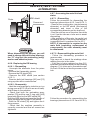
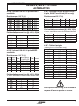
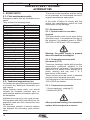
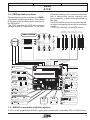
1
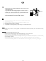
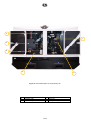
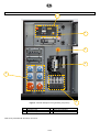
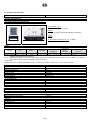
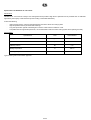
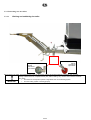
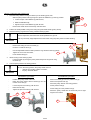
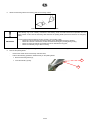
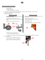
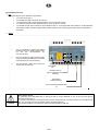
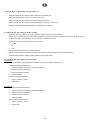
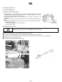
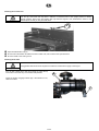
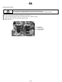
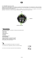
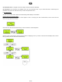
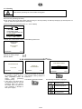
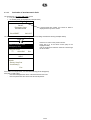
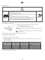
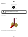
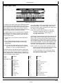
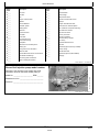
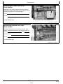
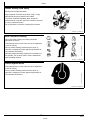
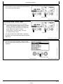
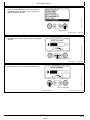
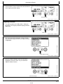
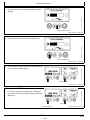
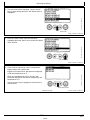
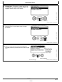
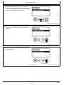
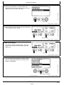
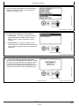
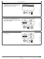
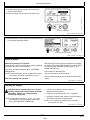
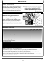
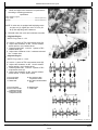
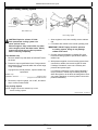
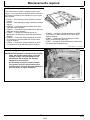
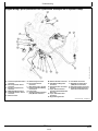
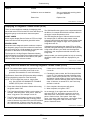
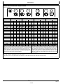
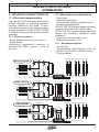
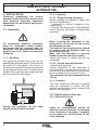
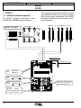
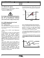
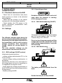
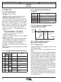
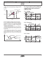
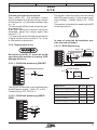
LEROY-SOMER
Installation and maintenance
3971 en - 2010.11 / f
R438
A.V.R.
The best response times are obtained at the
limit of the instability. If no stable position
can be obtained, try disconnecting or replacing the ST2 jumper (normal/fast).
h) Check LAM operation : ST5 closed.
i) Vary the frequency (speed) around 48 or
58 Hz according to the operating frequency,
and check the change in voltage from that
observed previously (~ 15%).
j) Readjust the speed of the unit to its rated
no-load value.
Adjustments in parallel operation
Before any intervention on the alternator, make sure that the speed droop is
identical for all engines.
k) Preset for parallel operation (with C.T.
connected to S1, S2)
- Potentiometer P1 (quadrature droop) in
centre position.
Apply the rated load (cos ϕ = 0.8 inductive).
The voltage should drop by 2 to 3%. If it increases, check that V and W and also S1
and S2 have not been reversed.
l) The no-load voltages should be identical
for all the alternators intended to run in parallel.
- Couple the machines in parallel.
- By adjusting the speed, try to obtain 0 KW
power exchange.
- By altering the voltage setting P2 on one of
the machines, try to cancel (or minimise) the
current circulating between the machines.
- From now on, do not touch the voltage settings.
m) Apply the available load (the setting is only
correct if a reactive load is available)
- By altering the speed, match the kW (or divide the rated power of the units proportionally)
- By altering the quadrature droop potentiometer P1, match or divide the currents.
3.2.2 - Max. excitation setting (excitation
ceiling)
Depending on
the mains frequency
Max. excitation
ST3
X2
50Hz 60Hz
Z1
X1
Z2
E+
R 438
P3
E0V
110 V
P2
220 V
ST4
380 V
Main
(50/60 Hz supply)
48 V
P5
A
–
A
+
Field
~ 5 ohms
10 A CC/DC
110/220/380 V
D
Voltage
Static adjustment of the current limit,
potentiometer P5 (factory setting: 7.5 A,
fuse rating: 8 A - 10 seconds).
The maximum factory setting corresponds
to that of the excitation current required to
obtain a 3-phase short-circuit current of
approximately 3 IN at 50 Hz for industrial
power, unless otherwise specified(*).
A static method can be used to reduce this
value or adapt the Isc to the actual operating
power (derated machine), which is safer for
the alternator and the installation.
Disconnect power supply wires X1,X2 and
Z1,Z2 and the voltage reference
(0‑110V-220V-380V) on the alternator.
Connect the mains power supply using a
transformer (200-240V) as indicated
(X1,X2 : 48V). Install a 10A D.C. ammeter
in series with the exciter field. Turn P5 fully
anti-clockwise and activate the power
supply. If there is no output current from the
AVR, turn potentiometer P2 (voltage)
clockwise until the ammeter indicates a
stable current. Switch the power supply off,
then on again, turn P5 clockwise until the
required max. current is obtained (no more
than 8 A).
10
268/290