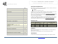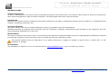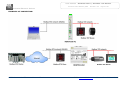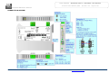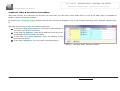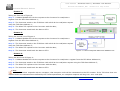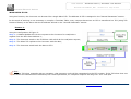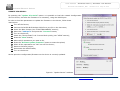
1
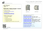
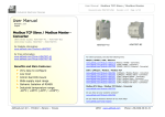
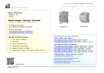
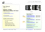
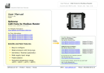
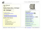
User Manual
Modbus Slave / Modbus TCP Master
Document code: MN67510_ENG
Revision 1.012
Page 1 of 26
Industrial Electronic Devices
User Manual
Revision 1.012
English
Modbus Slave / Modbus TCP Master Converter
(New Order Codes: HD67510-A1 – HD67510-B2)
(Old Order Codes: HD67510 – HD67510M)
HD67510-B2
HD67510-A1
for Website information:
www.adfweb.com?Product=HD67510
for Price information:
www.adfweb.com?Price=HD67510-A1
www.adfweb.com?Price=HD67510-B2
For others products, see also the following links:
Benefits and Main Features:
www.adfweb.com?Product=HD67118 (RS232 / RS485 - Converter)
www.adfweb.com?Product=HD67119 (USB / RS485 - Converter)
www.adfweb.com?Product=HD67038 (RS485 / RS232 / Ethernet - Converter)
RS232 / RS485 / USB / Ethernet
Very easy to configure
Low Cost
32mm Rail DIN mount
Wide supply input range
INDEX:
Galvanic Isolation of RS485
Industrial temperature range:
-40°C / +85°C (-40°F / +185°F)
UPDATED DOCUMENTATION
REVISION LIST
WARNING
TRADEMARKS
INDEX
WARRANTIES AND TECHNICAL
ADFweb.com Srl – IT31010 – Mareno – Treviso
CAN / CANopen / Modbus / Modbus TCP
www.adfweb.com?Product=HD67001
www.adfweb.com?Product=HD67502
www.adfweb.com?Product=HD67011
www.adfweb.com?Product=HD67012
www.adfweb.com?Product=HD67514
www.adfweb.com?Product=HD67515
(CANopen / Modbus Master - Converter)
(CANopen / Modbus Slave - Converter)
(CAN / Modbus Master - Converter)
(CAN / Modbus Slave - Converter)
(CAN / Modbus TCP Master – Converter)
(CAN / Modbus TCP Slave – Converter)
Modbus TCP Slave
/ Modbus RTU Master - Converter
Page
www.adfweb.com?Product=HD67507
2
Do you have an your2customer protocol?
2
2
Do you need to choose
3 a device? do you want help?
www.adfweb.com?Cmd=helpme
SUPPORT
4
www.adfweb.com?Product=HD67003
INFO: www.adfweb.com
Phone +39.0438.30.91.31
User Manual
Modbus Slave / Modbus TCP Master
Document code: MN67510_ENG
Revision 1.012
Page 2 of 26
Industrial Electronic Devices
INDEX:
UPDATED DOCUMENTATION:
INDEX
UPDATED DOCUMENTATION
REVISION LIST
WARNING
TRADEMARKS
SECURITY ALERT
EXAMPLES OF CONNECTION
CONNECTION SCHEME
CHARACTERISTICS
POWER SUPPLY
FUNCTION MODES
LEDS
ETHERNET
RS232
RS485
USE OF COMPOSITOR SW67510
NEW PROJECT / OPEN PROJECT
GENERAL PARAMETER
PING DEVICE
TRANSLATE TABLE NORMAL MODE
(TRANSLATE TABLE)
TRANSLATE TABLE ROUTING SLAVE
ADDRESS
WORK WITH FIX IP
UPDATE VIA SERIAL
UPDATE VIA UDP
MECHANICAL DIMENSIONS
ORDER CODE
ACCESSORIES
DISCLAIMER
OTHER REGULATIONS AND STANDARDS
WARRANTIES AND TECHNICAL SUPPORT
RETURN POLICY
PRODUCTS AND RELATED DOCUMENTS
ADFweb.com Srl – IT31010 – Mareno – Treviso
Page
2
2
2
2
2
3
4
5
7
8
9
10
11
11
12
13
13
14
15
16
18
20
21
22
24
24
24
25
25
26
26
26
Dear customer, we thank you for your attention and we remind you that you
need to check that the following document is:
Updated
Related to the product you own
To obtain the most recently updated document, note the “document code” that
appears at the top right-hand corner of each page of this document.
With this “Document Code” go to web page www.adfweb.com/download/ and
search for the corresponding code on the page. Click on the proper “Document
Code” and download the updates.
To obtain the updated documentation for the product that you own, note the
“Document Code” (Abbreviated written "Doc. Code" on the label on the product)
and download the updated from our web site www.adfweb.com/download/
REVISION LIST:
Revision
1.000
1.001
1.010
1.011
1.012
Date
06/02/2009
06/05/2010
04/09/2012
18/12/2012
24/01/2013
Author
Fl
Ml Dp
Fl
Fl
Nt
Chapter
All
All
All
All
All
Description
First release version
Revision
Software changed (v1.300)
Revision
Added new chapters
WARNING:
ADFweb.com reserves the right to change information in this manual about our
product without warning.
ADFweb.com is not responsible for any error this manual may contain.
TRADEMARKS:
All trademarks mentioned in this document belong to their respective owners.
INFO: www.adfweb.com
Phone +39.0438.30.91.31
User Manual
Modbus Slave / Modbus TCP Master
Document code: MN67510_ENG
Revision 1.012
Page 3 of 26
Industrial Electronic Devices
SECURITY ALERT:
GENERAL INFORMATION
To ensure safe operation, the device must be operated according to the instructions in the manual. When using the device are required for
each individual application, legal and safety regulation. The same applies also when using accessories.
INTENDED USE
Machines and systems must be designed so the faulty conditions do not lead to a dangerous situation for the operator (i.e. independent limit
switches, mechanical interlocks, etc.).
QUALIFIED PERSONNEL
The device can be used only by qualified personnel, strictly in accordance with the specifications.
Qualified personnel are persons who are familiar with the installation, assembly, commissioning and operation of this equipment and who
have appropriate qualifications for their job.
RESIDUAL RISKS
The device is state of the art and is safe. The instrument can represent a potential hazard if they are inappropriately installed and operated
by personnel untrained. These instructions refer to residual risks with the following symbol:
This symbol indicates that non-observance of the safety instructions is danger for people to serious injury or death and / or the
possibility of damage.
CE CONFORMITY
The declaration is made by us. You can send an email to [email protected] or give us a call if you need it.
ADFweb.com Srl – IT31010 – Mareno – Treviso
INFO: www.adfweb.com
Phone +39.0438.30.91.31
User Manual
Modbus Slave / Modbus TCP Master
Document code: MN67510_ENG
Revision 1.012
Page 4 of 26
Industrial Electronic Devices
EXAMPLES OF CONNECTION:
ADFweb.com Srl – IT31010 – Mareno – Treviso
INFO: www.adfweb.com
Phone +39.0438.30.91.31
User Manual
Modbus Slave / Modbus TCP Master
Document code: MN67510_ENG
Revision 1.012
Page 5 of 26
Industrial Electronic Devices
CONNECTION SCHEME:
Figure 1a: Connection Scheme for HD67510-A1, HD67510
ADFweb.com Srl – IT31010 – Mareno – Treviso
INFO: www.adfweb.com
Phone +39.0438.30.91.31
User Manual
Modbus Slave / Modbus TCP Master
Document code: MN67510_ENG
Revision 1.012
Page 6 of 26
Industrial Electronic Devices
Figure 1b: Connection Scheme for HD67510-B2, HD67510M
ADFweb.com Srl – IT31010 – Mareno – Treviso
INFO: www.adfweb.com
Phone +39.0438.30.91.31
User Manual
Modbus Slave / Modbus TCP Master
Document code: MN67510_ENG
Revision 1.012
Page 7 of 26
Industrial Electronic Devices
CHARACTERISTICS:
The “Modbus Slave / Modbus TCP Master – Converter” allows the following characteristics:
Opto-isolated RS485;
Choice possibility between RS232 or RS485 on Modbus RTU;
Ethernet 10Base-T / 100Base-T, autosensing for Modbus TCP ;
Mountable on 35mm Rail DIN;
Temperature range -40°C / +85°C;
EMS EN 61000-6-2.
To configure the Converter, use the available software that runs with Windows, called SW67510. It is downloadable on the site
www.adfweb.com and its operation is described in this document.
ADFweb.com Srl – IT31010 – Mareno – Treviso
INFO: www.adfweb.com
Phone +39.0438.30.91.31
User Manual
Modbus Slave / Modbus TCP Master
Document code: MN67510_ENG
Revision 1.012
Page 8 of 26
Industrial Electronic Devices
POWER SUPPLY:
The devices can be powered at 8…19V AC and 8…35V DC. The consumption depends to the code of the device. For more details see the two
tables below.
VAC
VDC
Vmin
Vmax
Vmin
Vmax
8V
19V
8V
35V
Consumption at 24V DC:
Device
Consumption [W/VA]
HD67510-A1
4
HD67510-B2
5
Warning: Not reverse the polarity power
HD67510-A1
HD67510-B2
ADFweb.com Srl – IT31010 – Mareno – Treviso
INFO: www.adfweb.com
Phone +39.0438.30.91.31
User Manual
Modbus Slave / Modbus TCP Master
Document code: MN67510_ENG
Revision 1.012
Page 9 of 26
Industrial Electronic Devices
FUNCTION MODES:
The devices has got two functions mode depending of the position ‘Jumper1’:
The first, without Jumper1 (factory setting), is used for the normal working of the device;
The second, with Jumper1, is used for upload the Project/Firmware into the device.
For the operations to follow for the updating, see ‘UPDATE DEVICE’ section.
According to the functioning mode, the LEDs will have specifics functions, see ‘LEDS’ section.
ADFweb.com Srl – IT31010 – Mareno – Treviso
INFO: www.adfweb.com
Phone +39.0438.30.91.31
User Manual
Modbus Slave / Modbus TCP Master
Document code: MN67510_ENG
Revision 1.012
Page 10 of 26
Industrial Electronic Devices
LEDS:
The devices has got four LEDs that are used to give information of the functioning status.
The various meanings of the LEDs are described in the table below.
LED
1: Device State (green)
2: Ethernet Link (green)
Normal Mode
Blinks slowly (~1Hz)
Boot Mode
Blinks quickly: Boot state
Blinks very slowly (~0.5Hz): update in progress
ON: Ethernet cable connected
ON: Ethernet cable connected
OFF: Ethernet cable disconnected
OFF: Ethernet cable disconnected
3: Modbus TCP data (green)
Change state when send a Modbus request
4: Modbus RTU data (green)
Change state when receive a Modbus request
ADFweb.com Srl – IT31010 – Mareno – Treviso
Blinks quickly: Boot state
Blinks very slowly (~0.5Hz): update in progress
Blinks quickly: Boot state
Blinks very slowly (~0.5Hz): update in progress
INFO: www.adfweb.com
Phone +39.0438.30.91.31
User Manual
Modbus Slave / Modbus TCP Master
Document code: MN67510_ENG
Revision 1.012
Page 11 of 26
Industrial Electronic Devices
ETHERNET:
The Ethernet connection must be made using Connector3 of HD67510-A1/HD67510-B2 with at least a Category 5E cable. The maximum
length of the cable should not exceed 100m. The cable has to conform to the T568 norms relative to connections in cat.5 up to 100 Mbps. To
connect the device to an Hub/Switch is recommended the use of a straight cable, to connect the device to a PC/PLC/other is recommended
the use of a cross cable.
RS232:
The connection from RS232 socket to a serial port (example one from a personal computer), must be made with a Null Modem cable (a
serial cable where the pins 2 and 3 are crossed). It is recommended that the RS232C Cable not exceed 15 meters.
The serial port is used for programming the device or for Modbus communication.
ADFweb.com Srl – IT31010 – Mareno – Treviso
INFO: www.adfweb.com
Phone +39.0438.30.91.31
User Manual
Modbus Slave / Modbus TCP Master
Document code: MN67510_ENG
Revision 1.012
Page 12 of 26
Industrial Electronic Devices
RS485:
For terminate the RS485 line with a 220Ω resistor it is necessary to insert the Jumper2 like in figure.
The maximum length of the cable should be 1200m (4000 feet).
Here some codes of cables:
Belden: p/n 8132 - 2x 28AWG stranded twisted pairs conductor + foil shield + braid shield;
Belden p/n 82842 - 2x 24AWG stranded twisted pairs conductor + foil shield + braid shield;
Tasker: p/n C521 - 1x 24AWG twisted pair conductor + foil shield + braid shield;
Tasker: p/n C522 - 2x 24AWG twisted pairs conductor + foil shield + braid shield.
ADFweb.com Srl – IT31010 – Mareno – Treviso
INFO: www.adfweb.com
Phone +39.0438.30.91.31
User Manual
Modbus Slave / Modbus TCP Master
Document code: MN67510_ENG
Revision 1.012
Page 13 of 26
Industrial Electronic Devices
USE OF COMPOSITOR SW67510:
To configure the “Modbus Slave / Morbus TCP Master - Converter”, use
the available software that runs with Windows, called SW67510. It is
downloadable on the site www.adfweb.com and its operation is
described in this document. (This manual is referenced to the last
version of the software present on our web site). The software works
with MSWindows (MS 2000, XP, Vista, Seven, 8; 32/64bit).
When launching the SW67507 the right window appears (Fig. 2).
Figure 2: Main window for SW67510
NEW PROJECT / OPEN PROJECT:
The “New Project” button creates the folder which contains the entire device configuration.
A device configuration can also be imported or exported:
To clone the configurations of a Programmable “Modbus Slave / Morbus TCP Master Converter” in order to configure another device in the same manner, it is necessary to
maintain the folder and all its contents;
To clone a project in order to obtain a different version of the project, it is sufficient to duplicate the
project folder with another name and open the new folder with the button “Open Project”.
ADFweb.com Srl – IT31010 – Mareno – Treviso
INFO: www.adfweb.com
Phone +39.0438.30.91.31
User Manual
Modbus Slave / Modbus TCP Master
Document code: MN67510_ENG
Revision 1.012
Page 14 of 26
Industrial Electronic Devices
GENERAL PARAMETER:
This section defines the fundamental communication parameters of two buses,
Modbus TCP and Modbus RTU.
By pressing the “General Parameter” button from the main window for SW67510
(Fig. 2) the window “General Parameter” appears (Fig. 3).
The means for the fields of “MODBUS TCP” are:
In the field “IP Address” insert the IP address that you want to give to the
Master Modbus TCP;
In the field “Subnet Mask” insert the Subnet Mask;
In field “Gateway” insert the Defualt Gateway IP address for use the
Converter in WAN or Internet. For enable this feature is necessary to check
the Gateway option.
In the field “Port” insert the number of port;
If the field “Don’t disconnect the socket” is checked, when the gateway
receives the TCP response it does not disconnect the opened socket (open
the socket only at the first RTU request and then the socket remains
opened); otherwise for every RTU requests the gateway opens the socket
and when it receives the TCP response it closes it;
If the field “Normal Mode (Translate Table)” is checked, the address of
RTU request is compared with the list defined in the “Translate Table”
Figure 3: “General Parameter” window
section; and if is present the Converter sends the request in TCP using the
IP address and the Address TCP defined in that table (see ‘TRANSLATE TABLE NORMAL MODE (TRANSLATE TABLE)’ section);
If the field “Work with Fix IP” is checked, the gateway does not see the “Translate Table” but it sends every request to a fixed IP
defined in the field below (see ‘WORK WITH FIX IP’ section);
If the field “Routing Slave Address” is checked, the address of RTU request is compared with the list defined in the “Translate
Table” section; and if is present the Converter sends the request in TCP using the IP address and the TCP slave address (see
‘TRANSLATE TABLE ROUTING SLAVE ADDRESS’ section);
ADFweb.com Srl – IT31010 – Mareno – Treviso
INFO: www.adfweb.com
Phone +39.0438.30.91.31
User Manual
Modbus Slave / Modbus TCP Master
Document code: MN67510_ENG
Revision 1.012
Page 15 of 26
Industrial Electronic Devices
The means for the fields of “MODBUS RTU” are:
In the field “Address” the address of the device is defined. This field can be compiled only if is checked the field “Normal Mode
(Translate Table)” or “Work with Fix IP” ;
In the field “Baud rate” the velocity of the Modbus RTU is defined;
In the field “Parity” the Modbus RTU parity is defined. It is possible to use “NONE” or “EVEN” or “ODD” parity;
In the field “Timeout (ms)” insert the maximum time that the device has to attend for the answer from the Slave interrogated;
If the field “RS232” is checked the serial line in use for Modbus RTU is the RS232; otherwise is the “RS485”.
PING DEVICE:
If it is necessary to do a Ping on the net, before pressing the “Ping Device” button insert a value in the field on the right and then press the
button. To use this feature in Vista and 7 you have to open the software with Administrator right.
Note:
In order to do this, the Converter must be in Normal Mode.
ADFweb.com Srl – IT31010 – Mareno – Treviso
INFO: www.adfweb.com
Phone +39.0438.30.91.31
User Manual
Modbus Slave / Modbus TCP Master
Document code: MN67510_ENG
Revision 1.012
Page 16 of 26
Industrial Electronic Devices
TRANSLATE TABLE NORMAL MODE (TRANSLATE TABLE):
Using this function, the Converter can be seen like a single Slave RTU. The Address of RTU is assigned in the “General Parameter” section.
By pressing the “Translate Table” button from the main window for SW67510 (Fig. 2) the window “Set Translate Table” appears (Fig. 4).
The data of the columns have the following meanings:
In the field “Data Type” it is possible to select the type of
data that is being considered;
In the field “Address RTU” insert the virtual address of
the present data in a device in the TCP Modbus;
In the field “Address Device TCP” insert the IP address
of the device on the Modbus TCP that contains the data;
In the field “Address TCP” insert the address of the data
on the TCP device;
In the field “N° Point” insert the number of consecutive
Figure 4: “Set Translate Table” window
data that you want to configure. For example, you create
Address TCP=44, Address RTU=30 and N° point = 3, the following gets set-up automatically: addresses TCP 44, 45, 46 and the
variables RTU 30, 31, 32;
In the field “Mnemonic” you can insert a brief description.
ADFweb.com Srl – IT31010 – Mareno – Treviso
INFO: www.adfweb.com
Phone +39.0438.30.91.31
User Manual
Modbus Slave / Modbus TCP Master
Document code: MN67510_ENG
Revision 1.012
Page 17 of 26
Industrial Electronic Devices
EXAMPLE 1:
Taking the first row of Figure 4:
Step 1: A Master Modbus RTU do the request to the Converter for read the “Coil
Status” address 1;
Step 2: The Converter sends to the TCP Slave 192.168.2.18 the read request of
“Coil Status” address 1;
Step 3: The Slave TCP replies to the Converter with the data;
Step 4: The Converter sends back the data on RTU.
EXAMPLE 2:
Taking the second row of Figure 4:
Step 1: A Master Modbus RTU do the request to the Converter for read the “Input
Status” address 40 for 8 consecutive points;
Step 2: The Converter sends to the TCP Slave 192.168.2.18 the read request of
“Input Status” address 55 for 8 consecutive points;
Step 3: The Slave TCP replies to the Converter with the data;
Step 4: The Converter sends back the data on RTU.
Figure 5: Chart of Request data from Modbus TCP
EXAMPLE 3:
Taking the third row of Figure 4:
Step 1: A Master Modbus RTU do the request to the Converter for read the “Holding Register” address 40 for 3 consecutive points;
Step 2: The Converter sends to the TCP Slave 192.168.2.19 the read request of “Holding Register” address 44 for 3 consecutive points;
Step 3: The Slave TCP replies to the Converter with the data;
Step 4: The Converter sends back the data on RTU.
Note:
If the TCP slave responds with an exception, that exception code will be transmitted to the RTU master. If the TCP slave does not
respond within the estimated time defined by the Timeout parameter, an exception response will be given: error code $36.
ADFweb.com Srl – IT31010 – Mareno – Treviso
INFO: www.adfweb.com
Phone +39.0438.30.91.31
User Manual
Modbus Slave / Modbus TCP Master
Document code: MN67510_ENG
Revision 1.012
Page 18 of 26
Industrial Electronic Devices
TRANSLATE TABLE ROUTING SLAVE ADDRESS:
Using this function, the Converter can be seen like more than one Slave RTU. Each Slave RTU is a row of the table, and it is possible to
assign to which TCP device is linked.
By pressing the “Translate Table” button from the main window for SW67510 (Fig. 2) the window “FRouting_Slave_Address” appears (Fig.
6).
The data of the columns have the following meanings:
In the field “RTU Slave Address” insert the virtual address of
the device (will be the Converter);
In the field “IP Address” insert the IP address of the device on
the Modbus TCP that contains the data;
In the field “TCP Slave Address” insert the address of the
device at TCP device;
In the field “Mnemonic” you can insert a brief description.
Figure 6: “FRouting_Slave_Address” window
ADFweb.com Srl – IT31010 – Mareno – Treviso
INFO: www.adfweb.com
Phone +39.0438.30.91.31
User Manual
Modbus Slave / Modbus TCP Master
Document code: MN67510_ENG
Revision 1.012
Page 19 of 26
Industrial Electronic Devices
EXAMPLE 1:
Taking the first row of Figure 6:
Step 1: A Master Modbus RTU do the request to the Converter for read/write a
register from the RTU Slave Address 1;
Step 2: The Converter sends to the TCP Slave 192.168.2.18 the read/write request
using the TCP Slave Address 1;
Step 3: The Slave TCP replies to the Converter with the data;
Step 4: The Converter sends back the data on RTU.
EXAMPLE 2:
Taking the second row of Figure 4:
Step 1: A Master Modbus RTU do the request to the Converter for read/write a
register from the RTU Slave Address 2;
Step 2: The Converter sends to the TCP Slave 192.168.2.18 the read/write request
using the TCP Slave Address 5;
Step 3: The Slave TCP replies to the Converter with the data;
Step 4: The Converter sends back the data on RTU.
Figure 7: Chart of Request data from Modbus TCP
EXAMPLE 3:
Taking the third row of Figure 4:
Step 1: A Master Modbus RTU do the request to the Converter for read/write a register from the RTU Slave Address 10;
Step 2: The Converter sends to the TCP Slave 192.168.2.20 the read/write request using the TCP Slave Address 5;
Step 3: The Slave TCP replies to the Converter with the data;
Step 4: The Converter sends back the data on RTU.
Note:
If the TCP slave responds with an exception, that exception code will be transmitted to the RTU master. If the TCP slave does not
respond within the estimated time defined by the Timeout parameter, an exception response will be given: error code $36.
ADFweb.com Srl – IT31010 – Mareno – Treviso
INFO: www.adfweb.com
Phone +39.0438.30.91.31
User Manual
Modbus Slave / Modbus TCP Master
Document code: MN67510_ENG
Revision 1.012
Page 20 of 26
Industrial Electronic Devices
WORK WITH FIX IP:
Using this function, the Converter can be seen like a single Slave RTU. The Address of RTU is assigned in the “General Parameter” section.
In this mode of working is not necessary to compile a Translate Table; every request that arrives on RTU is transferred on TCP (using TCP
format of frame) to the Slave with the IP address defined in the “General Parameter” section.
EXAMPLE 1:
Using the configuration of Figure 3:
Step 1: A Master Modbus RTU do the request to the Converter for read/write a
register from the RTU Slave Address 1;
Step 2: The Converter sends to the TCP Slave 192.168.2.18 the read/write request;
Step 3: The Slave TCP replies to the Converter with the data;
Step 4: The Converter sends back the data on RTU.
Note:
If the TCP slave responds with an exception, that exception code will be transmitted to the RTU master. If the TCP slave does not
respond within the estimated time defined by the Timeout parameter, an exception response will be given: error code $36.
ADFweb.com Srl – IT31010 – Mareno – Treviso
INFO: www.adfweb.com
Phone +39.0438.30.91.31
User Manual
Modbus Slave / Modbus TCP Master
Document code: MN67510_ENG
Revision 1.012
Page 21 of 26
Industrial Electronic Devices
UPDATE VIA SERIAL:
By pressing the “Update Via Serial” button it is possible to load the created Configuration
into the device, and also the Firmware if is necessary, using the RS232 port.
In order to load the parameters or update the firmware in the device, follow these
instructions:
Turn off the Device;
Connect the RS232 Null Modem Cable form your PC to the Converter;
Insert the Boot Jumper (see “FUNCTION MODES” section);
Select the “COM port” and press the “Connect” button;
Turn on the device;
Check the “Device State” Led. It must blink quickly (see “LEDS” section);
Press the “Next” button;
Select which operations you want to do.
Press the “Execute update firmware” button to start the upload;
When all the operations are “OK” turn off the device;
Remove the Boot jumper;
Disconnect the RS232 Cable;
Turn on the device.
At this point the configuration/firmware on the device is correctly updated.
Figure 8: “Update Device” windows
ADFweb.com Srl – IT31010 – Mareno – Treviso
INFO: www.adfweb.com
Phone +39.0438.30.91.31
User Manual
Modbus Slave / Modbus TCP Master
Document code: MN67510_ENG
Revision 1.012
Page 22 of 26
Industrial Electronic Devices
UPDATE VIA UDP:
By pressing the “Update Via UDP” button it is possible to load the created Configuration into the
device, and also the Firmware if is necessary, using the Ethernet port.
If you don’t know the actual IP address of the device you have to use this procedure:
Turn off the Device;
Insert the Boot Jumper (see “FUNCTION MODES” section);
Insert the IP “192.168.2.66”;
Turn on the device;
Press the “Ping” button, must appear “Device Found!”;
Press the “Next” button;
Select which operations you want to do;
Press the “Execute update firmware” button to start the upload;
When all the operations are “OK” turn off the Device;
Remove the Boot jumper;
Turn on the device.
At this point the configuration/firmware on the device is correctly updated.
If you know the actual IP address of the device you have to use this procedure:
Turn on the Device with the Ethernet cable inserted;
Insert the actual IP of the Gateway;
Press the “Ping” button, must appear “Device Found!”;
Press the “Next” button;
Select which operations you want to do;
Press the “Execute update firmware” button to start the upload;
When all the operations are “OK” the device automatically goes at
Normal Mode.
At this point the configuration/firmware on the device is correctly update.
Figure 9: “Update device” windows
ADFweb.com Srl – IT31010 – Mareno – Treviso
INFO: www.adfweb.com
Phone +39.0438.30.91.31
User Manual
Modbus Slave / Modbus TCP Master
Document code: MN67510_ENG
Revision 1.012
Page 23 of 26
Industrial Electronic Devices
Note:
When you install a new version of the software it is better if the first time you do the update of the Firmware in the HD67510-A1 or
HD67510-B2 device.
Note:
When you receive the device, for the first time, you have to update also the Firmware in the HD67510-A1 or HD67510-B2 device.
Warning:
If the Fig. 10 appears when you try to do the Update before require assistance try
these points:
Check if the serial COM port selected is the correct one;
Check if the serial cable is connected between the PC and the device;
Try to repeat the operations for the updating;
If you are using a USBRS232 converter try with a native COM port or change
the converter;
Try to repeat the operations for the updating;
Try with another PC;
Try to restart the PC;
If you are using the program inside a Virtual Machine, try to use in the main
Operating System;
If you are using Windows Seven or Vista, make sure that you have the
administrator privileges;
Take attention at Firewall lock.
Figure 10: “Protection” windows
In the case of HD67510-A1 or HD67510-B2 you have to use the software “SW67510”:
www.adfweb.com\download\filefold\SW67510.zip.
Note:
The "Update via UDP" can be used only with Hardware HD67510-A1 or HD67510-B2, and only with Software version from 1.200;
The "Update via TCP" can be used only with Hardware HD67510 or HD67510M, and only with Software version up to 1.100;
The "Update via Serial" can be used with all hardware, and with all Software versions.
ADFweb.com Srl – IT31010 – Mareno – Treviso
INFO: www.adfweb.com
Phone +39.0438.30.91.31
User Manual
Modbus Slave / Modbus TCP Master
Document code: MN67510_ENG
Revision 1.012
Page 24 of 26
Industrial Electronic Devices
MECHANICAL DIMENSIONS:
Figure 11: Mechanical dimensions scheme for HD67510-A1
(and Old Model HD67510)
Figure 12: Mechanical dimensions scheme for HD67510-B2
(and Old Model HD67510M)
ORDER CODES:
Order Code: HD67510-A1 -
Modbus Slave / Modbus TCP Master - Converter ( Housing type: A, Terminal Blocks Connectors )
Order Code: HD67510-B2 -
Modbus Slave / Modbus TCP Master - Converter ( Housing type: B, Terminal Blocks Connectors )
ACCESSORIES:
Order Code: AC34107
-
Null Modem Cable Fem/Fem DSub 9 Pin 1,5 m
Order Code: AC34114
-
Null Modem Cable Fem/Fem DSub 9 Pin 5 m
Order Code: AC34001
-
Rail DIN - Power Supply 220/240V AC 50/60Hz – 12 V AC
Order Code: AC34002
-
Rail DIN - Power Supply 110V AC 50/60Hz – 12 V AC
ADFweb.com Srl – IT31010 – Mareno – Treviso
INFO: www.adfweb.com
Phone +39.0438.30.91.31
User Manual
Modbus Slave / Modbus TCP Master
Document code: MN67510_ENG
Revision 1.012
Page 25 of 26
Industrial Electronic Devices
DISCLAIMER
All technical content within this document can be modified without notice. The content of the document content is a recurring audit.
For losses due to fire, earthquake, third party access or other accidents, or intentional or accidental abuse, misuse, or use under abnormal
conditions repairs are charged to the user. ADFweb.com S.r.l. will not be liable for accidental loss of use or inability to use this product, such
as loss of business income. ADFweb.com S.r.l. shall not be liable for consequences of improper use.
OTHER REGULATIONS AND STANDARDS
WEEE INFORMATION
Disposal of old electrical and electronic equipment (as in the European Union and other European countries with separate
collection systems).
This symbol on the product or on its packaging indicates that this product may not be treated as household rubbish. Instead, it
should be taken to an applicable collection point for the recycling of electrical and electronic equipment. If the product is disposed
correctly, you will help prevent potential negative environmental factors and human health, which could otherwise be caused by
inappropriate disposal. The recycling of materials will help to conserve natural resources. For more information about recycling this
product, please contact your local city office, your household waste disposal service or the shop where you purchased the product.
RESTRICTION OF HAZARDOUS SUBSTANCES DIRECTIVE
The device respects the 2002/95/EC Directive on the restriction of the use of certain hazardous substances in electrical
and electronic equipment (commonly referred to as Restriction of Hazardous Substances Directive or RoHS).
CE MARKING
The product conforms with the essential requirements of the applicable EC directives.
ADFweb.com Srl – IT31010 – Mareno – Treviso
INFO: www.adfweb.com
Phone +39.0438.30.91.31
User Manual
Modbus Slave / Modbus TCP Master
Document code: MN67510_ENG
Revision 1.012
Page 26 of 26
Industrial Electronic Devices
WARRANTIES AND TECHNICAL SUPPORT:
For fast and easy technical support for your ADFweb.com SRL products, consult our internet support at www.adfweb.com.
Otherwise contact us at the address [email protected]
RETURN POLICY:
If while using your product you have any problem and you wish to exchange or repair it, please do the following:
1) Obtain a Product Return Number (PRN) from our internet support at www.adfweb.com. Together with the request, you need to provide detailed information
about the problem.
2) Send the product to the address provided with the PRN, having prepaid the shipping costs (shipment costs billed to us will not be accepted).
If the product is within the warranty of twelve months, it will be repaired or exchanged and returned within three weeks. If the product is no longer under warranty,
you will receive a repair estimate.
PRODUCTS AND RELATED DOCUMENTS:
Part
Description
URL
HD67118
Converter RS232 to RS485 Isolated
www.adfweb.com?Product=HD67118
HD67119
Converter USB 2.0 to RS485 Isolated
www.adfweb.com?Product=HD67119
HD67507
Gateway Modbus TCP Server to RTU Master
www.adfweb.com?Product=HD67507
HD67510
Gateway Modbus TCP Client to RTU Slave
www.adfweb.com?Product=HD67510
ADFweb.com Srl – IT31010 – Mareno – Treviso
INFO: www.adfweb.com
Phone +39.0438.30.91.31