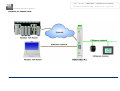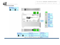
1
User Manual
CANopen / Modbus TCP Slave
Document code: MN67505_ENG
Revision 3.001
Page 1 of 39
Industrial Electronic Devices
User Manual
Revision 3.001
English
CANopen / Modbus TCP Slave - Converter
(Order Code: HD67505-A1 – HD67505-B2)
For Website information:
www.adfweb.com?Product=HD67505
For Price information:
www.adfweb.com?Price=HD67505-A1
www.adfweb.com?Price=HD67505-B2
Benefits and Main Features:
Very easy to configure
Low cost
Rail mountable
Wide supply input range
Galvanic isolation
Temperature range: -40°C/+85°C (-40°F/+185°F)
HD67505-A1
HD67505-B2
For other Gateways / Bridges:
CANopen to Modbus / DeviceNET
See also the following links:
www.adfweb.com?product=HD67001
www.adfweb.com?product=HD67502
www.adfweb.com?Product=HD67504
www.adfweb.com?product=HD67134
(Modbus RTU Master)
(Modbus RTU Slave)
(Modbus TCP Master)
(DeviceNET)
CAN bus to Modbus
See also the following links:
www.adfweb.com?product=HD67011
www.adfweb.com?product=HD67012
www.adfweb.com?product=HD67514
www.adfweb.com?product=HD67515
(Modbus
(Modbus
(Modbus
(Modbus
RTU Master)
RTU Slave)
TCP Master)
TCP Slave)
Do you have an your customer protocol?
See the following links:
www.adfweb.com?Product=HD67003
Do you need to choose a device? do you want help?
User Manual
ADFweb.com S.r.l.
Ask it to the following link:
www.adfweb.com?Cmd=helpme
User Manual
CANopen / Modbus TCP Slave
Document code: MN67505_ENG
Revision 3.001
Page 2 of 39
Industrial Electronic Devices
INDEX:
INDEX
UPDATED DOCUMENTATION
REVISION LIST
WARNING
TRADEMARKS
SECURITY ALERT
EXAMPLES OF CONNECTION
CONNECTION SCHEME
CHARACTERISTICS
CONFIGURATION
POWER SUPPLY
FUNCTION MODES
LEDS
ETHERNET
CANOPEN
USE OF COMPOSITOR SW67505
NEW PROJECT / OPEN PROJECT
SOFTWARE OPTIONS
SET COMMUNICATION
SET SDO CLIENT
SET SDO SERVER
SET EMERGENCY
DEFINE EMERGENCY
SET RECEIVE PDO
DEFINE PDO
SET TRANSMIT PDO
DEFINE PDO
SET NODEGUARDING
UPDATE DEVICE
MECHANICAL DIMENSIONS
ORDER CODE
ACCESSORIES
DISCLAIMER
OTHER REGULATIONS AND STANDARDS
WARRANTIES AND TECHNICAL SUPPORT
RETURN POLICY
ADFweb.com S.r.l.
UPDATED DOCUMENTATION:
Page
2
2
2
2
2
3
4
5
7
7
8
9
10
11
12
13
14
15
16
18
22
24
25
26
28
29
31
32
33
36
37
37
38
38
39
39
Dear customer, we thank you for your attention and we remind you that you
need to check that the following document is:
Updated
Related to the product you own
To obtain the most recently updated document, note the “document code” that
appears at the top right-hand corner of each page of this document.
With this “Document Code” go to web page www.adfweb.com/download/ and
search for the corresponding code on the page. Click on the proper “Document
Code” and download the updates.
REVISION LIST:
Revision
2.100
2.101
3.000
3.001
Date
12/12/2012
07/02/2013
25/07/2014
05/08/2014
Author
Dp
Nt
Ff
Ff
Chapter
All
All
All
All
Description
Add NodeGuard
Added new chapters
New hardware version
Revision
WARNING:
ADFweb.com reserves the right to change information in this manual about our
product without warning.
ADFweb.com is not responsible for any error this manual may contain.
TRADEMARKS:
All trademarks mentioned in this document belong to their respective owners.
User Manual
CANopen / Modbus TCP Slave
Document code: MN67505_ENG
Revision 3.001
Page 3 of 39
Industrial Electronic Devices
SECURITY ALERT:
GENERAL INFORMATION
To ensure safe operation, the device must be operated according to the instructions in the manual. When using the device are required for
each individual application, legal and safety regulation. The same applies also when using accessories.
INTENDED USE
Machines and systems must be designed so the faulty conditions do not lead to a dangerous situation for the operator (i.e. independent limit
switches, mechanical interlocks, etc.).
QUALIFIED PERSONNEL
The device can be used only by qualified personnel, strictly in accordance with the specifications.
Qualified personnel are persons who are familiar with the installation, assembly, commissioning and operation of this equipment and who
have appropriate qualifications for their job.
RESIDUAL RISKS
The device is state of the art and is safe. The instrument can represent a potential hazard if they are inappropriately installed and operated
by personnel untrained. These instructions refer to residual risks with the following symbol:
This symbol indicates that non-observance of the safety instructions is danger for people to serious injury or death and / or the
possibility of damage.
CE CONFORMITY
The declaration is made by us. You can send an email to [email protected] or give us a call if you need it.
ADFweb.com S.r.l.
User Manual
CANopen / Modbus TCP Slave
Document code: MN67505_ENG
Industrial Electronic Devices
EXAMPLE OF CONNECTION:
ADFweb.com S.r.l.
Revision 3.001
Page 4 of 39
User Manual
CANopen / Modbus TCP Slave
Document code: MN67505_ENG
Industrial Electronic Devices
CONNECTION SCHEME:
Figure 1a: Connection Scheme for HD67505-A1
ADFweb.com S.r.l.
Revision 3.001
Page 5 of 39
User Manual
CANopen / Modbus TCP Slave
Document code: MN67505_ENG
Industrial Electronic Devices
Figure 1b: Connection Scheme for HD67505-B2
ADFweb.com S.r.l.
Revision 3.001
Page 6 of 39
User Manual
CANopen / Modbus TCP Slave
Document code: MN67505_ENG
Industrial Electronic Devices
CHARACTERISTICS:
The “CANopen / Modbus TCP Slave – Converter” allows the following characteristics:
two-directional information between networks CAN and Modbus;
electrical isolation between two Buses;
Mountable on Rail DIN;
Temperature range from -40°C to +85°C.
This device is able to manage a maximum of ten simultaneous connections at Modbus TCP side.
CONFIGURATION:
You need Compositor SW67505 software on your PC in order to perform the following:
Define the parameter of CANopen;
Define the parameter of Modbus TCP;
Define that the SDO of the CANopen are accessible from Modbus;
Define how to update SDO in CANopen from Modbus;
Define that the EMCY of the CANopen are accessible from Modbus;
Define how and which EMCY generated in CANopen can be filtered;
Define which and how the PDO of CANopen are accessible from Modbus;
Update the new configurations of the device;
.
ADFweb.com S.r.l.
Revision 3.001
Page 7 of 39
User Manual
CANopen / Modbus TCP Slave
Document code: MN67505_ENG
Industrial Electronic Devices
POWER SUPPLY:
The devices can be powered at 8…24V AC and 12…35V DC. For more details see the two tables below.
VAC
VDC
Vmin
Vmax
Vmin
Vmax
8V
24V
12V
35V
Consumption at 24V DC:
Device
HD67505-A1
3.5
HD67505-B2
3.5
Caution: Not reverse the polarity power
HD67505-A1
ADFweb.com S.r.l.
Consumption [W/VA]
HD67505-B2
Revision 3.001
Page 8 of 39
User Manual
CANopen / Modbus TCP Slave
Document code: MN67505_ENG
Revision 3.001
Industrial Electronic Devices
FUNCTION MODES:
The device has got two function modes depending on the position of the ‘Dip2 of Dip-Switch A’:
The first, with ‘Dip2 of Dip-Switch A’ at “OFF” position, is used for the normal working of the device.
The second, with ‘Dip2 of Dip-Switch A’ at “ON” position, is used for uploading the Project and/or Firmware.
For the operations to follow for the updating, see ‘UPDATE DEVICE’ section.
According to the functioning mode, the LEDs will have specific functions, see ‘LEDS’ section.
Warning:
Dip1 of ‘Dip-Switch A’ must be at ON position to work even if the Ethernet cable is not inserted.
ADFweb.com S.r.l.
Page 9 of 39
User Manual
CANopen / Modbus TCP Slave
Document code: MN67505_ENG
Revision 3.001
Page 10 of 39
Industrial Electronic Devices
LEDS:
The devices has got four (five for HD67505-B2) LEDs that are used to give information of the functioning status.
The various meanings of the LEDs are described in the table below.
LED
1: CANopen Communication
(green)
2: Ethernet Link (green)
Normal Mode
Blinks when CANopen frames are received
Blinks quickly: Boot state
Blinks very slowly (~0.5Hz): update in progress
ON: Ethernet cable connected
ON: Ethernet cable connected
OFF: Ethernet cable disconnected
OFF: Ethernet cable disconnected
3: Modbus Communication
(green)
Blinks when Modbus TCP frames are received
4: Device State (yellow)
Blinks slowly (~1Hz)
5: Not used (yellow) (Present
only on HD67505-B2)
OFF
ADFweb.com S.r.l.
Boot Mode
Blinks quickly: Boot state
Blinks very slowly (~0.5Hz): update in progress
Blinks quickly: Boot state
Blinks very slowly (~0.5Hz): update in progress
Blinks quickly: Boot state
Blinks very slowly (~0.5Hz): update in progress
User Manual
CANopen / Modbus TCP Slave
Document code: MN67505_ENG
Revision 3.001
Page 11 of 39
Industrial Electronic Devices
ETHERNET:
The Ethernet connection must be made using Connector5 of HD67505-A1/HD67505-B2 with at least a Category 5E cable. The maximum
length of the cable should not exceed 100m. The cable has to conform to the T568 norms relative to connections in cat.5 up to 100 Mbps. To
connect the device to a Hub/Switch the use of a straight cable is recommended. To connect the device to a PC/PLC/other the use of a cross
cable is recommended.
ADFweb.com S.r.l.
User Manual
CANopen / Modbus TCP Slave
Document code: MN67505_ENG
Revision 3.001
Page 12 of 39
Industrial Electronic Devices
CANopen:
For terminating the CANopen line with a 120Ω resistor it is necessary that the Dip1 of ‘Dip-Switch C’ is at ON position (for the HD67505-A1)
and that the Dip2 of ‘Dip-Switch C’ is at ON position (for the HD67505-B2).
Cable characteristics:
ADFweb.com S.r.l.
DC parameter:
Impedance
70
Ohm/m
AC parameters:
Impedance
Delay
120 Ohm/m
5 ns/m
Length
Baud Rate [bps]
10 K
20 K
50 K
100 K
125 K
250 K
500 K
800 K
1000 K
Length MAX [m]
5000
2500
1000
650
500
250
100
50
25
User Manual
CANopen / Modbus TCP Slave
Document code: MN67505_ENG
Revision 3.001
Page 13 of 39
Industrial Electronic Devices
USE OF COMPOSITOR SW67505:
To configure the Converter, use the available software that runs with Windows called SW67505. It is downloadable on the site
www.adfweb.com and its operation is described in this document. (This manual is referenced to the last version of the software present on
our web site). The software works with MSWindows (XP, Vista, Seven, 8; 32/64bit).
When launching the SW67515, the window below appears (Fig. 2).
Note:
It is necessary to have installed .Net Framework 4.
Figure 2: Main window for SW67505
ADFweb.com S.r.l.
User Manual
CANopen / Modbus TCP Slave
Document code: MN67505_ENG
Industrial Electronic Devices
NEW CONFIGURATION / OPEN CONFIGURATION:
The “New Configuration” button creates the folder which contains the entire device’s configuration.
A device’s configuration can also be imported or exported:
To clone the configurations of a programmable “CANopen / Modbus TCP Slave Converter” in order to configure another device in the same manner, it is necessary
to maintain the folder and all its contents;
To clone a project in order to obtain a different version of the project, it is sufficient
to duplicate the project folder with another name and open the new folder with the
button “Open Configuration”.
ADFweb.com S.r.l.
Revision 3.001
Page 14 of 39
User Manual
CANopen / Modbus TCP Slave
Document code: MN67505_ENG
Revision 3.001
Page 15 of 39
Industrial Electronic Devices
SOFTWARE OPTIONS:
By pressing the “Settings” (
compositor.
) button there is the possibility to change the language of the software and check the updatings for the
In the section “Language” it is possible to change the language of the
software.
In the section “Connection Options”, it is possible to check if there are some
updatings of the software compositor in ADFweb.com website.
Checking the option “Check Software Update at Start of Program”, the
SW67505 check automatically if there are updatings when it is launched.
ADFweb.com S.r.l.
User Manual
CANopen / Modbus TCP Slave
Document code: MN67505_ENG
Revision 3.001
Page 16 of 39
Industrial Electronic Devices
SET COMMUNICATION:
This section defines the fundamental communication parameters of two Buses, CANopen and Modbus
TCP.
By pressing the “Set Communication” button from the main window for SW67505 (Fig. 2) the window
“Set communication” appears (Fig. 3).
This window is divided in two sections, one for configure the CANopen Network and the other for the
Modbus TCP.
In the section “Select Device” it is possible to select the type of converter used:
Device till April 2014 (with Jumper);
Device from May 2014 (with Dip-Switches).
I
The means for the fields for the “CANopen” are:
In the field “Device ID” the ID of the CANopen side is defined;
In the field “Baud Rate” the baudrate of the CAN is defined;
In the field “Set Operational State at Start-Up” the state of the CANopen is defined. I.e. If it is
checked the board starts in Operational State, else it starts in Pre-Operational;
In the field “Network Start at Start-Up” the state of the CANopen network is defined. I.e. If it
is checked the board sends a command to set the Operational State of all the devices present in
the network, after the time defined in the “Delay” field;
In the field “Delay (s)” the delay before sending the “Start” command for the CANopen is
defined;
In the field “SDO Client TimeOut (1/10 ms)” the maximum time that the device attends for
the answer from the Slave interrogated is defined;
If the field “Set CANopen State on Modbus” is set, it is possible to send the Modbus command
(sender word) of Operational/Pre-Operational State to one or all devices in CANopen network.
The sender word must have:
•
The high byte with the value of 1 for Operational or 2 for Pre-Operational.
•
The low byte must have the address of the device that is commanded to do the action
ADFweb.com S.r.l.
Figure 3: “Set Communication”
window
User Manual
CANopen / Modbus TCP Slave
Document code: MN67505_ENG
Revision 3.001
Page 17 of 39
Industrial Electronic Devices
(Operational/PreOperational), if you put zero all the devices present in CANopen
network take the state setted;
Example if you want to set the state of Operational to the device CANopen with
address 3, You must write the word “259” in the field “Add. Word Modbus”. Note:
259=0x0103.
•
In field “Add. Word Modbus” the address of Modbus register used for this operation is
defined.
If the field “Enable NodeGuard” is set, it is possible to enable the NodeGuard of CANopen Slave. The two fields (Modbus Address)
are used to indicate which Modbus registers using to save the state of the CANopen device. Every bit represents a CANopen device, if
the device is present, the bit is equal to 1 otherwise 0.
The means for the fields for “Modbus TCP Slave” are:
In the field “IP Address”, insert the IP address that you want to give to slave Modbus;
In the field “SubNet Mask” insert the SubNet Mask;
In the field “Gateway”, insert the default gateway that you want to use. This feature can be enabled or disabled pressing the Check
Box field. This feature is used for going out of the net;
In the field “Port” insert the number of the port.
ADFweb.com S.r.l.
User Manual
CANopen / Modbus TCP Slave
Document code: MN67505_ENG
Revision 3.001
Page 18 of 39
Industrial Electronic Devices
SET SDO CLIENT:
By pressing the “Set SDO Client” button from
the main window for SW67505 (Fig. 2) the
window “SDO Client Access Definition”
appears (Fig. 4).
The following objects can be defined in the
section “Set SDO Client”:
Which SDO of the CANopen
accessible from a Modbus TCP;
are
Which word of the Modbus are
accessible from a SDO of the CANopen.
The data of the columns have the following
Figure 4: “SDO Client Access Definition” window
meanings:
In the field “Address”, the Modbus register associated to the SDO is defined;
In the field “Hi Byte”, the correspondence between the Hi byte of the Modbus register and a SDO byte is defined (it can be set with
0, 1, 2, 3, 4);
o 1 = First byte of the SDO;
o 2 = Second byte of the SDO;
o 3 = Third byte of the SDO;
o 4 = Fourth byte of the SDO;
o 0 = No byte.
In the field “Lo Byte”, the correspondence between the Lo byte of the Modbus register and a SDO byte is defined (it can be set with
0, 1, 2, 3, 4);
o 1 = First byte of the SDO;
SDO Byte1
SDO Byte1
o 2 = Second byte of the SDO;
o 3 = Third byte of the SDO;
SDO Byte2
Hi word
Lo Word
SDO Byte2
o 4 = Fourth byte of the SDO;
High Byte
Low Byte
Word Modbus
Word Modbus
SDO Byte3
o 0 = No byte.
SDO Byte3
In the field “R/W”, the type of SDO is defined (ReadOnly
SDO Byte4
SDO Byte4
or ReadWrite);
Figure 5: Scheme of the word configuration
ADFweb.com S.r.l.
User Manual
CANopen / Modbus TCP Slave
Document code: MN67505_ENG
Revision 3.001
Industrial Electronic Devices
In the field “Device ID”, the ID of the CANopen device is defined;
In the field ”Index”, the Index of the SDO is defined;
In the field “SubIndex”, the SubIndex of the SDO is defined;
In the field “NByte”, the dimension of the SDO is defined;
In the field “Mnemonic”, a description is defined.
Example 1:
If you want to write data in the form of SDO in the CANopen from the Modbus network on the device at the address:
Address 1;
Index 0x200A;
SubIndex 1;
By dimensions 2 bytes.
By the following word Modbus on the Gateway:
Address 0x1900.
In the above scenario:
The Modbus Master can read (note RW=0):
to the address Modbus of the Gateway (Note: the one specified in the “Set Communication”);
to the word Modbus 0x1900 (note: Address 0x1900);
the first byte of the SDO found in the low byte of the Modbus register (note: Lo Byte=1);
the second byte of the SDO found in high byte of the Modbus word (note: Hi Byte=2);
The SDO:
two byte dimension (note: NByte=2);
belonging to a CANopen device ID 1 (note: Device ID=1);
of the following coordinates: Index 0x200A and SubIndex 1.
ADFweb.com S.r.l.
Page 19 of 39
User Manual
CANopen / Modbus TCP Slave
Document code: MN67505_ENG
Industrial Electronic Devices
Figure 6: Chart of SDO request from Modbus side
ADFweb.com S.r.l.
Revision 3.001
Page 20 of 39
User Manual
CANopen / Modbus TCP Slave
Document code: MN67505_ENG
Revision 3.001
Page 21 of 39
Industrial Electronic Devices
SET SDO SERVER:
By pressing the “Set SDO Server” button
from the main window for SW67505 (Fig. 2)
the window “SDO Server Access Definition”
appears (Fig. 7).
The following objects can be defined in the
section “Set SDO Server”:
Which SDO object are accessible from
the other devices of the CANopen
network and the Modbus registers to
read/write this informations;
Which
Modbus
registers
are
accessible to read/write a SDO object.
Figure 7: SDO Server Access Definition
The data of the columns have the following meanings:
In the field “Address”, the Modbus register associated to the SDO is defined;
In the field “Hi Byte”, the correspondence between the Hi byte of the Modbus register and a SDO byte is defined (it can be set with
0, 1, 2, 3, 4);
o 1 = First byte of the SDO;
o 2 = Second byte of the SDO;
o 3 = Third byte of the SDO;
o 4 = Fourth byte of the SDO;
o 0 = No byte.
In the field “Lo Byte”, the correspondence between the Lo byte of the Modbus register and a SDO byte is defined (it can be set with
0, 1, 2, 3, 4);
o 1 = First byte of the SDO;
o 2 = Second byte of the SDO;
o 3 = Third byte of the SDO;
o 4 = Fourth byte of the SDO;
o 0 = No byte.
ADFweb.com S.r.l.
User Manual
CANopen / Modbus TCP Slave
Document code: MN67505_ENG
Industrial Electronic Devices
In the field “R/W”, the type of SDO is defined (ReadOnly or ReadWrite);
In the field ”Index”, the Index of the SDO is defined;
In the field “SubIndex”, the SubIndex of the SDO is defined;
In the field “NByte”, the dimension of the SDO is defined;
In the field “Mnemonic”, a description is defined.
ADFweb.com S.r.l.
Revision 3.001
Page 22 of 39
User Manual
CANopen / Modbus TCP Slave
Document code: MN67505_ENG
Revision 3.001
Page 23 of 39
Industrial Electronic Devices
SET EMERGENCY:
Figure 8: “Emergency Access Definition” window
By pressing the “Set Emergency” button from the Main Window for SW67505 (Fig. 2) the window “Emergency Access Definition” appears
(Fig. 8).
In the field “Device ID”, the Node ID of your CANopen device that transmit the EMCY is defined;
In the field “Error Code”, the value of your error code (the maximum value is 0xFFFF) is defined;
In the field “Error Register”, the value of your error register (the maximum value is 0xFF) is defined;
In the field “Mnemonic”, a description is defined.
ADFweb.com S.r.l.
User Manual
CANopen / Modbus TCP Slave
Document code: MN67505_ENG
Revision 3.001
Page 24 of 39
Industrial Electronic Devices
DEFINE EMERGENCY:
By pressing the “Define Emergency” button from the main window for SW67505 (Fig. 2) the window “Define Modbus Registers for
Emergency Frames” appears (Fig. 9):
In the field “List of Emergency defined” there is
the list of Emergency that you inserted in “Set
Emergency” Section
In the field “List of Modbus Registers” there are
the Modbus words.
In the field “Create/Modify a Modbus Register”
you can define the index of the Modbus registers
and the bytes of the can frame that you map in.
For example:
Click on the frame, insert the valid address in the field “Index
of Modbus Register”, select the byte position (Byte 1 in High
Modbus byte and Byte 3 in Low Modbus byte), click the
“Create” button, in the field “List of Modbus Registers”
appears the new Modbus register created with the data that it
contains.
Figure 9: “Define Modbus Registers for Emergency Frames” window
ADFweb.com S.r.l.
User Manual
CANopen / Modbus TCP Slave
Document code: MN67505_ENG
Revision 3.001
Page 25 of 39
Industrial Electronic Devices
SET RECEIVE PDO:
By pressing the “Receive COB” button from the main window for SW67505 (Fig. 2) the window “Receive CAN Frames Definition” appears
(Fig. 10). In this section, it is possible to define the PDO frames that the converter will receive from CANopen network.
If “Device till April 2014 (with Jumper)” is set in the section “Set Communication”, the window appears like below:
Figure 10a: “Receive PDO Access Definition” window
In the field “Cob-ID”, the Cob-ID of the PDO is defined;
In the field “Dimension”, the number of bytes of the PDO (the maximum dimension is 8 Bytes) is defined;
In the field “Mnemonic”, a description of the PDO is defined.
ADFweb.com S.r.l.
User Manual
CANopen / Modbus TCP Slave
Document code: MN67505_ENG
Revision 3.001
Industrial Electronic Devices
If “Device from May 2014 (with Dip-Switches)” is set in the section “Set Communication”, the window appears like below:
Figure 10b: “Receive PDO Access Definition” window
In the field “Cob-ID”, the Cob-ID of the PDO is defined;
In the field “Dimension”, the number of bytes of the PDO (the maximum dimension is 8 Bytes) is defined;
If the field “TimeOut” the TimeOut is defined; after the TimeOut defined, the value of the data of the PDO become “0”;
In the field “Mnemonic” a description of the frame is defined.
ADFweb.com S.r.l.
Page 26 of 39
User Manual
CANopen / Modbus TCP Slave
Document code: MN67505_ENG
Revision 3.001
Page 27 of 39
Industrial Electronic Devices
DEFINE PDO:
By pressing the “Define PDO” button near “Set Receive PDO” from the main window for SW67505 (Fig. 2) the window “Define Modbus
Registers for PDO Frames” appears (Fig. 11):
In the field “List of Receive CAN Frames” there is
the list of PDO frames that you inserted in “Set
Receive PDO” Section
In the field “List of Modbus Registers” there are
the Modbus words.
In the field “Create/Modify a Modbus Register”
you can define the index of the Modbus register and
the bytes of the PDO frame that you map in.
For example:
Click on the frame, insert the valid address in the field “Index
of Modbus Register”, select the byte position (Byte 1 in High
Modbus byte and Byte 3 in Low Modbus byte), click the
“Create” button, in the field “List of Modbus Registers”
appears the new Modbus register created with the data that it
contains.
Figure 11: “Define COB” window
ADFweb.com S.r.l.
User Manual
CANopen / Modbus TCP Slave
Document code: MN67505_ENG
Revision 3.001
Page 28 of 39
Industrial Electronic Devices
TRANSMIT COB:
By pressing the “Set Transmit COB” button from the main window of SW67505 (Fig. 2) the window “Transmit CAN Frames Definition”
appears (Fig. 12): in this section, it is possible to define the PDO frames that the converter will send to the CANopen network.
If “Device till April 2014 (with Jumper)” is set in the section “Set Communication”, the window appears like below:
Figure 12a: “Transmit PDO Access Definition” window
In the field “Cob-ID”, the Cob-ID of the PDO is defined;
In the field “Dimension”, the number of bytes of the PDO (the maximum dimension is 8 Bytes) is defined;
In the field “Address Start”, the starting Modbus register where the PDO will be saved is defined;
In the field “Mnemonic” a description of the frame is defined.
ADFweb.com S.r.l.
User Manual
CANopen / Modbus TCP Slave
Document code: MN67505_ENG
Revision 3.001
Industrial Electronic Devices
If “Device from May 2014 (with Dip-Switches)” is set in the section “Set Communication”, the window appears like below:
Figure 12b: “Transmit PDO Access Definition” window
In the field “Cob-ID”, the Cob-ID of the PDO is defined;
In the field “Dimension”, the number of bytes of the PDO (the maximum dimension is 8 Bytes) is defined;
If the field “On Change” is checked the CAN frame is sent when the data written from Modbus TCP side changes;
If the field “On Timer” is checked the CAN frame is sent cyclically;
In the field “Timer (ms)” insert the cyclic delay;
In the field “Mnemonic”, the description for the frame is defined.
ADFweb.com S.r.l.
Page 29 of 39
User Manual
CANopen / Modbus TCP Slave
Document code: MN67505_ENG
Revision 3.001
Page 30 of 39
Industrial Electronic Devices
DEFINE PDO
By pressing the “Define COB” button near “Set Transmit PDO” from the main window for SW67505 (Fig. 2) (present only if Device till April
2014 (with Jumper)” is set in the section “Set Communication”) the window “Define Modbus Registers for Transmit PDO Frames” appears (Fig.
13):
In the field “List of Transmit CAN Frames” there is
the list of PDO that you inserted in “Set Transmit PDO”
section.
In the field “List of Modbus Registers” there are the
Modbus words.
In the field “Create/Modify a Modbus Register” you
can define the index of the Modbus register and the
bytes of the PDO frame where you write it.
With the field “Send PDO frame on Modbus Write”
it is possible to decide when to send the PDO frame. If
a Modbus word has written “False ”in this field, the
PDO frame is not sent immediately but it is sent when
another word that have this field “True” is written.
For example:
Click on the frame, insert the valid address in the field “Index of
Modbus Register”, select the byte position (Byte 1 in High
Modbus byte and Byte 2 in Low Modbus byte), click the “Create”
button, in the field “List of Modbus Registers” appears the new
Modbus register created.
Figure 13: “Define Modbus Registers for Transmit PDO Frames” window
ADFweb.com S.r.l.
User Manual
CANopen / Modbus TCP Slave
Document code: MN67505_ENG
Revision 3.001
Page 31 of 39
Industrial Electronic Devices
SET NODE GUARDING
Figure 14: “Node Guarding Access Definition” window
By pressing the “Set Node Guarding” button from the Main Window of SW67505 (Fig. 2) the “Node Guarding Access Definition” window
appears (Fig. 14).
In the field “Device ID”, the address of the device that you want to control is defined. It is possible to insert up to 32 address;
In the field “Guard Time”, the Guard Time is defined. This value indicates the delay between two interrogations;
In the field “Life Time Factor”, the number of attempts before considering the device absent is defined;
In the field “Mnemonic”, a description is defined.
EDS FILE:
By Pressing the “EDS File” button from the main window for SW67505 (Fig. 2) it is possible to generate the EDS file to be imported into the
CANopen Client.
ADFweb.com S.r.l.
User Manual
CANopen / Modbus TCP Slave
Document code: MN67505_ENG
Industrial Electronic Devices
UPDATE VIA SERIAL (only if “Device till April 2014 (with Jumper)” is set):
By pressing the “Update Device” button it is possible to load the created Configuration into the
device, and also the Firmware if is necessary, using the RS232 port.
In order to load the parameters or update the firmware in the device, follow these instructions:
Turn off the Device;
Connect the RS232 Null Modem cable form your PC to the Converter;
Put Dip2 of ‘Dip-Switch A’ in ON position;
Select the “COM port” and press the “Connect” button;
Turn on the device;
Check the “Device state” Led. It must blink quickly (see “LEDS” section);
Press the “Next” button;
Select which operations you want to do.
Press the “Execute update firmware” button to start the upload;
When all the operations are “OK” turn off the device;
Put Dip2 of ‘Dip-Switch A’ in OFF position;
Disconnect the RS232 cable;
Turn on the device.
At this point the configuration/firmware on the device is correctly updated.
Figure 15a: “Update Device” windows
ADFweb.com S.r.l.
Revision 3.001
Page 32 of 39
User Manual
CANopen / Modbus TCP Slave
Document code: MN67505_ENG
Industrial Electronic Devices
UPDATE VIA UDP (only if “Device from May 2014 (with Dip-Switches)” is set):
By pressing the “Update Device” button, it is possible to load the created Configuration into the
device; and also the Firmware, if necessary. This by using the Ethernet port.
If you don’t know the actual IP address of the device you have to use this procedure:
Turn off the Device;
Put Dip2 of ‘Dip-Switch A’ in ON position;
Turn on the device
Connect the Ethernet cable;
Insert the IP “192.168.2.205”;
Press the “Ping” button, “Device Found! must appear”;
Press the “Next” button;
Select which operations you want to do;
Press the “Execute update firmware” button to start the upload;
When all the operations are “OK” turn off the Device;
Put Dip2 of ‘Dip-Switch A’ in OFF position;
Turn on the device.
At this point the configuration/firmware on the device is correctly updated.
Figure 15b: “Update device” windows
ADFweb.com S.r.l.
Revision 3.001
Page 33 of 39
User Manual
CANopen / Modbus TCP Slave
Document code: MN67505_ENG
Revision 3.001
Page 34 of 39
Industrial Electronic Devices
If you know the actual IP address of the device, you have to use this procedure:
Turn on the Device with the Ethernet cable inserted;
Insert the actual IP of the Converter;
Press the “Ping” button, must appear “Device Found!”;
Press the “Next” button;
Select which operations you want to do;
Press the “Execute update firmware” button to start the upload;
When all the operations are “OK” the device automatically goes at Normal Mode.
At this point the configuration/firmware on the device is correctly updated.
Note:
When you install a new version of the software, if it is the first time it is better you do the update of the Firmware in the HD67505-A1
or HD67505-B2 device.
Note:
When you receive the device, for the first time, you also have to update the Firmware in the HD67505-A1 or HD67505-B2 device.
ADFweb.com S.r.l.
User Manual
CANopen / Modbus TCP Slave
Document code: MN67505_ENG
Revision 3.001
Page 35 of 39
Industrial Electronic Devices
Warning:
If Fig. 67 appears when you try to do the Update try these points before seeking
assistance:
Check if the serial COM port selected is the correct one;
Check if the serial cable is connected between the PC and the device;
Try to repeat the operations for the updating;
If you are using a USB
converter;
RS232 converter try with a native COM port or change the
Try to repeat the operations for the updating;
Try with another PC;
Try to restart the PC;
Figure 16: “Protection” window
Check the LAN settings;
If you are using the program inside a Virtual Machine, try to use in the main Operating System;
If you are using Windows Seven, Vista and 8 make sure that you have the administrator privileges;
In case you have to program more than one device, using the "UDP Update", you have to cancel the ARP table every time you connect a
new device on Ethernet. For do this you have to launch the "Command Prompt" and write the command "arp -d". Pay attention that with
Windows Vista, Seven, 8 you have to launch the "Command Prompt" with Administrator Rights;
Take attention at Firewall lock.
Warning:
In the case of HD67505-A1 or HD67505-B2 you have to use the software “SW67505”:
www.adfweb.com\download\filefold\SW67505.zip.
Note:
The minimum version of the configuration software must be the 2.000.
ADFweb.com S.r.l.
User Manual
CANopen / Modbus TCP Slave
Document code: MN67505_ENG
Revision 3.001
Page 36 of 39
Industrial Electronic Devices
MECHANICAL DIMENSIONS:
Figure 17a: Mechanical dimensions scheme for HD67505-A1
ADFweb.com S.r.l.
Figure 17b: Mechanical dimensions scheme for HD67505-B2
User Manual
CANopen / Modbus TCP Slave
Document code: MN67505_ENG
Revision 3.001
Page 37 of 39
Industrial Electronic Devices
ORDERING INFORMATIONS:
The ordering part number is formed by a valid combination of the following:
HD67505 - x x
Connectors Type
1: Removable 5mm Screw Terminal
2: Fixed 5mm Screw Terminal
Enclosure Type
A: 1M, 35mm DIN Rail mounting
B: 4M, 35mm DIN Rail mounting
Device Family
HD67515: CANopen / Modbus TCP Slave - Converter
Order Code: HD67505-A1
-
CANopen / Modbus TCP Slave - Converter ( Housing type: A, Terminal Blocks Connectors )
Order Code: HD67505-B2
-
CANopen / Modbus TCP Slave - Converter ( Housing type: B, Terminal Blocks Connectors )
ACCESSORIES:
Order Code: AC34107
-
Null Modem Cable Fem/Fem D-sub 9 Pin 1,5 m
Order Code: AC34114
-
Null Modem Cable Fem/Fem D-sub 9 Pin 5 m
Order Code: AC34001
-
Rail DIN - Power Supply 220/240V AC 50/60Hz – 12 V AC
Order Code: AC34002
-
Rail DIN - Power Supply 110V AC 50/60Hz – 12 V AC
ADFweb.com S.r.l.
User Manual
CANopen / Modbus TCP Slave
Document code: MN67505_ENG
Revision 3.001
Page 38 of 39
Industrial Electronic Devices
DISCLAIMER:
All technical content within this document can be modified without notice. The content of the document is a under continual renewal.
For losses due to fire, earthquake, third party access or other accidents, or intentional or accidental abuse, misuse, or use under abnormal
conditions repairs are charged to the user. ADFweb.com S.r.l. will not be liable for accidental loss of use or inability to use this product, such as
loss of business income. ADFweb.com S.r.l. shall not be liable for consequences of improper use.
OTHER REGULATIONS AND STANDARDS:
WEEE INFORMATION
Disposal of old electrical and electronic equipment (as in the European Union and other European countries with separate
collection systems).
This symbol on the product or on its packaging indicates that this product may not be treated as household rubbish. Instead, it
should be taken to an applicable collection point for the recycling of electrical and electronic equipment. If the product is disposed
correctly, you will help prevent potential negative environmental factors and impact of human health, which could otherwise be caused
by inappropriate disposal. The recycling of materials will help to conserve natural resources. For more information about recycling this
product, please contact your local city office, your household waste disposal service or the shop where you purchased the product.
RESTRICTION OF HAZARDOUS SUBSTANCES DIRECTIVE
The device respects the 2002/95/EC Directive on the restriction of the use of certain hazardous substances in electrical and
electronic equipment (commonly referred to as Restriction of Hazardous Substances Directive or RoHS).
CE MARKING
The product conforms with the essential requirements of the applicable EC directives.
ADFweb.com S.r.l.
User Manual
CANopen / Modbus TCP Slave
Document code: MN67505_ENG
Revision 3.001
Page 39 of 39
Industrial Electronic Devices
WARRANTIES AND TECHNICAL SUPPORT:
For fast and easy technical support for your ADFweb.com SRL products, consult our internet support at www.adfweb.com.
Otherwise contact us at the address [email protected]
RETURN POLICY:
If while using your product you have any problem and you wish to exchange or repair it, please do the following:
Obtain a Product Return Number (PRN) from our internet support at www.adfweb.com. Together with the request, you need to provide
detailed information about the problem.
Send the product to the address provided with the PRN, having prepaid the shipping costs (shipment costs billed to us will not be
accepted).
If the product is within the warranty of twelve months, it will be repaired or exchanged and returned within three weeks. If the product is no
longer under warranty, you will receive a repair estimate.
ADFweb.com S.r.l.
Via Strada Nuova, 17
IT-31010 Mareno di Piave
TREVISO (Italy)
Phone +39.0438.30.91.31
Fax +39.0438.49.20.99
www.adfweb.com
ADFweb.com S.r.l.