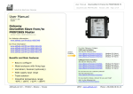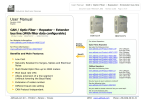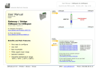
1
User Manual
CANopen / PROFIBUS Master
Document code: MN67426_ENG
Revision 1.000
Page 1 of 36
Industrial Electronic Devices
User Manual
Revision 1.000
English
CANopen / PROFIBUS Master Converter
(Order Code: HD67426)
HD67426
for Website information:
www.adfweb.com?Product=HD67426
For others Gateways / Bridges:
for Price information:
www.adfweb.com?Price=HD67426
CANopen to Modbus
Benefits and Main Features:
See also the following links:
www.adfweb.com?Product=HD67001
www.adfweb.com?Product=HD67502
www.adfweb.com?Product=HD67504
www.adfweb.com?Product=HD67505
Very easy to configure
(Modbus RTU Master)
(Modbus RTU Slave)
(Modbus TCP Master)
(Modbus TCP Slave)
For others Gateways / Bridges:
For CAN bus 2.0A and/or CAN bus 2.0B to Modbus
PROFIBUS Baudrate up to 6M
See also the following links:
www.adfweb.com?Product=HD67011
www.adfweb.com?Product=HD67012
www.adfweb.com?Product=HD67514
www.adfweb.com?Product=HD67515
Wide supply input range
Do you have an your customer protocol?
Low cost
(Modbus
(Modbus
(Modbus
(Modbus
RTU Slave)
RTU Master)
TCP Slave)
TCP Master)
Isolation between two buses
See the following links:
www.adfweb.com?Product=HD67003
Industrial temperature range:
-40°C / 105°C (-40°F / 221°F)
Do you need to choose a device? do you want help?
ADFweb.com Srl – IT31010 – Mareno – Treviso
Ask it to the following link:
www.adfweb.com?Cmd=helpme
INFO: www.adfweb.com
Phone +39.0438.30.91.31
User Manual
CANopen / PROFIBUS Master
Document code: MN67426_ENG
Revision 1.000
Page 2 of 36
Industrial Electronic Devices
INDEX:
INDEX
UPDATED DOCUMENTATION
REVISION LIST
WARNING
TRADEMARKS
SECURITY ALERT
CHARACTERISTICS
CONFIGURATION
EXAMPLES OF CONNECTION
CONNECTION SCHEME
POWER SUPPLY
PROFIBUS
CANOPEN
USE OF COMPOSITOR SW67426
NEW PROJECT / OPEN PROJECT
SET COMMUNICATION
PROFIBUS NETWORK
MASTER PROFIBUS OPTIONS
PROFIBUS DEVICE
SET SDO SERVER
SET SDO CLIENT
SET PDO ACCESS
UPDATE DEVICE
MECHANICAL DIMENSIONS
ORDER CODE
ACCESSORIES
DISCLAIMER
OTHER REGULATIONS AND STANDARDS
WARRANTIES AND TECHNICAL SUPPORT
RETURN POLICY
PRODUCTS AND RELATED DOCUMENTS
UPDATED DOCUMENTATION:
Page
2
2
2
2
2
3
4
4
5
6
8
9
10
11
11
12
13
14
15
23
24
26
28
30
34
34
35
35
36
36
36
Dear customer, we thank you for your attention and we remind you that
you need to check that the following document is:
Updated
Related to the product you own
To obtain the most recently updated document, note the “document code”
that appears at the top right-hand corner of each page of this document.
With this “Document Code” go to web page www.adfweb.com/download/
and search for the corresponding code on the page. Click on the proper
“Document Code” and download the updates.
To obtain the updated documentation for the product that you own, note
the “Document Code” (Abbreviated written "Doc. Code" on the label on
the product) and download the updated from our web site
www.adfweb.com/download/
REVISION LIST:
Revision
1.000
Date
Author
17/11/2012
Ff
Chapter
All
Description
First release version
WARNING:
ADFweb.com reserves the right to change information in this manual
about our product without warning.
ADFweb.com is not responsible for any error this manual may contain.
TRADEMARKS:
All trademarks mentioned in this document belong to their respective
owners.
ADFweb.com Srl – IT31010 – Mareno – Treviso
INFO: www.adfweb.com
Phone +39.0438.30.91.31
User Manual
CANopen / PROFIBUS Master
Document code: MN67426_ENG
Revision 1.000
Page 3 of 36
Industrial Electronic Devices
SECURITY ALERT:
GENERAL INFORMATION
To ensure safe operation, the device must be operated according to the instructions in the manual. When using the device are required for
each individual application, legal and safety regulation. The same applies also when using accessories.
INTENDED USE
Machines and systems must be designed so the faulty conditions do not lead to a dangerous situation for the operator (i.e. independent limit
switches, mechanical interlocks, etc.).
QUALIFIED PERSONNEL
The device can be used only by qualified personnel, strictly in accordance with the specifications.
Qualified personnel are persons who are familiar with the installation, assembly, commissioning and operation of this equipment and who
have appropriate qualifications for their job.
RESIDUAL RISKS
The device is state of the art and is safe. The instrument can represent a potential hazard if they are inappropriately installed and operated
by personnel untrained. These instructions refer to residual risks with the following symbol:
This symbol indicates that non-observance of the safety instructions is danger for people to serious injury or death and / or the
possibility of damage.
CE CONFORMITY
The declaration is made by us. You can send an email to [email protected] or give us a call if you need it.
ADFweb.com Srl – IT31010 – Mareno – Treviso
INFO: www.adfweb.com
Phone +39.0438.30.91.31
User Manual
CANopen / PROFIBUS Master
Document code: MN67426_ENG
Revision 1.000
Page 4 of 36
Industrial Electronic Devices
CHARACTERISTICS:
The “HD67426” series are rugged devices used to interface CANopen devices (Masters or Slaves) with PROFIBUS Slaves.
With his particular enclosure, equipped with four fixing lugs, makes available the mounting of the device in any plane surface (horizontal,
vertical, oblique).
It is possible to have the device varnished or totally resined and also in both cases with “Mini-Fit®” connectors or “AMP SuperSeal 1.5”
connectors. If is resined, the enclosure, like the “AMP SuperSeal 1.5" connectors, is waterproof (IP67).
All the four series have these characteristics:
Triple 4kV isolation between Power Supply / PROFIBUS / CANopen;
Varnished / Resined (optionally);
Wide power supply input range: 8…26V AC | 10…40V DC;
Mini-Fit® / AMP SuperSeal 1.5 connectors;
Metal enclosure with fixing lugs;
Possibility to use Metal hose clamps for fixing it without using lugs;
Microprocessor for data control;
Wide temperature range: -40°C / 105°C (-40°F / 221°F).
CONFIGURATION:
You need Compositor SW67426 software on your PC in order to perform the following:
Define the parameter of the PROFIBUS;
Define the parameter of the CANopen line;
Define the PROFIBUS network;
Define which CANopen frames contains PROFIBUS information;
Define which PROFIBUS data saves on CANopen frames.
ADFweb.com Srl – IT31010 – Mareno – Treviso
INFO: www.adfweb.com
Phone +39.0438.30.91.31
User Manual
CANopen / PROFIBUS Master
Document code: MN67426_ENG
Revision 1.000
Page 5 of 36
Industrial Electronic Devices
EXAMPLE OF CONNECTION:
ADFweb.com Srl – IT31010 – Mareno – Treviso
INFO: www.adfweb.com
Phone +39.0438.30.91.31
User Manual
CANopen / PROFIBUS Master
Document code: MN67426_ENG
Revision 1.000
Page 6 of 36
Industrial Electronic Devices
CONNECTION SCHEME:
Connector3:
CANopen port
Lo
Shl1
Hi = High wire
Hi
Lo = Low wire
Shl1 = Shield (to Isolated Ground)
Connector2:
PROFIBUS port
+
-
+ = High wire
Shl
- = Low wire
Shl = Shield (to Isolated Ground)
Connector1:
Power Supply port
0V +V
0V = Ground
+V = Positive wire
V AC: min 8V ; max 26V
V DC: min 10V ; max 40V
Figure 1-1: Connection scheme for HD67426-E4x-xxx
ADFweb.com Srl – IT31010 – Mareno – Treviso
INFO: www.adfweb.com
Phone +39.0438.30.91.31
User Manual
CANopen / PROFIBUS Master
Document code: MN67426_ENG
Revision 1.000
Page 7 of 36
Industrial Electronic Devices
Figure 1-2: Connection scheme for HD67426-E7x-xxx
ADFweb.com Srl – IT31010 – Mareno – Treviso
INFO: www.adfweb.com
Phone +39.0438.30.91.31
User Manual
CANopen / PROFIBUS Master
Document code: MN67426_ENG
Revision 1.000
Page 8 of 36
Industrial Electronic Devices
POWER SUPPLY:
The devices can be powered between a wide range of tensions. For more details see the
two tables below.
VDC
VAC
Vmin
Vmax
Vmin
Vmax
8V
26V
10V
40V
HD67426-Exx-xxx
Connector1:
Power Supply port
+V 0V
0V = Ground
+V = Positive wire
V AC: min 8V ; max 26V
V DC: min 10V ; max 40V
Consumption at 24V DC:
Device
W/VA
HD67426-Exx-xxx
4
Connector1:
Power Supply port
Caution: Not reverse the polarity power
0V
0V = Ground
+V = Positive wire
+V
V AC: min 8V ; max 26V
V DC: min 10V ; max 40V
HD67426-E4x-xxx
HD67426-E7x-xxx
Note: It is possible to use also negative tensions. In this case the polarity must be
inverted.
ADFweb.com Srl – IT31010 – Mareno – Treviso
INFO: www.adfweb.com
Phone +39.0438.30.91.31
User Manual
CANopen / PROFIBUS Master
Document code: MN67426_ENG
Revision 1.000
Page 9 of 36
Industrial Electronic Devices
PROFIBUS:
The PROFIBUS uses 3way MiniFit Maleale connector (HD67426-E4x-xx) or
AMP SuperSeal 1.5 Female connector (HD67426-E7x-xx). The pin assignment
is defined like in the right figure.
Connector2:
PROFIBUS port
Shl -
+
+ = High wire
- = Low wire
Shl = Shield (to Isolated Ground)
Connector2:
PROFIBUS port
Shl -
+
+ = High wire
- = Low wire
Shl = Shield (to Isolated Ground)
ADFweb.com Srl – IT31010 – Mareno – Treviso
INFO: www.adfweb.com
Phone +39.0438.30.91.31
User Manual
CANopen / PROFIBUS Master
Document code: MN67426_ENG
Revision 1.000
Page 10 of 36
Industrial Electronic Devices
CANOPEN:
The connection of CANopen in the HD67426-E4x-xxx device must be made with a 3way MiniFit
Female connector. The pinout of Male Mini-Fit connector of the board is at right side of the
page.
The connection of CANopen in the HD67426-E7x-xxx device must be made with a AMP
SuperSeal 1.5 Male connector. The pinout of Female connector of the board is at right side of
the page.
Connector3:
CANopen port
Hi Shl1 Lo
Hi = High wire
Lo = Low wire
Shl1 = Shield (to Isolated Ground)
The termination of CANopen line, with a 120Ω resistor, in the HD67426-Exx-xxx is made
internally of the device; when the order is performed. If the device have the CANopen
terminated the code is the follow: HD67426-Exx-Yx; otherwise is this other: HD67426-Exx-Nx.
Connector3:
CANopen port
Cable characteristics:
DC parameter:
Impedance
AC parameters:
Impedance
Delay
120 Ohm/m
5 ns/m
Length
Baud Rate [bps]
10 K
20 K
50 K
100 K
125 K
250 K
500 K
800 K
1000 K
Length MAX [m]
5000
2500
1000
650
500
250
100
50
25
ADFweb.com Srl – IT31010 – Mareno – Treviso
70
Ohm/m
Hi Shl1 Lo
Hi = High wire
Lo = Low wire
Shl1 = Shield (to Isolated Ground)
INFO: www.adfweb.com
Phone +39.0438.30.91.31
User Manual
CANopen / PROFIBUS Master
Document code: MN67426_ENG
Revision 1.000
Page 11 of 36
Industrial Electronic Devices
USE OF COMPOSITOR SW67426:
To configure the Gateway, use the available software that runs with
Windows, called SW67426. It is downloadable on the site
www.adfweb.com and its operation is described in this document.
(This manual is referenced to the last version of the software present
on our web site). The software works with MSWindows (MS 2000, XP,
Vista, Seven, 8).
When launching the SW67426 the right window appears (Fig. 2).
Note:
It is necessary to have installed .Net Framework 4.
Figure 2: Main window for SW67426
NEW PROJECT / OPEN PROJECT:
The “New Project” button creates the folder which contains the entire device configuration.
A device configuration can also be imported or exported:
To clone the configurations of a Programmable “CANopen / PROFIBUS Master - Converter” in
order to configure another device in the same manner, it is necessary to maintain the folder
and all its contents;
To clone a project in order to obtain a different version of the project, it is sufficient to
duplicate the project folder with another name and open the new folder with the button
“Open Project”.
ADFweb.com Srl – IT31010 – Mareno – Treviso
INFO: www.adfweb.com
Phone +39.0438.30.91.31
User Manual
CANopen / PROFIBUS Master
Document code: MN67426_ENG
Revision 1.000
Page 12 of 36
Industrial Electronic Devices
SET COMMUNICATION:
This section defines the fundamental communication parameter of two buses, PROFIBUS and CANopen.
By pressing the “Set Communication” button from the main window for SW67426 (Fig. 2) the window
“Set Communication” appears (Fig. 3).
The window is divided in three sections, one for the PROFIBUS , one for CANopen and the other for the
Ethernet (used for the programming).
The means of the fields for “PROFIBUS” are:
In the field “ID Dev.” the address of the PROFIBUS side is defined;
In the field “Baudrate” the baud rate for the PROFIBUS side is defined;
The means of the fields for “CANopen” are:
In the field “Device ID” the address for the CANopen side is defined;
In the field “Baudrate” the baudrate for the CANopen is defined;
In the field “Set Operational State at Start-up” the state of the CANopen is defined. I.e. if it is
checked the board starts in Operational State, else it starts in Preoperational;
In the field “Network Start at Start-up” the state of the network CANopen is defined. I.e. if it is
checked the board sends a command to set the Operational State of all the devices present in the
network;
In the field “Delay” the delay before sending the network command for the CANopen is defined;
If the field “TimeOut SDO (1/10 ms)” insert a time. It is the maximum time that the device
attends for the answer from the Slave interrogated;
Figure 3: “Set Communication” window
The means of the fields for “Ethernet (Program Port)” are:
In the “IP ADDRESS” field insert the IP Address that you want to assign to the device;
In the “SUBNET Mask” field insert the Subnet Mask of the network where the device is put.
ADFweb.com Srl – IT31010 – Mareno – Treviso
INFO: www.adfweb.com
Phone +39.0438.30.91.31
User Manual
CANopen / PROFIBUS Master
Document code: MN67426_ENG
Revision 1.000
Page 13 of 36
Industrial Electronic Devices
PROFIBUS NETWORK:
By pressing the “PROFIBUS Network” button from the main
appears.
window for SW67426 (Fig. 2) the window “PROFIBUS Network” (Fig. 4)
In this window is possible to:
Modify the PROFIBUS Master Options (“Master PROFIBUS
Options”);
Add a PROFIBUS Slave in the Network of the Master (“Add Slave
PROFIBUS”);
Modify a PROFIBUS Slave in the Network (“Modify Slave
PROFIBUS”);
Remove a PROFIBUS Slave from the Network (“Remove Slave
PROFIBUS”);
Select the SDO server for the PROFIBUS Slaves (“SDO Server”);
Select the SDO client for the PROFIBUS Slaves (“SDO Client”);
Select the PDO for the PROFIBUS Slaves (“PDO Access”);
Figure 4: “PROFIBUS Network” window
ADFweb.com Srl – IT31010 – Mareno – Treviso
INFO: www.adfweb.com
Phone +39.0438.30.91.31
User Manual
CANopen / PROFIBUS Master
Document code: MN67426_ENG
Revision 1.000
Page 14 of 36
Industrial Electronic Devices
MASTER PROFIBUS OPTIONS:
By pressin the “Master PROFIBUS Options” button from the “PROFIBUS Network” window (Fig. 4) the “PROFIBUS Master Options”
window appears (Fig. 5).
In this window is possible to set the WatchDog Time for the PROFIBUS Slaves.
Figure 5: “PROFIBUS Master Options” window
Note:
Fact1 and Fact2 could be write in decimal o hexadecimal (with prefix “0x” or “$”) and the values must between 1 and 255
Warning:
The WatchDog time must be between 200 and 650250 milliseconds.
ADFweb.com Srl – IT31010 – Mareno – Treviso
INFO: www.adfweb.com
Phone +39.0438.30.91.31
User Manual
CANopen / PROFIBUS Master
Document code: MN67426_ENG
Revision 1.000
Page 15 of 36
Industrial Electronic Devices
PROFIBUS DEVICE:
By pressing the “Add Slave PROFIBUS” and “Modify Slave PROFIBUS” button (or double click above an existent PROFIBUS Slave) from
the “PROFIBUS Network” window (Fig. 4) the “PROFIBUS Device” window appears (Fig. 6).
In this window is possible to:
Set the PROFIBUS Slave ID (“ID Slave PROFIBUS”);
Select the Modules present in the PROFIBUS Slave from the Available Modules in GSD file (“Module Selection”);
Modify the User Parameters (if present) of the PROFIBUS device (“User Parameters”);
Modify the Parameters (if present) of the Module Selected (“Module Parameters”);
Watch Features and Baudrate supported from the PROFIBUS device (“Capabilities”);
Select the Sync, Freeze and Reset of Data Options (“Options”).
Figure 6: “PROFIBUS Device” window
ADFweb.com Srl – IT31010 – Mareno – Treviso
INFO: www.adfweb.com
Phone +39.0438.30.91.31
User Manual
CANopen / PROFIBUS Master
Document code: MN67426_ENG
Revision 1.000
Page 16 of 36
Industrial Electronic Devices
MODULE SELECTION:
The section “Module Selection” is used to select which Modules are present in the Slave (Fig. 7).
In this section is possible to:
Check the list of the Modules selected (“Select Modules”) (Fig.
7, point (1)) and the list of Modules Available in GSD file
(“Available Modules") (Fig. 7, point (7));
Add a Module from the list of GSD file (Fig. 7, point (6));
Remove a Module from selected list (Fig. 7, point (5));
Add all Modules present in the GSD file (Fig. 7, point (4));
Remove all Modules from selected list (Fig. 7, point (3));
Insert a Module not present in the GSD file (“Manual
Module”) (Fig. 7 point (2)). For more info see the section
“Manual Module” below;
Enable the read of configuration directly from the PROFIBUS
Slave (“Use module configuration readed from device”)
(Fig 7, point (8)). If this option is enable the configuration of
the modules is discorded and the device read the correct
configuration directly to the PROFIBUS slave.
Figure 7: “PROFIBUS Device – Module Selection” window
ADFweb.com Srl – IT31010 – Mareno – Treviso
INFO: www.adfweb.com
Phone +39.0438.30.91.31
User Manual
CANopen / PROFIBUS Master
Document code: MN67426_ENG
Revision 1.000
Page 17 of 36
Industrial Electronic Devices
By pressing the “Manual Module” button from the “PROFIBUS Device” window (Fig. 6) the “Add Module Manually” window appears (Fig. 8).
In this window is possible to add a Module manually, i.e. writing the configuration of the module (in hexadecimal).
The means of the fields are:
In the field “Description of Module” a name of the
Module is defined;
In the field “Insert the Configuration of Module
(HEX)” the configuration of the module is defined. The
configuration must be write in hexadecimal mode (without
prefix “0x” o “$”).
To modify a Module inserted manually, is neccessary to do a
double click on the module to change in the “Select Module” list
(Fig. 7, point (1)). It is possible to change only the module
inserted manually.
Note:
The Values inserted in the table must between 00 and FF.
Figure 8: “Add/Modify Module Manually” window
ADFweb.com Srl – IT31010 – Mareno – Treviso
INFO: www.adfweb.com
Phone +39.0438.30.91.31
User Manual
CANopen / PROFIBUS Master
Document code: MN67426_ENG
Revision 1.000
Page 18 of 36
Industrial Electronic Devices
USER PARAMETERS:
The section “User Parameters” is used to modify the parameters of the PROFIBUS slave (Fig. 9).
In this section there are:
The List of all Parameters available for the
PROFIBUS device (“User Parameters”) (Fig. 9,
point (1));
The Configuration of all parameters in RAW
(“Parameters in RAW (Hex)”) (Fig. 9, point(2));
The “Use Parameter Inserted Manually”,
enable this option is possible to insert manually
the parameters of Device and also of the
Modules. Using the “Modify User Parameters
Manually” button is possible to insert/modify
the parametrization of the device (and/or
modules). For more info see below. (Fig. 9,
point(3));
The admited value for the selected parameter. It
is possible to select the value desired and
confirm it with the “Apply” button. If no value
appears in this table, the “Min Value” and “Max
Value” are the limit of the parameter. (Fig. 9,
point(4));
The “Apply” button is used to confirm the new
value of the parameter, the “Default” button is
used to load the factory value for the parameter.
In “New Value” edit box it is possible to set the
new value. (Fig. 9, point(5)).
Figure 9: “PROFIBUS Device – User Parameters” window
ADFweb.com Srl – IT31010 – Mareno – Treviso
INFO: www.adfweb.com
Phone +39.0438.30.91.31
User Manual
CANopen / PROFIBUS Master
Document code: MN67426_ENG
Revision 1.000
Page 19 of 36
Industrial Electronic Devices
By pressing the “Modify User Parameters Manually” button from the “PROFIBUS Device” window (Fig. 6) the “Add Module Manually”
window appears (Fig. 10).
In this window is possible to add/modify the User and/or Modules Parameters manually, i.e. writing the configuration of the parameters (in
hexadecimal).
The means of the fields are:
In the field “Insert the number of User Parameter” the
number of byte for the parameter have to be inserted;
In the field “Insert the Configuration of Module (HEX)”
the configuration of the User and/or Modules Parameters is
defined. The configuration must be write in hexadecimal
mode (without prefix “0x” o “$”).
Note:
The Values inserted in the table must between 00 and FF
Figure 10: “Add/Modify User Parameters Manually” window
ADFweb.com Srl – IT31010 – Mareno – Treviso
INFO: www.adfweb.com
Phone +39.0438.30.91.31
User Manual
CANopen / PROFIBUS Master
Document code: MN67426_ENG
Revision 1.000
Page 20 of 36
Industrial Electronic Devices
MODULE PARAMETERS:
The section “Module Parameters” is used to modify the parameters of the Modules (Fig. 11).
In this section there are:
The List of all Module selected in the GSD file
(“Available modules”) (Fig. 11, point (1));
The List of all Parameters available for the Module
selected (“Parameters of module”) (Fig. 11, point
(2));
The Configuration of all parameters in RAW for the
Module selected (“Parameters in RAW (Hex)”) (Fig.
11, point(3));
The admited value for the selected parameter. It is
possible to select the value desired and confirm it
with the “Apply” button. If no value appears in
this table, the “Min Value” and “Max Value” are the
limit of the parameter. (Fig. 11, point(4));
The “Apply” button is used to confirm the new
value of the parameter, the “Default” button is
used to load the factory value for the parameter.
In “New Value” edit box it is possible to set the
new value. (Fig. 11, point(5));
Figure 11: “PROFIBUS Device – Module Parameters” window
ADFweb.com Srl – IT31010 – Mareno – Treviso
INFO: www.adfweb.com
Phone +39.0438.30.91.31
User Manual
CANopen / PROFIBUS Master
Document code: MN67426_ENG
Revision 1.000
Page 21 of 36
Industrial Electronic Devices
CAPABILITIES:
The section “Capabilities” is used only to show which features/baudrates available in the PROFIBUS device. The Green Icon indicate that
capability/baudrate is available, the Red Icon indicate no compatibilities with that capability/baudrate (Fig. 12).
Figure 12: “PROFIBUS Device – Capabilities” window
ADFweb.com Srl – IT31010 – Mareno – Treviso
INFO: www.adfweb.com
Phone +39.0438.30.91.31
User Manual
CANopen / PROFIBUS Master
Document code: MN67426_ENG
Revision 1.000
Page 22 of 36
Industrial Electronic Devices
OPTIONS:
The section “Options” is used to enable some option for each PROFIBUS device (Fig. 13).
The means of the fields are:
In the field “Enable Sync” the PROFIBUS
Sync command is enable. This option is
enable only if the “Sync Mode” is
supported by the device (see Capabilities
section to check it);
In the field “Enable Freeze” the
PROFIBUS Freeze command is enable.
This option is enable only if the “Freeze
Mode” is supported by the device (see
Capabilities section to check it);
In the field “Reset data if PROFIBUS
master loses communication from
the slave” is possible to select to cancel
the data of the slave if the Master lost
the connection with the device.
Figure 13: “PROFIBUS Device – Options” window
ADFweb.com Srl – IT31010 – Mareno – Treviso
INFO: www.adfweb.com
Phone +39.0438.30.91.31
User Manual
CANopen / PROFIBUS Master
Document code: MN67426_ENG
Revision 1.000
Page 23 of 36
Industrial Electronic Devices
SET SDO SERVER:
By pressing the “Set SDO Server” button from
the main window for SW67426 (Fig. 4) the
window “Set SDO Server Access” appears (Fig.
4).
This window is made to create the SDO in read
or write in the CANopen side, and to indicate
which byte are associated to these SDOs.
It is divided in two parts, the “SDO in read” and
Figure 14: “Set SDO Server Access” window
the “SDO in Write”.
The first parte is used to read, using the SDO, the data arrived from the PROFIBUS slaves.
The second is used to write, using SDO, the data that will be sent to the PROFIBUS slaves.
The data of the columns have the following meanings:
In the field “Index” the address of the SDO is defined;
In the field “SubIndex” the second
address of the SDO is defined;
If the field “N Byte” the dimension of the SDO is defined (it can be 1, 2 or 4);
If the field “PROFIBUS ID” insert the address of the PROFIBUS Slave where to read/write data;
In the field “Address Byte1” insert the address of the PROFIBUS arrays where read/write first byte of the SDO;
In the field “Address Byte2” insert the address of the PROFIBUS arrays where read/write second byte of the SDO (only if N Byte is
2 or 4);
In the field “Address Byte3” insert the address of the PROFIBUS arrays where read/write third byte of the SDO (only if N Byte is
4);
In the field “Address Byte4” insert the address of the PROFIBUS arrays where read/write fourth byte of the SDO (only if N Byte is
4);
In the field “Mnemonic” the description for the SDO is defined.
It is possible to configure a maximum of 1000 SDOs (500 in read and 500 in write) in the “Set SDO Server Access” section.
ADFweb.com Srl – IT31010 – Mareno – Treviso
INFO: www.adfweb.com
Phone +39.0438.30.91.31
User Manual
CANopen / PROFIBUS Master
Document code: MN67426_ENG
Revision 1.000
Page 24 of 36
Industrial Electronic Devices
SET SDO CLIENT:
By pressing the “Set SDO Client” button from the main window for SW67426 (Fig. 4) the window “Set SDO Client Access” appears (Fig.
15A and 15B).
With the SDO Client the HD67426 converter can read and/or write the data from other devices connected in the network CANopen.
It is divided in two parts, the " SDO Read" and the "SDO Write". The first part is used to read, using the SDO, the data in another device and
then put this data in the PROFIBUS Slave. The second part is used to write, using the SDO, the data present in the PROFIBUS Slave to other
CANopen devices.
The data of the columns in the “SDO Read” have the following meanings:
In the field "Device ID" insert the ID of the
device used to read the data;
In the field "Index" the address for the SDO
is defined;
In the field "SubIndex" the second address
for the SDO is defined;
In the field "N Byte" the dimension of the
SDO is defined (it can be 1, 2, or 4);
In the field “Poll Time” insert the time to
make this request;
Figure 15A: “Set SDO Client Access – SDO Read” window
If the field “PROFIBUS ID” insert the address of the PROFIBUS Slave where to write data;
In the field “Address Byte1” the address of the PROFIBUS array where to copy the first byte of the SDO read is defined;
In the field “Address Byte2” the address of the PROFIBUS array where to copy the second byte of the SDO read is defined (only if
N Byte is 2 or 4);
In the field “Address Byte3” the address of the PROFIBUS array where to copy the third byte of the SDO read is defined (only if N
Byte is 4);
In the field “Address Byte4” the address of the PROFIBUS array where to copy the fourth byte of the SDO read is defined (only if N
Byte is 4);
In the field “Mnemonic” the description for the SDO is defined.
It is possible to configure a maximum of 256 read SDOs in the “Set SDO Client Access – SDO Read” section.
ADFweb.com Srl – IT31010 – Mareno – Treviso
INFO: www.adfweb.com
Phone +39.0438.30.91.31
User Manual
CANopen / PROFIBUS Master
Document code: MN67426_ENG
Revision 1.000
Page 25 of 36
Industrial Electronic Devices
The data of the columns in the “SDO Write” have the following meanings:
In the field "Device ID" insert the ID of the
device used to write the data;
In the field "Index" the address for the SDO
is defined;
In the field "SubIndex" the second address
for the SDO is defined;
In the field "N Byte" the dimension of the
SDO is defined (it can be 1, 2, or 4);
In the field “Poll Time” insert the time to
make this request;
Figure 15B: “Set SDO Client Access – SDO Write” window
If the field “On Change” is checked, the gateway send the Write SDO request when the data change the value;
If the field “PROFIBUS ID” insert the address of the PROFIBUS Slave where to read data;
In the field “Address Byte1” the address of the PROFIBUS array where to read the first byte of the SDO write is defined;
In the field “Address Byte2” the address of the PROFIBUS array where to read the second byte of the SDO write is defined (only if
N Byte is 2 or 4);
In the field “Address Byte3” the address of the PROFIBUS array where to read the third byte of the SDO write is defined (only if N
Byte is 4);
In the field “Address Byte4” the address of the PROFIBUS array where to read the fourth byte of the SDO write is defined (only if N
Byte is 4);
In the field “Mnemonic” the description for the SDO is defined.
It is possible to configure a maximum of 256 write SDOs in the “Set SDO Client Access – SDO Write” section.
ADFweb.com Srl – IT31010 – Mareno – Treviso
INFO: www.adfweb.com
Phone +39.0438.30.91.31
User Manual
CANopen / PROFIBUS Master
Document code: MN67426_ENG
Revision 1.000
Page 26 of 36
Industrial Electronic Devices
SET PDO ACCESS:
By pressing the “Set PDO Access” button from the main window for SW67426 (Fig. 4) the window “Set PDO Access” appears (Fig. 16A
and 16B).
This window is made to create the Receive and Transmit PDOs in CANopen side, and to indicate which bytes are associated to these PDOs.
It is divided in two parts, the "Receive PDO" and the "Transmit PDO". The first part is used to Receive PDO in the CANopen network and copy
the data in the PROFIBUS devices. The second part is used to Transmit PDO in the CANopen network with the data of PROFIBUS devices.
The data of the columns in the “Receive PDO” have the following meanings:
In the Field "Cob-ID" the address for the PDO
is defined;
In the Field "Dimension" the dimension of the
PDO is defined (it can be between 1 and 8);
If the field “PROFIBUS ID” insert the address
of the PROFIBUS Slave where to write data;
In the Field "Add B1" the first byte where the
data will be saved in the PROFIBUS array is
defined;
Figure 16A: “Set PDO Access – Receive PDO” window
In the Field "Add B2" the second byte where the data will be saved in the PROFIBUS array is defined (only if Dimension > 1);
In the Field "Add B3" the third byte where the data will be saved in the PROFIBUS array is defined (only if Dimension > 2);
In the Field "Add B4" the fourth byte where the data will be saved in the PROFIBUS array is defined (only if Dimension > 3);
In the Field "Add B5" the fifth byte where the data will be saved in the PROFIBUS array is defined (only if Dimension > 4);
In the Field "Add B6" the sixth byte where the data will be saved in the PROFIBUS array is defined (only if Dimension > 5);
In the Field "Add B7" the seventh byte where the data will be saved in the PROFIBUS array is defined (only if Dimension > 6);
In the Field "Add B8" the eighth byte where the data will be saved in the PROFIBUS array is defined (only if Dimension > 7);
The field “TimeOut” is used for put at zero the data into PROFIBUS if the PDO doesn’t arrive with a frequency less than the time
expressed in the field. If the value in the field is 0, means that you don’t want to use this feature, and so the value is never deleted;
In the field "Mnemonic" the description for the PDO is defined.
It is possible to configure a maximum of 30 Receive PDO in the “Set PDO Access – Receive PDO”
ADFweb.com Srl – IT31010 – Mareno – Treviso
INFO: www.adfweb.com
Phone +39.0438.30.91.31
User Manual
CANopen / PROFIBUS Master
Document code: MN67426_ENG
Revision 1.000
Page 27 of 36
Industrial Electronic Devices
The data of the columns in the “Transmit PDO” have the following meanings:
In the Field "Cob-ID" the address for the PDO is
defined;
In the Field "Dimension" the dimension of the
PDO is defined (it can be between 1 and 8);
If the field “PROFIBUS ID” insert the address of
the PROFIBUS Slave where to read data;
In the Field "Add B1" the first byte where the
data will be loaded in the EtherNet/IP array is
defined;
Figure 16B: “Set PDO Access – Transmit PDO” window
In the Field "Add B2" the second byte where the data will be loaded in the EtherNet/IP array is defined (only if Dimension > 1);
In the Field "Add B3" the third byte where the data will be loaded in the EtherNet/IP array is defined (only if Dimension > 2);
In the Field "Add B4" the fourth byte where the data will be loaded in the EtherNet/IP array is defined (only if Dimension > 3);
In the Field "Add B5" the fifth byte where the data will be loaded in the EtherNet/IP array is defined (only if Dimension > 4);
In the Field "Add B6" the sixth byte where the data will be loaded in the EtherNet/IP array is defined (only if Dimension > 5);
In the Field "Add B7" the seventh byte where the data will be loaded in the EtherNet/IP array is defined (only if Dimension > 6);
In the Field "Add B8" the eighth byte where the data will be loaded in the EtherNet/IP array is defined (only if Dimension > 7);
In the Field “Send Time ” insert the interval used to send the PDO. The time is in milliseconds;
If the field “On Change” is checked, the gateway send the Transmit PDO when the data change the value;
In the field "Mnemonic" the description for the PDO is defined.
It is possible to configure a maximum of 30 Transmit PDO in the “Set PDO Access – Transmit PDO”
ADFweb.com Srl – IT31010 – Mareno – Treviso
INFO: www.adfweb.com
Phone +39.0438.30.91.31
User Manual
CANopen / PROFIBUS Master
Document code: MN67426_ENG
Revision 1.000
Page 28 of 36
Industrial Electronic Devices
UPDATE DEVICE:
By pressing the “Update Device” button it is possible to load the created Configuration into the device; and also the Firmware, if is
necessary.
In order to load the parameters or update the firmware in the Converter, follow these instructions:
Connect the AC67400 to the PC;
Connect the CAN port of AC67400 to CANopen port of HD67426;
Feed the HD67426;
Turn on the device;
Select the “COM port” and press the “Connect” button;
Press the “Next” button;
Select which operations you want to do.
Press the “Execute update firmware” button to start the upload;
When all the operations are “OK” turn off the device;
Disconnect the AC67400;
Turn on the device.
At this point the configuration/firmware on the device is correctly update.
Figure 10: “Update Device” windows
ADFweb.com Srl – IT31010 – Mareno – Treviso
INFO: www.adfweb.com
Phone +39.0438.30.91.31
User Manual
CANopen / PROFIBUS Master
Document code: MN67426_ENG
Revision 1.000
Page 29 of 36
Industrial Electronic Devices
Note:
When you install a new version of the software it is better if the first time you do the update of the Firmware in the HD67426 device.
Note:
When you receive the device, for the first time, you have to update also the Firmware in the HD67426 device.
Warning:
If the Fig. 9 appears when you try to do the Update before require assistance try these points:
Check if the serial COM port selected is the correct one;
Check if the AC67400 is connected between the PC and the device;
Try to repeat the operations for the updating;
If you are using a dongle try with a native COM port or change the dongle;
Try with another PC;
Try to restart the PC;
If you are using the program inside a Virtual Machine, try to use in the main
Operating System;
If you are using Windows Seven or Vista or 8, make sure that you have the
administrator privileges;
Figure 11: “Protection” window
Take attention at Firewall lock.
ADFweb.com Srl – IT31010 – Mareno – Treviso
INFO: www.adfweb.com
Phone +39.0438.30.91.31
User Manual
CANopen / PROFIBUS Master
Document code: MN67426_ENG
Revision 1.000
Page 30 of 36
Industrial Electronic Devices
MECHANICAL DIMENSIONS:
ADFweb.com Srl – IT31010 – Mareno – Treviso
INFO: www.adfweb.com
Phone +39.0438.30.91.31
User Manual
CANopen / PROFIBUS Master
Document code: MN67426_ENG
Revision 1.000
Page 31 of 36
Industrial Electronic Devices
Type A
ADFweb.com Srl – IT31010 – Mareno – Treviso
INFO: www.adfweb.com
Phone +39.0438.30.91.31
User Manual
CANopen / PROFIBUS Master
Document code: MN67426_ENG
Revision 1.000
Page 32 of 36
Industrial Electronic Devices
Type B
ADFweb.com Srl – IT31010 – Mareno – Treviso
INFO: www.adfweb.com
Phone +39.0438.30.91.31
User Manual
CANopen / PROFIBUS Master
Document code: MN67426_ENG
Revision 1.000
Page 33 of 36
Industrial Electronic Devices
Type C
ADFweb.com Srl – IT31010 – Mareno – Treviso
INFO: www.adfweb.com
Phone +39.0438.30.91.31
User Manual
CANopen / PROFIBUS Master
Document code: MN67426_ENG
Revision 1.000
Page 34 of 36
Industrial Electronic Devices
ORDERING INFORMATIONS:
The ordering part number is formed by a valid combination of the following:
HD67426 – E y z – s f
Fixing lugs
A: Type 1
B: Type 2
C: Type 3
CANopen Termination
Y: Terminated with 120Ω
N: Not terminated
Varnished/Resinated
V: Varnished
R: Resined
Connectors Type
4: MiniFit
7: SuperSeal 1.5
Enclosure Type
E: Metal enclosure
Device Family
HD67426 = CANopen / PROFIBUS Master - Converter
ACCESSORIES:
Order Code: AC67400
-
CAN interface to configure devices
ADFweb.com Srl – IT31010 – Mareno – Treviso
INFO: www.adfweb.com
Phone +39.0438.30.91.31
User Manual
CANopen / PROFIBUS Master
Document code: MN67426_ENG
Revision 1.000
Page 35 of 36
Industrial Electronic Devices
DISCLAIMER
All technical content within this document can be modified without notice. The content of the document content is a recurring audit.
For losses due to fire, earthquake, third party access or other accidents, or intentional or accidental abuse, misuse, or use under abnormal
conditions repairs are charged to the user. ADFweb.com S.r.l. will not be liable for accidental loss of use or inability to use this product, such
as loss of business income. ADFweb.com S.r.l. shall not be liable for consequences of improper use.
OTHER REGULATIONS AND STANDARDS
WEEE INFORMATION
Disposal of old electrical and electronic equipment (as in the European Union and other European countries with separate
collection systems).
This symbol on the product or on its packaging indicates that this product may not be treated as household rubbish. Instead, it
should be taken to an applicable collection point for the recycling of electrical and electronic equipment. If the product is disposed
correctly, you will help prevent potential negative environmental factors and human health, which could otherwise be caused by
inappropriate disposal. The recycling of materials will help to conserve natural resources. For more information about recycling this
product, please contact your local city office, your household waste disposal service or the shop where you purchased the product.
RESTRICTION OF HAZARDOUS SUBSTANCES DIRECTIVE
The device respects the 2002/95/EC Directive on the restriction of the use of certain hazardous substances in electrical
and electronic equipment (commonly referred to as Restriction of Hazardous Substances Directive or RoHS).
CE MARKING
The product conforms with the essential requirements of the applicable EC directives.
ADFweb.com Srl – IT31010 – Mareno – Treviso
INFO: www.adfweb.com
Phone +39.0438.30.91.31
User Manual
CANopen / PROFIBUS Master
Document code: MN67426_ENG
Revision 1.000
Page 36 of 36
Industrial Electronic Devices
WARRANTIES AND TECHNICAL SUPPORT:
For fast and easy technical support for your ADFweb.com SRL products, consult our internet support at www.adfweb.com.
Otherwise contact us at the address [email protected]
RETURN POLICY:
If while using your product you have any problem and you wish to exchange or repair it, please do the following:
1) Obtain a Product Return Number (PRN) from our internet support at www.adfweb.com. Together with the request, you need to
provide detailed information about the problem.
2) Send the product to the address provided with the PRN, having prepaid the shipping costs (shipment costs billed to us will not be
accepted).
If the product is within the warranty of twelve months, it will be repaired or exchanged and returned within three weeks. If the product is no
longer under warranty, you will receive a repair estimate.
PRODUCTS AND RELATED DOCUMENTS:
Part
Description
URL
HD67121
Gateway CANopen / Canopen
www.adfweb.com?product=HD67121
HD67502
Gateway CANopen / Modbus - RTU
www.adfweb.com?product=HD67502
HD67505
Gateway CANopen / Modbus – Ethernet TCP
www.adfweb.com?product=HD67505
HD67134
Gateway CANopen / DeviceNet
www.adfweb.com?product=HD67134
HD67117
CAN bus Repeater
www.adfweb.com?product=HD67117
HD67216
CAN bus Analyzer
www.adfweb.com?product=HD67216
ADFweb.com Srl – IT31010 – Mareno – Treviso
INFO: www.adfweb.com
Phone +39.0438.30.91.31