1
Installation Manual
Dimmer Rack
EC21 Manual Part Number:
Revision Level:
Revision Date:
Written By:
Revised By:
2-450173-030
A0
23-September-2009
Charles Coley, II
Stanley Ray
The material in this manual is for information purposes only and is subject to
change without notice. Strand Lighting assumes no responsibility for any errors
or omissions, which may appear in this manual. For comments and
suggestions regarding corrections and/or updates to this manual, please
contact the nearest Strand Lighting office.
El contenido de este manual es solamente para información y está sujeto a
cambios sin previo aviso. Strand Lighting no asume responsabilidad por
errores o omisiones que puedan aparecer. Cualquier comentario, sugerencia o
corrección con respecto a este manual, favor de dirijirlo a la oficina de Strand
Lighting más cercana.
Der Inhalt dieses Handbuches ist nur für Informationszwecke gedacht,
Aenderungen sind vorbehalten. Strand Lighting uebernimmt keine
Verantwortung für Fehler oder Irrtuemer, die in diesem Handbuch auftreten.
Für Bemerkungen und Verbesserungsvorschlaege oder Vorschlaege in Bezug
auf Korrekturen und/oder Aktualisierungen in diesem Handbuch, moechten wir
Sie bitten, Kontakt mit der naechsten Strand Lighting-Niederlassung
aufzunehmen.
Le matériel décrit dans ce manuel est pour information seulement et est sujet
à changements sans préavis. La compagnie Strand Lighting n’assume aucune
responsibilité sur toute erreur ou ommission inscrite dans ce manuel. Pour
tous commentaires ou suggestions concernant des corrections et/ou les mises
à jour de ce manuel, veuillez s’ll vous plait contacter le bureau de Strand
Lighting le plus proche.
© 2004-2009, Philips Group. All rights reserved.
Information contained in this document may not be duplicated in full or in part
by any person without prior written approval of Strand Lighting. Its sole
purpose is to provide the user with detailed installation information for the
equipment supplied. The use of this document for all other purposes is
specifically prohibited.
Prefix
This manual describes the installation procedures for EC21 dimmer racks. A
separate Operator's Guide describes the software operation and its use.
Thank you for choosing Strand Lighting EC21 dimmer racks. We trust that the
equipment will meet all your dimming needs and will provide you with reliable
service for many years.
Strand Lighting can assure you that every effort has been made to ensure that
the equipment has been designed to meet the highest professional standards
and that dimmer racks and their components have been assembled,
inspected, and tested in accordance with our strict quality assurance program.
Should you encounter any problems or difficulties with your dimmer racks,
please contact the nearest Strand Lighting service representative. For a
complete list of Strand Lighting offices and service centers, see below or visit
our Web site (www.strandlighting.com).
Strand Lighting Offices:
Strand Lighting – Los Angeles,
6603 Darin Way, Cypress, CA 90630, USA
Tel: +1 714 230 8200 Fax: +1 714 230 8173
Strand Lighting – Asia,
20/F Delta House, 3 On Yiu Street, Shatin, N.T. Hong Kong
Tel: +852 2757 3033 Fax: +852 2757 1767
Strand Lighting – New York,
267 5th Avenue, 4th Floor, New York, NY 10016, USA
Tel: +1 212 213 8219 Fax: +1 212 532 2843
Strand Lighting – Auckland,
19-21 Kawana Street, Northcote, Auckland 0627, New Zealand
Tel: +64 9 481 0100 Fax: +64 9 481 0101
Strand Lighting – Dallas,
10911 Petal Street, Dallas, TX 75238, USA
Tel: +1 214 647 7880 Fax: +1 214 647 8030
Strand Lighting – European Service & Distribution Centre,
Marssteden 152, Enschede 7547 TD, The Netherlands
Tel: +31-53-4500424 Fax: +31-53-4500425
i
Table of Contents
This manual describes the installation of the EC21 dimmer rack. The installer
should refer to the separate EC21 Operators Guide for detailed information
concerning the initial setup procedures referred to in the Commissioning
section of this manual. Basic Troubleshooting is also provided in the EC21
Operator's Guide.
Definition Of Terms .............................................................................................. v
Technical Assistance .......................................................................................... vi
Section 1 - Hardware Description................................................. 1
General................................................................................................................. 1
Construction ......................................................................................................... 2
Section 2 - Installation................................................................... 7
Environmental Considerations ............................................................................. 7
Conduit Layout ..................................................................................................... 8
Positioning the Dimmer Rack(s) .......................................................................... 9
Preparing the Rack for Wiring ............................................................................10
Locating Dimmer Components ..........................................................................11
Power Wiring ......................................................................................................12
Caution.......................................................................................... 13
Load Wiring ........................................................................................................14
Control Wiring.....................................................................................................15
Connecting the Dimmer Control Cable Harness ...............................................17
Connecting the Control Signal Wiring................................................................17
Installing the Door ..............................................................................................24
Section 3 - Commissioning......................................................... 25
Safety Check ......................................................................................................25
Initial Power Up ..................................................................................................25
Processor Self Test and Fault Identification ......................................................26
LED Status .........................................................................................................27
Output Check .....................................................................................................28
Initial Programming ............................................................................................28
Programming and Fault-Finding ........................................................................28
Index................................................................................................ 2
iiTable of Contents
Figures
Figure 1 – EC21 Rack Layout Fully Populated ...........................................1
Figure 2 – Rack Processor Housing (RPH) .................................................3
Figure 3 – Rack Processor Module (RPM)..................................................4
Figure 4 – Control Interconnection Card (CIC)...........................................5
Figure 5 – Dual Dimmer Module ................................................................6
Figure 6 – Recommended Conduit Cutouts.................................................8
Figure 7 – Mounting Dimensions ................................................................9
Figure 8 – Clearances ................................................................................10
Figure 9 – EC21 Dimmer Rack .................................................................11
Figure 10 – Bus Bar Connections Behind Processor Assembly ................12
Figure 11 – Compression Fittings Detail ...................................................13
Figure 12 – EC21 Dimmer Receptacles.....................................................14
Figure 13 – EC21 Load Earth Terminals...................................................14
Figure 14 – Install Electronics Chassis......................................................15
Figure 15 – Connecting Power to the Rack Processor Housing (RPH).....16
Figure 16 – Connecting Control Signal Wiring.........................................17
Figure 17 – Ethernet Wiring and Termination...........................................18
Figure 18 – DMX512 Wiring and Termination.........................................19
Figure 19 – SWC/Outlook Wiring and Termination .................................20
Figure 20 – Remote Contact Closure Termination ....................................21
Figure 21 – A/V Interface Termination .....................................................22
Figure 22 – Installing EC21 Rack Hinge Plate and Door ..........................24
Figure 23 – Rack Processor Module Front Panel ......................................26
Tables
Table 1 – Ethernet Termination .................................................................18
Table 2 – DMX512 Termination ...............................................................19
Table 3 – SWC/Outlook Termination........................................................20
Table 4 – Remote Contact Closure Termination .......................................21
Table 5 – RS-232 A/V Interface Termination ...........................................22
iii
iv
Definition Of Terms
This manual uses the following definitions throughout:
channel
Device controlling a dimmer or group of dimmers. Historically, there is a
physical controller (such as a slider) for each channel. On most current control
systems, channels are numbers accessed by a keypad. Each channel can
control multiple dimmers.
CIC
(control interconnection card) The printed circuit board on which all contractor
low-voltage control wiring connections are made. It is located on the top of the
rack processor housing.
circuit
circuit ID
crossfade
CSA
cue
Connection device and wiring for powering a lighting fixture from a dimmer.
A unique identification string ranging from 1 to 99,999 which you assign to
each dimmer. The circuit ID is generally the same as the dimmer number.
A fade which contains both an up-fade and a down-fade. Also may refer to
any fade where the levels of one cue are replaced by the levels of another cue.
Cross Sectional Area – describes cable size, and that of connectors to
accommodate them.
The process of recalling a preset from its memory location and putting the
result on stage.
Preset, memory, and cue are often used interchangeably.
curve
dimmer
default
The relationship between a control level and the actual dimmer output.
Device controlling power to a lighting fixture. Two luminaries on the same
dimmer cannot be separately controlled.
The original factory settings.
DMX512
An ANSI communications protocol standard that describes a method of digital
data transmission between controllers, lighting equipment and accessories.
Ethernet
A high-speed network based protocol used to transmit data from a lighting
controller to a dimmer rack using a single Ethernet cable.
fade
fade time
Level
Outlook
A gradual change in stage levels from one set of intensities ("look") to another.
The time it takes for dimmer levels to go from their current levels to the levels
in the selected preset. Each preset has its own fade time.
A numerical value used to express the “brightness” of a dimmer. Usually
shown as %.
Architectural control system located within the rack processor module (RPM)
containing 16 rooms, 8 programmable presets plus on & off and 15 channels
of control per room.
patch
Historically, the process of physically connecting circuits to dimmers. Now
usually refers to electronic assignment of dimmers to channels.
phase
The three phases of the mains supply to which the dimmers are connected are
identified as Line 1, Line 2, and Line 3 in 230v markets and Phase A, Phase B,
and Phase C in 120v markets.
power module
A chassis containing one or two dimmers or contactors. This is sometimes
referred to as a “dimmer.” However, each EC21 power module can have
multiple dimmers or contactors in it, so this manual distinguishes between
dimmers (individual power control circuits) and power modules (a collection of
one or more power control circuits).
v
power cube
preset
preset fade time
rack number
room
Assembly containing one or more inverse parallel connected SCR’s together
with isolation and drive circuitry to permit control from a “logic” source.
A pre-defined set of intensities for a set of channels, stored in memory for later
replay. For Outlook applications, the EC21 processor module stores 8
programmable presets per room for up to 16 rooms. For SWC applications,
the processor module stores 128 programmable presets. Preset 0 (ZERO) is
always a blackout.
See “Fade Time.”
A number used to uniquely identify each dimmer rack in a multiple rack
system. Rack numbers are set from the front panel of the processor module,
and are usually set by the installation engineer.
An area separately defined for purposes of architectural lighting control (e.g.,
Outlook control stations). This is usually either a room in the traditional sense
(an indoor enclosed area) or a portion of a room which can be partitioned off.
Each room may be separately and simultaneously controlled by the system.
RPH
Rack Processor Housing
RPM
Rack Processor Module
SWC
(System Wide Control) A method of programming and controlling more than
one dimmer rack simultaneously. A hand held controller lets you program and
recall 128 presets, and control individual dimmers. 8 and 16 channel
pushbutton stations, and an A/V interface, let you recall any 8 or 16 of the 128
presets at each station. Please contact Strand Lighting or see the System
Wide Control Data Sheet or System Wide Control User’s Manual for details on
how SWC works.
Thyristor
Technical Assistance
Alternative term describing a silicon control rectifier.
EC21 racks and dimmers require a minimum of maintenance and servicing.
See the Operations Guide for basic troubleshooting and periodic maintenance
procedures.
For operation or technical assistance, please contact Strand Lighting or the
local Authorized Service Center serving your area. (www.strandlighting.com)
vi
Section 1 - Hardware Description
General
The EC21 dimmer rack is a listed, free standing, factory assembly of welded
steel and aluminum construction finished in a fine textured, scratch resistant
coating.
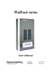
Each EC21 dimmer rack consists of a rack processor housing (RPH) with one
or two rack processor modules (RPM), a fan module, and up to 24, 36 or 48
dimmer modules. The dimmer connectors at the back of the rack provide for
load wire connection. Main bus bars are provided for line wire connections. A
earth lug is provided in the rack. The dimmer connectors in the rack are
polarized to prevent dimmer modules being plugged into slots inappropriate for
their rating. The dimmer racks can be individually fed or bused together using
an optional busing kit.
Large dimmer racks have provision for up to 48 dimmer modules. Mid-range
dimmer racks have provision for up to 36 dimmer modules. Small dimmer
racks have provisions for up to 24 dimmer modules. Dimmer modules contain
one, two or four dimmers, and dimmer module types can be mixed within a
rack in various combinations.
Rack processor modules are available with 96 or 144 dimmer control outputs
to drive EC21 dimmers.
Door Hinge
Bracket
Ventilation Grill
Dimmer Modules
Door Strike
Fan Housing
Rack Processor
Housing
Rack Processor
Module
Backup Processor
Module (Optional)
Blank Panel
Figure 1 – EC21 Rack Layout Fully Populated
Section 1 - Hardware Description
1
Construction
The rack is constructed of welded steel and aluminum with bolt-on covers, and
is finished in a fine textured, scratch resistant coating. The rack will accept
removable trays for the dimmer modules, which are screwed in place. The
rack and all modules are earth grounded. The electronics chassis and fan
module are located at the bottom of the rack.
A hinged, locking door covers the front of the dimmer rack. Rack components
are designed for easy removal and installation so that the dimmer rack is open
and empty during installation. Mounting holes are provided so that racks can
be bolted together and to the floor.
Size and Weight
Dimensions:
Weight:
Contracting Access
Supply Connection
Height 2032mm, Width 619mm, Depth 600mm
(without door, Depth with door 654mm)
With 48 dual standard dimmers and one rack processor
module - 310 Kg
Without dimmer modules, rack processor modules – 136 Kg
The mains bus bars are at the bottom of the rack. They may either be bottom
fed or the supply cables routed down the rear right hand side of the rack from
the top. Contractor load wire connections for the live and neutral route through
the top of the rack and directly onto the module connectors.
The rack is provided with three-phase plus neutral and earth bus bar
distribution, located at the bottom of the rack. The maximum power rating for
each dimmer rack is 800A per phase. Busing across multiple racks is possible
using the rack interconnection busing kit.
Note: Three-phase delta racks and single-phase racks are available in custom
applications.
Rack Supply Voltage and
Frequency
Phasing
Dimmer Module
Connectors
The EC21 rack is suitable for use with supply voltages of between 90 and
264VAC power and frequency range of 47 to 63 Hz.
Phasing within standard dimmer racks is sequential across the dimmer slots,
running in the phase sequence L1 L2, L3 L1, L2 L3. All dimmers in a vertical
column down the rack are on the same phase. In dual dimmer modules, both
dimmers are on the same phase. In quad dimmer modules, all four dimmers
are on the same phase. When looking at the front of the dimmer rack, phase
L1 is the first and fourth columns. Phase L2 is the second and fifth columns
and phase L3 is the third and sixth columns.
The modules connect to the rack through a proprietary connector with female
power pins and solid brass male power pins. The connector is self-aligning
when the module is inserted. Control signals are incorporated into the
connector.
2
The aperture is suitable for wire gauge 16mm or smaller, and has a tapered
entry hole to ease wire insertion. The wire is retained by Allen screw. A wire
2
adaptor is available for 35mm wire, when required.
Control Input/Output
Connection
Cooling Fans
The Control Interconnection Card (CIC) contains all terminals for control
input/output with the exception of the Ethernet receptacle that is located in the
upper left rear of the rack.
The dimmer racks are cooled by a set of low noise variable speed fans in a fan
module at the bottom of the rack. The cooling system is designed to let the
rack continue functioning if any one of the fans fail. Cooling air is pushed up
through the dimmer stack and exhausted through venting at the top of the
rack. These fans are for dimmer cooling only, and can be set to fixed or
variable speed.
The fixed speed fan setting is for situations where changes in ambient noise
are a problem. With this setting, the fans are always ON when any dimmer is
energized.
2
The variable speed fan setting minimizes noise and maximizes fan life. With
this setting, the fan speed with non-reporting modules is adjusted based on the
temperature of the dimmer rack. The fan speed with reporting dimmer
modules is based on the temperature of the dimmer modules and the dimmer
rack. Increases in fan speed take 1 minute with this setting, while decreases
in fan speed take 5 minutes. Fans are turned OFF when no dimmers are in
use.
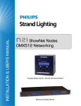
Rack Processor Housing
(RPH)
Each EC21 dimmer rack contains a rack processor housing (RPH). This
housing contains the rack processor module(s), power supplies, and control
interconnection card (CIC) for the rack, and is shipped separately from the rack
to minimize the possibility of damage.
This chassis can be equipped with one or two rack processor modules (RPM).
The second processor module acts as a backup to the main processor. The
configuration data from either processor is transferred into the other processor
automatically. The currently inactive processor always tracks the currently
active processor.
CIC
Power Supply
Plug In Connector
Main Power Supply
Optional
Power Supplies
Optional Ethernet Switch
Optional
Power Supplies
Main Power Supply
Rack Processor Housing
Optional Back-Up
Rack Processor Module
Lighthouse Beacon
CIC
Rack Processor Module
Figure 2 – Rack Processor Housing (RPH)
Section 1 - Hardware Description
3
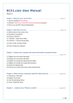
Rack Processor Module
(RPM)
Each EC21 rack contains one or two rack processor modules (RPM). The rack
processor module is available in two variations: 96 outputs and 144 outputs.
Each rack processor module has an LCD display, keypad, and LEDs to report
processor module and dimmer status and allow simple setup and control at the
rack. If there are any rack or dimmer events reported, the display will show
error messages.
Pressing the > key takes you into a series of setup menus to view and set up
the more frequently used EC21 features. See the Operator’s Manual for details
on accessing these functions.
All program data is held in non-volatile RAM within the rack processor module.
Figure 3 – Rack Processor Module (RPM)
4
Control Interconnection
Card
The Control Interconnection Card, or CIC, is the printed circuit board on which
all contractor control wiring connections are made. It is located on the top of
the Rack Processor Housing (RPH) and contains:
•
An optional Ethernet switch, which connects to a Strand ShowNet system
and is ACN (Architecture for Control Network) ready. This switch allows
for easy connections between dimmer racks. It also connects to the
network receptacle located in the upper left rear of the dimmer rack.
•
Two optically isolated DMX512 control inputs. The first input will accept
DMX512. The second DMX512 input is configurable to accept either
DMX512, Strand Lighting’s System Wide Control (SWC) dimmer protocol
or Strand Lighting’s Outlook architectural protocol. Each DMX input has a
patch to allow overlapping or separation of any DMX control level.
•
Six optically isolated contact inputs, for:
•
•
Pin
Function
Type
Description
1
2
3
4
5
6
7
8
PANIC ON
PANIC OFF
FIRE ALARM
SWC PRESET 1
GO NEXT SWC
GO SWC OFF
Com/Gnd
Com/Gnd
Momentary
Momentary
Maintained
Momentary
Momentary
Momentary
Turns Panic On
Turns Panic Off
Turns Panic On, No Override
Fires SWC Preset 1
Fires “Next” SWC Preset
Fires SWC Preset 0 (Blackout)
Com/Gnd
Com/Gnd
An Audio Visual Interface port. This serial input will support connection to
an external A/V or show control system that supports an RS232 serial
connection.
96 or 144 panic select switches
Rack Processor Module
Plug-In Connector
Fan Cable
Connector
Dimmer Control
Ribbon Connectors
(T1 – T6 & B1 – B6)
Panic Select Switches
(96 or 144 Switches)
Power Supply
Plug-In Connectors
Control Input
Connectors
Figure 4 – Control Interconnection Card (CIC)
Section 1 - Hardware Description
5
Dimmer Modules
The power modules are the high power switching section of the EC21 dimming
system. The power block in this module is the interface between the high
power AC and low power control. It is driven by low level signals (5mA, 3-24V)
and switches high level signals (up to 50A, 240VAC). High specification
filtering, thyrisor dimming, contactor non-dims, Sinewave dimming, and load
status reporting electronics are available as options. Dimmers can be mixed in
any combination in a rack. This lets you use the exact dimmer type needed for
each circuit.
Quad dimming modules are also available in custom racks.
Power modules are constructed from aluminum, folded to form three sides of
the dimmer and to support the dimmer connector and heatsink. The fourth side
of the dimmer is formed by the heatsink. The top and bottom of the dimmer are
open for cooling.
A sturdy handle is provided below the circuit breakers.
An optional locking bar on the dimmer tray secures the dimmers in the rack.
Chokes
Connector
Circuit Breakers
Dimmer Wing
With Type & Rating
Handle
Reporting PCB
(optional)
Thyristor Pack
Chassis
Figure 5 – Dual Dimmer Module
EC21 dimmer modules are available in load status reporting versions.
Reporting Dimmer Most
Load status reporting versions of dimmers can be mixed in any combination
Modules with standard dimmers in EC21 racks. These dimmers report many dimmer
status items back to the processor. The information can be accessed through
various menu items. The processor can then display a wide range of faults and
diagnostic data.
Each Reporting dimmer module contains a temperature sensor which will shut
it down if it overheats. Anything causing overheating in the rack will cause a
gradual shutdown as each Reporting dimmer module overheats.
6
Section 2 - Installation
Environmental
Considerations
Before installing your EC21 rack, you should carefully consider the
environment in which the equipment is to be installed, the power feeding the
equipment and the required conduit and/or cable runs.
To maximize equipment life and minimize the chance of failures, the following
environmental requirements should be met:
•
•
•
•
•
Warning
Operating temperature: 0 to 40°C ambient
Operating humidity: 5%-95% non-condensing
Storage temperature: -40°C to 70°C
Storage humidity: 0% to 95% non-condensing
Shock resistance in transit without damage: 40G 10mS in any of the X, Y,
Z planes.
Dimmer rack efficiency is at least 97% with standard modules. Since the
remainder of the energy is dissipated as heat, racks should be installed
in a room with adequate ventilation to dissipate a heat load equivalent to
at least 3% of the maximum load the dimmer racks will handle
Electrical equipment must not be used in close proximity to flammable
materials.
This equipment is for indoor use only
Warning
Warning
AC Lighting Loads Only!
The short circuit rating for this product is 50,000 AIC. Provisions can be
made for optional amp trap devices to provide 100,000 AIC fault current
protection, if required.
Fan and filter choke noise emissions at some levels may be
objectionable, therefore racks should be installed away from stage and
audience areas.
Do not obstruct the ventilation at the front of the dimmer rack
A 90 to 264VAC, 3-phase, 4-wire plus earth, 47 to 63Hz power source must be
provided for processor assembly power. Processor assemblies operate on
any power source in the listed range, but the power source must be correct for
the dimmers used in the system. Dimmers are available in 120V and 230VAC
models. Racks are available in three-phase, single-phase and three phase
three-wire delta configurations. Please consult Strand Lighting on the actual
main feed size required for specific installations.
Strand Lighting recommends that the dimmer rack power be a separate feed
and that no other equipment share the feed. Because phase control dimmers
rd
impose high 3 harmonics loads on the supply the supply transformer
impedance should not exceed 5%.
Dimmer racks fully populated with Sinewave modules impose no additional
harmonic loading on the supply, therefore this recommendation is inapplicable.
Do not install this equipment with power applied.
Make sure that incoming power is disconnected before proceeding with
the installation.
Section 2 - Installation
7
Conduit Layout
The location of conduit runs and their entrance to the dimmer rack is important
and should be carefully planned before cutting holes or attaching conduit.
Main Feed Wire
Entry Area
Control Wires
Entry Area
Load Wire
Entry Area
Top Of Frame
Cover Panel
Figure 6 – Recommended Conduit Cutouts
(Top of Rack)
Do not run power feed or load wires in the same conduit or wireways as
control and low voltage wiring.
Do not run load cable trays and/or conduit in close proximity to any computer
or computer equipment.
Do not run wiring from other unrelated equipment in the same conduit with
EC21 wiring.
Do not run control wires from dimmer rack locations marked for load or power
wires, and vice versa. These locations are chosen to minimize electrical
interference between various sections of the system.
Do not run wiring in ways other than shown on the system riser diagram or
use alternative control cables to those specified by Strand Lighting.
Do not substitute plastic conduit for metal conduit. Metal conduit acts as a
ground and shield.
Do not substitute shielded wiring for unshielded wiring or conduit. Changes in
transmission line capacitance can cause problems with the control signals.
8
Positioning the
Dimmer Rack(s)
Fan and choke noise may be objectionable if the racks are installed close to
audience or performance areas. The racks are best installed in a dedicated
plant room remotely located from the stage, audience, and acoustically "live"
positions of the performance area.
Attach the racks to a sturdy wall and to the floor. Mounting holes are provided
for this purpose, and are positioned as shown in Figure 7. Racks may be
placed in a "back-to back" configuration if they are attached securely to the
floor.
337.19mm
Control Wires
Entry Area
177.85mm
63.53mm
160.66mm
619.0mm
Main Feed Entry Area
Load Wires
Entry Area
101.60mm
Top Frame Leg Support
(Cut For Clarity)
Both Sides
600.0mm
Top Of Frame
Cover Panel
619.0mm
Top View
2032.0mm
1955.0mm
Rear Panel
Frame Rear Panel
Bottom Frame
Figure 7 – Mounting Dimensions
The dimmer rack must be placed on a non-combustible floor.
Note
Installing the dimmer rack on a low concrete pad (or housekeeping pad)
added on top of the floor is recommended to keep the dimmer rack clear
of incidental water or accidental flooding.
Section 2 - Installation
9
Allow adequate clearance at the front of the dimmer racks for them to be
opened for wiring purposes and safe servicing. Required clearances are
shown in Figure 8.
619.0mm
619.0mm
654.0mm
1232.66mm
Door Closed
Door Open 90º
Figure 8 – Clearances
Preparing the
Rack for Wiring
The EC21 rack is supplied without the door installed. The dimmer modules
and rack processor housing are supplied separately. In order to gain full
access to the rack, you must:
1. Remove the top and bottom grills.
2. Remove the thermostat bar.
Be careful not to damage the thermostat. A damaged or broken
thermostat will render the dimmer rack inoperable.
3. Remove the eight dimmer trays.
4. Remove the fan housing.
Do not remove the door from its carton.
Do not install the dimmer rack door.
This will be installed by a Strand Lighting Engineer or an Authorized
Service Center Technician as part of the system commissioning.
If the dimmer rack is to be installed without a factory commissioning,
then the Electrical Contractor shall install the door at the completion
of their works.
10
Locating Dimmer
Components
Hinge Bracket
Ventilation Grill
Dimmer Modules
Door Strike
Fan Housing
Rack Processor
Housing
Rack Processor
Module
Backup Processor
Module (Optional)
Blank Panel
Figure 9 – EC21 Dimmer Rack
(Door Removed for clarity)
Section 2 - Installation
11
Power Wiring
Load Wires By Installer:
Run All Load Cables
Behind Channel Supports
Power feed wiring enters the top right back of the dimmer rack only. The figure
below shows a typical top fed rack. The phase, neutral and earth power
cables enter the rack through the top. All power cables are terminated using a
suitable-rated compression lug (see Figure 11 below) and bolted to the mains
bus bars.
Power Feed By Installer
3 Phase 4 Wire + Ground,
230/480V, Top-Side Right
Entry Only
Earth Bus
Earth Lug Position.
Control Wire
By Installer
Thermostat
Route Control Wires in
Trough Down Left Side
Of Dimmer Rack
Load Terminal Blocks
L3 Incoming Linked
Bus assembly – See
Top Feed Notes
Ethernet Jack
Neutral Bus
L1 Incoming Linked
Bus assembly – See
Top Feed Notes
L2 Incoming Linked
Bus assembly – See
Top Feed Notes
Figure 10 – Bus Bar Connections Behind Processor Assembly
(Top entry shown)
12
Connect all external power feed wiring to the dimmer rack. Internal power
wiring between dimmer rack components is pre-wired at the factory.
These buss bars are rated for copper conductors only.
Caution
1.
2.
3.
Connect system ground to the earth buss bar.
Connect the neutral to the neutral bus bar.
Connect the power feeder wires to the mains bus bars.
EC21 Dimmer Rack
Bus Support
Neutral Bus Bar
Amp-Trap Installation Detail
Line Bus Link
Feed Lugs
Amp-Trap
Figure 11 – Compression Fittings Detail
Section 2 - Installation
13
Load Wiring
Load wiring is connected directly to the dimmer receptacle. Wires can be
routed down channels next to the dimmer receptacles so that they are out of
the way once the rack is assembled.
Only hook up AC lighting loads to this equipment.
Warning
Connect load wiring according to your system drawings. Set screws in the
dimmer receptacles require a standard 1/8" Allen wrench, one supplied per
dimmer rack (see figure 12).
Neutral wires for the Quad receptacles terminate on the neutral bus
bar located at the top of the dimmer rack.
Factory Wiring
Use the 1/8” Allen Key
Included With The
Dimmer Rack To
Secure The Load Wiring
Factory Wiring
Factory Wiring
Dual 13A, 15A &
25A Receptacle
Single 50A
Receptacle
Quad 10A
Receptacle
Figure 12 – EC21 Dimmer Receptacles
Dimmer connector load and neutral pins
Screw type: 1/4-20 brass
2
Wire gauge range: 2-16mm
Maximum screw torque setting: 6NM
100 amp Adaptor
2
Wire gauge range: 16-35mm
Maximum screw torque setting: 2.2NM
Earth bus connections
Screw type: 1/4-28 brass
2
Wire gauge range: 2-16mm
Maximum screw torque setting: 8NM
Ground Terminal
Figure 13 – EC21 Load Earth Terminals
14
Control Wiring
Control wiring between dimmer rack components is pre-wired at the factory.
Connections that go to the control interconnection card (CIC) are in a bundle
and clearly labeled.
Install the Rack To install the Rack Processor Housing (RPH) in the dimmer rack:
Processor Housing 1. Remove the cover from the cable chute on the left side of the rack by
2.
3.
4.
5.
6.
7.
8.
putting your fingers in the gripper holes and pulling up.
Run all control cables down the cable chute.
Punch down the Ethernet cable, if applicable.
Replace the cable chute cover.
Slide the electronics chassis into the rack.
Connect the cables from the rack to the appropriate plugs on the CIC.
Slide the electronics chassis back out of the rack until it just barely rests in
its slide brackets.
Make all control connections with the electronics chassis in this position.
Make sure that there is enough wire in a service loop for you to take the
electronics module completely out of the rack and put it on the floor if
necessary without disconnecting any of the contractor control wiring.
Leave Adequate
Service Loop
Connect All Factory Cables To
Termination Board
Run Control Cables
Down The Cable Chute
On Left Side Of Rack
Pull Rack Processor Housing Part of
The Way Out Of The Rack Or Set On
The Floor To Make Connections.
Figure 14 – Install Electronics Chassis
Section 2 - Installation
15
Connecting Power to the
Rack Processor Housing
The three-phase supply to the rack processor housing (RPH) is factory wired
from a terminal block at the bottom rear of the rack. The cable is connected to
the rack processor housing by a multi-pin plug located on the rear of the
housing. Sufficient cable length is allowed to permit the rack processor
housing to be removed for servicing. Insert the plug into the socket on the rear
of the rack processor housing.
Do not attempt to connect / disconnect the Rack Processor power connector
with power switched on.
Secure the rack processor housing in position using the screws supplied.
Check that the appropriate fuses are fitted into the fuse block located at the
bottom rear of the dimmer rack (three 8A fuses).
CIC
Connector For
Power Cable
Power
Harness
Optional Architectural
Station Power Supplies
Optional Ethernet Switch
Main Power Supply
Figure 15 – Connecting Power to the Rack Processor Housing (RPH)
16
Connecting the Dimmer
Control Cable Harness
Connect the dimmer control cable harnesses to the Control Interconnection
Card (CIC) located on the top of the rack processor housing. The dimmer
control cable harnesses are factory wired to the dimmer slots and plug into
their dedicated connection point on the CIC. Uncoil the dimmer control cable
harnesses marked ‘T1’ through ‘T6’ and ‘B1’ through ‘B6’ and connect them to
the CIC board where shown in figure 16.
NOTE: EC21 requires that the dimmer control ribbon connectors terminate in
this order: T1, T3, T5, T2, T4, T6 and B1, B3, B5, B2, B4, B6 (see figure 16
below).
Connecting the Control
Signal Wiring
EC21 dimmer racks accept a variety of data signals as inputs and outputs and
provide control signals to the dimmers in the rack, together with status signals.
All contractor control signal wiring is connected to the control interconnection
(CIC) card located on the top of the rack processor housing (RPH) with the
exception of the Ethernet cable that is terminated at the upper left rear of the
rack. All external control wiring is run in the wire trough mounted at the rear
left-hand side of the rack. Connect the 3 ft. Ethernet cable (supplied) to the
RJ45 connector mounted on the cable trough located at the rear-left of the
dimmer rack. See figure 17 on page 18 for details.
Rack Processor Module
Plug-In Connector
Fan Cable
Connector
EC21 Dimmer Control
Ribbon Connectors
(T1, T3, T5, T2, T4, T6)
and
(B1, B3, B5, B2, B4, B6)
Panic Select Switches
(96 or 144 Switches)
Power Supply
Plug-In Connectors
Control Input
Connectors
Figure 16 – Connecting Control Signal Wiring
Control Cable Routing
A cable trough is provided in the top left hand side of the rack for the control
cables. Control cables should be fed through the access holes provided in the
top of the rack and run down the trough until they reach the processor area.
The trough can be removed for easy access.
Section 2 - Installation
17
The Ethernet control cable will terminate to the Ethernet jack located in the
Ethernet Control Wiring wireway cover at the left-rear of the dimmer rack. Figure 17 below shows the
punch down wiring diagram for the RJ-45 Ethernet jack. The terminations are
to be made using the TIA/EIA standards. Terminations are to be made using
the 568B color code.
Wireway Cover
Ethernet Jack
Ethernet Jack
Wiring Detail
Orange
Orange/White
White/Green
Green
White/Brown
Brown
White/Blue
Blue
Cat5 Cable
Belden #1583A
Ethernet Jack
Figure 17 – Ethernet Wiring and Termination
Cable:
Max Length:
Belden 1583A or Strand Lighting approved equal.
This cable must be installed and terminated in compliance with
TIA/EIA-568 standards for category 5 cabling. Terminations are
to be made using the 568B color code.
300 Ft.
Connector:
8-Pin
RJ45
RJ45
Terminal
Pin #
number
1
2
3
4
5
6
7
8
1
2
3
4
5
6
7
8
Ethernet
Signal
Comments
TX+
TXRX+
N/C
N/C
RXN/C
N/C
Table 1 – Ethernet Termination
18
Pairs
Wire Color
2
2
3
1
1
3
4
4
White/Orange
Orange/White
White/Green
Blue/White
White/Blue
Green/White
White/Brown
Brown/White
The two types of connections provided in Strand Lighting equipment for
DMX512 Wiring DMX512 dimmer control signals are the XLR style connector and terminal
blocks. EC21 dimmer racks use pluggable terminal block connections. Wall
receptacles and consoles use XLR style connectors.
In systems that use DMX512 control wiring, the DMX512 signal is terminated
at the first rack and then re-transmitted to the other dimmer racks over the
Ethernet network.
Not Used 5
Not Used 4
Data + 3
Data - 2
Common 1
A5M
Dimmer Rack
Wall Receptacle
Figure 18 – DMX512 Wiring and Termination
Cable:
Max Length:
1000 Ft.
(300m).
Connector:
Belden 9829 or Strand Lighting approved equal.
Standard RS485 electrical characteristics apply, including line
driver and receiver characteristics, line loading, and multi-drop
configurations.
Pluggable (two-piece) screw terminal block in rack, labeled DMX
Port A and DMX Port B/SWC Input. "XLR" style connectors in
wall boxes and on control consoles.
5-Pin
XLR
Terminal
Pin #
number
1
2
3
4
5
1
2
3
4
5
DMX
Signal
COMMON
DATA1 DATA1 +
---
Wire Color
Comments
Pairs
Dimmer Common (Shield)
Dimmer Drive Complement
Dimmer Drive True
---
Pair 1
Pair 1
Pair 2
Pair 2
Shield
White/Blue
Blue/White
White/Orange
Orange/White
Table 2 – DMX512 Termination
Section 2 - Installation
19
wiring from SWC hand held controllers and stations such as Outlook is
SWC/Outlook Control Control
connected to the SWC/DIGITAL NETWORK connector on the CIC. Wiring
Wiring instructions and appropriate wire gauge sizes are provided on the system riser
diagram.
Main
Power Supply
1
2
5
3 4
Dimmer Output
Connectors
T1-T6 & B1-B6
Wall Station
Power Supply
(+12vdc)
Wall Station
Power Supply
(-12vdc)
Belden #9773 Cable
Drain (Shield)
LAN Data LAN Data +
Power +
Power +
Power Power -
DMX Port B /
SWC Input
BLK
RED
BLK
WHT
BLK
GRN
Figure 19 – SWC/Outlook Wiring and Termination
Cable:
Max Length:
Connector:
XLR
Pin #
-3
2
5
4
1
Rack
Term
#
Belden 9773 or Strand Lighting approved equal.
1000 feet (300m - daisy chained runs only).
Pluggable (two-piece) screw terminal block in rack, labeled
DMX Port B/SWC Input.
Pluggable (two-piece) screw terminal block on stations.
Station
Belden
Signal
9773
Cable
Terminal
Comments
Pairs
Color
Label
Name
--GND
2
LLAN Data 3
L+
LAN Data +
1
Screen
SHIELD
T.B.
V+
V+
T.B.
VVT.B.=Terminal Block
Earth
Network Signal Compliment
Network Signal True
(3) Drain Wires
+12VDC
-12VDC
Pair 1
Pair 1
Drain
Pair 2
Pair 3
Black
Red
(3) Drains
White/Black
Green/Black
Table 3 – SWC/Outlook Termination
The DMX B input is used for either DMX B or SWC / Outlook
Wherever possible, control station runs should be single pulls directly from the
first control station in a daisy-chained run.
Do not cut the control cable at junction or pull boxes. The control cable must
be a continuous run from the rack to the wall stations.
20
If connections must be made in a junction box due to length of run or other
considerations, these connections should be made using good quality terminal
blocks incorporating a wire protection leaf. Simple twisting of the conductors
will result in gross reliability problem.
If Connections are soldered care should be taken to ensure the joint is not
subject to movement / vibration.
can connect several other external contacts for controlling rack functions
Remote Contact Closure You
(see figure 20). These functions are then available remotely and instantly.
Connections
CONTACT CLOSURE INPUTS CONTACT CLOSURE INPUTS
1
CONTACT CLOSURE INPUTS
PIN
FUNCTION
TYPE
DESCRIPTION
1
2
3
4
5
6
Panic ON
Panic OFF
Momentary
Momentary
Momentary
Momentary
Momentary
Momentary
Turns Panic ON
Turns Panic OFF
Turns Panic ON – No Over-ride
Fires SWC Preset 1
Fires ‘Next’ SWC Preset
Fires SWC Preset 0 (Blackout)
Isolated Ground
Output 1
Output 2
Isolated Ground
7
8
9
10
1
2
3
4
5
Fire Alarm
SWC Preset 1
Go Next SWC
Go SWC Off
Isolated GND
Open
Open
Isolated GND
6
Figure 20 – Remote Contact Closure Termination
Connector:
Pin
1
2
3
4
5
6
7
8
9
10
Pluggable (two-piece) screw terminal block in rack, labeled
Contact Closure.
Function
Type
Description
PANIC ON
PANIC OFF
FIRE ALARM
SWC PRESET 1
GO NEXT SWC
GO SWC OFF
COM/GND
OPEN
OPEN
COM/GND
Momentary
Turns Panic On
Momentary
Turns Panic Off
Maintained Turns Panic On, No Override
Momentary
Fires SWC Preset 1
Momentary
Fires “Next” SWC Preset
Momentary Fires SWC Preset 0 (Blackout)
COM/GND
OUTPUT 1
OUTPUT 2
COM/GND
Table 4 – Remote Contact Closure Termination
Section 2 - Installation
21
RS232 Interface allows for third-party A/V systems to directly recall any of
RS232 Interface The
the 128 SWC presets that are stored in the local rack processor housing
(RPH) using serial commands.
5
4
3
2
1
5 Spare
4 Spare
3 Receive
2 Transmit
1 Common
Figure 21 – A/V Interface Termination
Connector:
Pin
Pluggable (two-piece) screw terminal block in rack, labeled
A/V Interface Port.
Function
1
2
3
4
5
COMMON
TRANSMIT - TX
RECEIVE - RX
SPARE
SPARE
Table 5 – RS-232 A/V Interface Termination
22
turns any single dimmer, combination of dimmers, or all dimmers ON,
Select Dimmers for Panic Panic
bypassing system electronics.
Select panic for a dimmer using DIP switches located on the CIC (see figure
16 on page 17). Each rack has 96 or 144 panic switches.
Dimmers with switches ON are switched ON when you activate panic,
regardless of their control station settings. Dimmers with panic select switches
OFF are not affected when panic is activated. Racks are shipped with all
switches OFF.
To activate panic:
1.
2.
Press the PANIC ON button located on the front of the rack processor
housing (RPH) to turn panic ON.
If you have a remote PANIC station, press the PANIC ON button to turn
selected dimmers in the rack ON.
To deactivate panic:
1.
2.
Press the PANIC OFF button located on the front of the rack processor
housing (RPH) to turn panic OFF. Pressing the PANIC OFF button
returns the dimmers to a NORMAL control state.
If you have a remote PANIC station, press the PANIC OFF button to turn
selected dimmers in the rack OFF. Pressing the PANIC OFF button
returns the dimmers to a NORMAL control state.
Section 2 - Installation
23
Installing the Door
The locking door for the rack ships from the factory in a separate box. To
install the door, follow the steps below:
1.
Remove the door and hardware from the box.
2.
Install the hinge plates on the right or left side of the rack.
3.
Install the door strike on the opposite side of the hinge plate.
4.
Align the door to the hinges.
5.
Install the hinge pins to the door.
6.
Install the Strand Lighting nameplate to the center of the door.
Hinge Pin
Hinge Bracket
Door Hinge
Door
Dimmer Rack
Install Jewel
Install Strike
Hinge Pin
Install Lock
Install Hinge Bracket
Install Hinge
Figure 22 – Installing EC21 Rack Hinge Plate and Door
24
Section 3 - Commissioning
Safety Check
Before applying power to the system you should double-check all of your
wiring.
1. Check that all terminals, screws, and bolts are secure and tightened
according to the torque setting on page 15.
2. Check for stray wire strands and make sure wires are correctly restrained
and not in contact with metal edges or obstructing the dimmer module
ventilation paths.
3. Check earth connections.
4. Double-check neutral connections and positively verify phase orientation at
the input bus bars. Ensure that neutral has not been confused with a
phase - connecting the unit “across the phases” will do severe damage.
5. Make a full safety inspection of all load wiring.
Initial Power Up
Systems purchased without commissioning support are now ready for system
power. For such systems, follow the steps below.
1. Make sure the incoming power is appropriately rated and safe to energize.
If not, correct before proceeding.
2. Make sure the control input signals to the dimmer racks are off.
3. Apply power to the system.
4. Check that the fans run. Should any loads be driven there is a fault (but
maybe some dimmers are set to “Panic”). Sort out before proceeding
further.
5. Turn off main power to the rack and insert the rack processor module (do
not insert any backup processor at this stage).
6. Turn on power to the rack.
If the system does not function properly, follow the troubleshooting instructions
in the EC21 Operator's Guide. If these steps fail, or for assistance with
replacement parts, please call Strand Lighting or the local Authorized Service
Center in your area.
Section 3 - Commissioning
25
Processor Self Test
and Fault Identification
Once you have applied power you need to make sure that the system is
working correctly and the rack processor modules are set properly for the
installation. This step checks for any problems due to shipping or installation.
First ensure that the system is properly operational with just the main
processor fitted. Note the software version installed on the main processor.
Switch off, remove the main processor and fit the backup processor. Switch
on and note the software version installed on the backup processor. If
different, first install appropriate software version.
When verified both processors have the same version of software installed in
both processors.
Normal operation is for the backup processor to display “Processor disabled &
updating” for a few moments followed by “Processor disabled & tracking”. This
will occasionally change to “updating”, reflecting data changes occurring on the
main processor transferring to the backup.
When the rack is switched ON, a number of self-tests are run. If no faults are
detected, the system displays the default message as shown:
Status LED’s
LCD
Control Keypad
NETWORK CONNECTION
DMX512 RDM PORT A
DMX512 PORT B
PROCESSOR OK
MODULE EVENT
ACTIVE PROCESSOR
Figure 23 – Rack Processor Module Front Panel
26
LED Status
Rack Processor Housing
LEDs
The LEDs on the front of each rack processor module are the first level of
diagnostics and provide immediate visual status indication. The nine LEDs on
the front of the rack processor housing and module indicate the following:
Phase A (green):
Phase B (green):
Phase C (green):
Over-Temp (red):
Panic (red):
Lighthouse (blue):
Connection (green):
Rack Processor Module Network
DMX A (green):
LEDs DMX B (green):
Module Event (red):
Processor OK (green):
Active Processor (green):
Should be ON if Phase 1 is OK.
Should be ON if Phase 2 is OK.
Should be ON if Phase 3 is OK.
Should be OFF. Flashing indicates an Overtemp condition. ON indicates dimmer module
automatic Over-temp shutdown.
Should be OFF. On indicates that PANIC has
Been activated.
Blue = normal. Flashing red = error. Solid red
= shutdown.
Should be ON if there is a network signal.
Should be ON if there is a DMX signal.
Should be ON if there is a DMX signal.
Should be OFF. On indicates a dimmer fault
Should be ON. Off indicates there is a
problem.
Should be ON if self-test is OK. Indicates
active processor.
the Module Event LED is on, the LCD will show the number of dimmer
Dimmer Events Ifevents
and will automatically scroll the display to show a description of the
event(s) Refer to the EC21 Operator's Guide for a description of event codes.
If any other LED does not illuminate correctly, switch OFF the power
immediately and check the installation again. If the fault persists and all wiring
seems correct, call Strand Lighting.
If the LCD shows an error, see the Error Log section of the EC21 Operator's
Guide.
Section 3 - Commissioning
27
Output Check
Initial Programming
Gradually increase the control signal to each dimmer in turn from 0% to 100%
using the SET LEVEL function and carefully monitor the loads. Check for any
error messages, or dimmer events displayed on the rack processor module
LCD.
Refer to the EC21 Operator's Guide and set the following menu items, as
applicable.
•
•
•
•
•
Language
Rack number (if applicable)
Fan Speed Control
LCD Contrast
Time and date
Other items you may wish to set at this time, depending on your system
configuration, are:
•
•
•
•
•
•
•
•
•
•
•
Programming and
Fault-Finding
28
DMX patch
DMX Mode
Outlook patch
Max Voltage
Min Level
Circuit ID Start
Circuit ID Patch
Dimmer Response
Dimmer Profiles
No DMX Preset or Hold condition.
Power Up Preset
Refer to the EC21 Operator's Guide supplied with the dimmer rack for Basic
Troubleshooting instructions and details on how to use the rack processor
module keypad and LCD display to program all the functions of the EC21
dimmers.
Index
A
AC power. See power
connect, 13
activate
PANIC, 23
B
busses, 2
C
cables
control cable routing, 17
signal cable routing, 17
cat 5 wiring, 18
channel, iv
chassis
electronics, 3
CIC, iv, 2, 3, 5, 15, 17, 20, 23
circuit, iv, 6, 7
circuit breaker, 6
circuit ID, iv
clearances, 10
commissioning, 25
configuration
dimmer rack, 1
processor module, 1
connect
AC power, 13
DMX512 dimmer control, 19
load wiring, 14
Outlook control, 20
power wiring, 13
SWC control, 20
connecting power, 2
connector, 14
dimmer, 2
power module, 2
construction
dimmer rack, 2
control
signal cable routing, 17
control cable routing, 17
control interconnection card, iv, 2,
5, 15
control wiring, 8
crossfade, iv
cue, iv
cUL listing, 1
curve, iv. See dimmer curve
D
definitions, iv
dimensions, 2
dimmer, iv, 6
connector, 2, 14
parts purchases, v
dimmer control, 18
dimmer curve, iv
2
dimmer module, 6
dimmer module receptacle, 2
dimmer module type, 6
dimmer rack
configuration, 1
construction, 2
dimmer connector, 14
electronics chassis, 3
fan module, 2
number, v
parts purchases, v
processor module, 4
dimmer racks
dimensions, 2
positioning, 9
set door direction, 24
size, 2
weight, 2
dimmer SSR, v
DMX512, iv
control wiring, 19
door
set direction, 24
E
electronics chassis, 3
install, 15
processor module, 4
environment, 7
Ethernet, iv
ethernet control wiring, 18
ethernet wiring, 18
F
fade, iv
fade time, iv
fan module, 2
feeds, 12
H
hardware description. See dimmer
racks
dimmer rack construction, 2
electronics chassis, 3
fan module, 2
power module, 6
power module connector, 2
processor module, 4
humidity
operating, 7
storage, 7
I
initial programming, 28
input
DMX512, 19
ethernet, 18
Outlook, 20
SWC, 20
install
processor housing, 15
installation
electronics chassis, 15
environment, 7
initial programming, 28
output check, 28
power requirements, 7
preparing the rack, 10
processor module
configuration, 26
safety check, 25
set door direction, 24
ventilation, 7
L
LED status, 27
level, iv
listing
cUL, 1
UL, 1
load
connect, 14
connector, 14
location, 9
M
mains power. See power
module
fan, 2
power, 6
processor, 4
module connector, 2
O
offices, 1
operating humidity, 7
operating temperature, 7
outlook, iv
Outlook
control wiring, 20
termination, 20
output check, 28
P
dimmer racks, 1
PANIC
activate, 23
parts purchases, v
patch, iv
phase, iv
phasing, 2
positioning, 9
power
connect, 13
connecting, 2
phasing, 2
requirements, 7
to processor assembly, 16
2
power feeds, 12
power module, v, 6
connector, 2, 14
power module connector, 2
power wiring, 12
preparing the rack, 10
preset, v
preset fade time, v. See fade time
problems, v
processor
installation, 15
processor assembly
power, 16
processor module, 4
configuration, 1, 26
programming, 28
R
rack number, v
rack processor housing, v
RPH, v
rack processor housing LED, 27
reporting module, 6
required clearances, 10
requirements
control wiring, 8
environment, 7
humidity, 7
mains power, 7
positioning, 9
power, 7
temperature, 7
room. See Outlook room
routing
control cables, 17
S
safety check, 25
safety listings, 1
set
door direction, 24
size, 2
solid state relay, v
spare parts, v
SSR, v
status LED, 27
storage humidity, 7
storage temperature, 7
Strand lighting Offices, 1
supply
phasing, 2
supply power. See power
SWC
control wiring, 20
termination, 20
T
technical assistance, v
temperature
operating, 7
storage, 7
termination
cat 5, 18
DMX512, 19
Outlook, 20
SWC, 20
Thyristor, v
type dimmer module, 6
W
weight, 2
wiring
cat5, 18
DMX512, 19
ethernet, 18
outlook, 20
SWC, 20
U
UL listing, 1
Section 3 - Commissioning
3