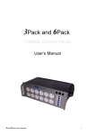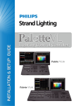
1
Strand Lighting Offices
Philips Strand Lighting - Dallas
10911 Petal Street
Dallas, TX 75238
Tel: 214-647-7880
Fax: 214-647-8031
Philips Strand Lighting - Auckland
19-21 Kawana Street
Northcote, Auckland 0627
New Zealand
Tel: +64 9 481 0100
Fax: +64 9 481 0101
Philips Strand Lighting - New York
267 5th Ave, 4th Floor
New York, NY 10016
Tel: 212-213-8219
Fax: 212-532-2593
Philips Strand Lighting - Europe
Marssteden 152
Enschede 7547 TD
The Netherlands
Tel: +31 53 4500424
Fax: +31 53 4500425
Philips Strand Lighting - Asia Limited
Room 6-10, 20/F Delta House 3 On Yiu Street
Shatin, N.T. Hong Kong
Tel: + 852 2757 3033
Fax: + 852 2757 1767
Website:
www.strandlighting.com
The material in this manual is for information purposes only and is subject to change without notice. Philips Strand
Lighting assumes no responsibility for any errors or omissions which may appear in this manual. For comments and
suggestions regarding corrections and/or updates to this manual, please visit the Philips Strand Lighting web site at
www.strandlighting.com or contact your nearest Philips Strand Lighting office.
El contenido de este manual es solamente para información y está sujeto a cambios sin previo aviso. Philips Strand
Lighting no asume responsabilidad por errores o omisiones que puedan aparecer. Cualquier comentario, sugerencia
o corrección con respecto a este manual, favor de dirijirlo a la oficina de Philips Strand Lighting más cercana.
Der Inhalt dieses Handbuches ist nur für Informationszwecke gedacht, Aenderungen sind vorbehalten. Philips
Strand Lighting uebernimmt keine Verantwortung für Fehler oder Irrtuemer, die in diesem Handbuch auftreten. Für
Bemerkungen und Verbesserungsvorschlaege oder Vorschlaege in Bezug auf Korrekturen und/oder
Aktualisierungen in diesem Handbuch, moechten wir Sie bitten, Kontakt mit der naechsten Philips Strand LightingNiederlassung aufzunehmen.
Le matériel décrit dans ce manuel est pour information seulement et est sujet à changements sans préavis. La
compagnie Philips Strand Lighting n'assume aucune responsibilité sur toute erreur ou ommission inscrite dans ce
manuel. Pour tous commentaires ou suggestions concernant des corrections et/ou les mises à jour de ce manuel,
veuillez s'il vous plait contacter le bureau de Philips Strand Lighting le plus proche.
Note: Information contained in this document may not be duplicated in full or in part by any person without prior written
approval of Philips Strand Lighting. Its sole purpose is to provide the user with conceptual information on the equipment
mentioned. The use of this document for all other purposes is specifically prohibited.
Document Number: 2-450203-020
Version as of: 29 August 2011
N21 ShowNet Node Installation & User’s Manual
©2011 Philips Group. All rights reserved.
N21 ShowNet Node
Installation & User’s Manual
IMPORTANT INFORMATION
Warnings and Notices
When using electrical equipment, basic safety precautions should always be followed including the following:
a. READ AND FOLLOW ALL SAFETY INSTRUCTIONS.
b. For indoor, dry locations use only. Do not use outdoors.
c. Do not mount near gas or electric heaters.
d. Equipment should be mounted in locations and at heights where it will not readily be subjected to
tampering by unauthorized personnel.
e. The use of accessory equipment not recommended by the manufacturer may cause an unsafe
condition.
f. Not for residential use. Do not use this equipment for other than its intended use.
g. Refer service to qualified personnel.
SAVE THESE INSTRUCTIONS.
WARNING: You must have access to a main circuit breaker or other power disconnect device
before installing any wiring. Be sure that power is disconnected by removing fuses or turning the
main circuit breaker off before installation. Installing the device with power on may expose you to
dangerous voltages and damage the device. A qualified electrician must perform this installation.
WARNING: Refer to National Electrical Code® and local codes for cable specifications. Failure to
use proper cable can result in damage to equipment or danger to personnel.
WARNING: This equipment is intended for installation in accordance with the National Electric
Code® and local regulations. It is also intended for installation in indoor applications only. Before
any electrical work is performed, disconnect power at the circuit breaker or remove the fuse to avoid
shock or damage to the control. It is recommended that a qualified electrician perform this
installation.
Additional Resources for DMX512
For more information on installing DMX512 control systems, the following publication is available for purchase
from the United States Institute for Theatre Technology (USITT), "Recommended Practice for DMX512: A Guide
for Users and Installers, 2nd edition" (ISBN: 9780955703522). USITT Contact Information:
USITT
6443 Ridings Road
Syracuse, NY 13206-1111 USA
1-800-93USITT
www.usitt.org
Philips Strand Lighting Limited Two-Year Warranty
Philips Strand Lighting offers a two-year limited warranty of its products against defects in materials or
workmanship from the date of delivery. A copy of Philips Strand Lighting two-year limited warranty containing
specific terms and conditions can be obtained from the Philips Strand Lighting web site at www.strandlighting.com
or by contacting your local Philips Strand Lighting office.
1
Installation & User’s Manual
N21 ShowNet Node
TABLE OF CONTENTS
Strand Lighting Offices .......................................................................................................................... Inside Front Cover
IMPORTANT INFORMATION
Warnings and Notices......................................................................................................................................................... 1
Additional Resources for DMX512.................................................................................................................................... 1
Philips Strand Lighting Limited Two-Year Warranty........................................................................................................ 1
TABLE OF CONTENTS
PREFACE
About this Manual ...................................................................................................................................................................... 3
Getting Started ............................................................................................................................................................................ 3
Unpack N21 Node .............................................................................................................................................................. 3
N21 SHOWNET NODES - OVERVIEW
N21 ShowNet Node Components............................................................................................................................................... 4
Portable Models .................................................................................................................................................................. 4
Rackmount Models ............................................................................................................................................................. 4
INSTALLATION
Power Requirements ................................................................................................................................................................... 5
Portable Models (65151, 65152, 65153, 65153-P)............................................................................................................. 5
Rackmount Models (65154) ............................................................................................................................................... 5
Connecting a DMX512 Network................................................................................................................................................ 5
Installation - 65151 / 65153 Back Boxes.................................................................................................................................... 5
Installation - 65151 Flush Mounting .......................................................................................................................................... 5
Installation - 65153 Surface Mounting ....................................................................................................................................... 6
Installation - 65154 Rack Mounting ........................................................................................................................................... 6
OPERATION
Overview..................................................................................................................................................................................... 7
N21 Node Configuration ............................................................................................................................................................ 7
Pre-Configuring N21 Network Nodes ................................................................................................................................ 7
Configuring the N21 Network Node .................................................................................................................................. 8
Node Button........................................................................................................................................................................ 8
Net Button........................................................................................................................................................................... 9
DMX A Button ................................................................................................................................................................... 9
DMX B Button.................................................................................................................................................................. 10
N21 NODE LCD DISPLAY
Boot Screen............................................................................................................................................................................... 11
Main Screen .............................................................................................................................................................................. 11
Network Configuration Screen 1 .............................................................................................................................................. 12
Network Configuration Screen 2 .............................................................................................................................................. 12
Network Link Screen ................................................................................................................................................................ 12
Node Status Screen 1 ................................................................................................................................................................ 13
Node Status Screen 2 ................................................................................................................................................................ 13
DMX512 Port A Configuration Screen .................................................................................................................................... 13
DMX512 Port B Configuration Screen .................................................................................................................................... 14
LCD Display Screen Icons ....................................................................................................................................................... 14
N21 SHOWNET NODE WEB PAGE
Web Page Description............................................................................................................................................................... 15
Web Page Example ................................................................................................................................................................... 15
PRODUCT CARE
Cleaning and Care Instructions................................................................................................................................................. 16
Product Support ........................................................................................................................................................................ 16
TECHNICAL SPECIFICATIONS
Electrical Specifications ........................................................................................................................................................... 17
Environmental Specifications ................................................................................................................................................... 17
Mechanical Specifications ........................................................................................................................................................ 17
2
TABLE OF CONTENTS
N21 ShowNet Node
Installation & User’s Manual
PREFACE
1. About this Manual
The document provides installation and operation instructions for the following products:
• N21 ShowNet Node, 2-Port, POE, 2-Gang (catalog number 65151)
• N21 ShowNet Node, 2-Port, POE, SN110 Retrofit (catalog number 65152)
• N21 ShowNet Node, 2-Port, POE, with Surface Mount Box (catalog number 65153)
• N21 ShowNet Node, 2-Port, POE, with Portable Mount Back Box, C-Clamp/U-Bolt Hardware (catalog number
65153-P)
• N21 ShowNet Node, 4-Port, 1U Rackmount Enclosure & AC Adapter (catalog number 65154)
Please read all instructions before installing or using this product. Retain this manual for future reference. Additional
product information and descriptions may be downloaded at www.strandlighting.com.
2. Getting Started
Unpack N21 Node
Unpack the node from the packaging and check that all components are contained within. If any parts are missing, or
damaged, please contact the carrier and your nearest Philips Strand Lighting office.
N21 ShowNet Node (catalog number 65151):
• N21 ShowNet Node, 2 Port, POE, 2-Gang
• Installation & User’s Manual (this document)
N21 ShowNet Node (catalog number 65152):
• N21 ShowNet Node, 2-Port, POE, SN110 Retrofit
• Installation & User’s Manual (this document)
N21 ShowNet Node (catalog number 65153):
• N21 ShowNet Node, 2-Port, POE, with Surface Mount Box
N21 Portable Nodes
• Installation & User’s Manual (this document)
N21 ShowNet Node (catalog number 65153-P):
• N21 ShowNet Node, 2-Port, POE, with Portable Back Box
• C-Clamp
• U-Bolt Mounting Hardware
• Installation & User’s Manual (this document)
N21 ShowNet Node (catalog number
65154):
• N21 ShowNet Node, 4-Port, 1U Rackmount
Enclosure
• AC to DC Power Supply
• Installation & User’s Manual (this document)
N21 Rackmount Nodes
About this Manual
3
N21 ShowNet Node
Installation & User’s Manual
N21 SHOWNET NODES - OVERVIEW
1. N21 ShowNet Node Components
Portable Models
LCD Display
(for more information, see "N21
NODE LCD DISPLAY" on
page 11)
DMX512 (XLR5F)
Connections (x2)
NOTE: Ethernet connection not shown. On rear of unit for 65151, 65152, and 65153 nodes. On side for 65153-P node.
Hardware for 65153-P node not shown - refer to "Mechanical Specifications" on page 17 for more information.
Rackmount Models
AC to DC Power Supply
(included with unit)
Node 2 Ethernet
(RJ45) Connection
Node 1 Ethernet
(RJ45) Connection
Node 1 DMX512 (F)
Connections (x2)
Node 2 DMX512 (F)
Connections (x2)
Rackmount
Ears
4
ON / OFF
Power Switch
Node 1 LCD Display
Node 2 LCD Display
(for more information, see "N21
NODE LCD DISPLAY" on
page 11)
(for more information, see "N21
NODE LCD DISPLAY" on
page 11)
N21 SHOWNET NODES - OVERVIEW
N21 ShowNet Node
Installation & User’s Manual
INSTALLATION
1. Power Requirements
Portable Models (65151, 65152, 65153, 65153-P)
All portable N21 ShowNet Nodes are powered from a POE (Power Over Ethernet) compatible Ethernet Switch or
midspan/endspan POE injector using IEEE P802.3af-2003 power. The POE should be +48vdc. The unit shall draw
45mA with backlight at full.
Rackmount Models (65154)
All rackmount N21 ShowNet Nodes are powered from the provided AC to DC Power Supply. The power supply
converts AC input voltage to +5vdc. The nominal current draw at +5vdc is 500mA with both LCD display backlights
at full.
2. Connecting a DMX512 Network
Basic DMX512 installation consists of connecting a N21 ShowNet Node to a DMX512 controller in "daisy-chain"
fashion. A cable runs from the DMX512 controller to a N21 ShowNet Node and to other DMX512 devices in the
system. Note, the N21 ShowNet Node does not have to be first device in the DMX512 signal chain.
Note: The portable N21 Node has two female 5-pin XLR connectors for DMX512 Out. When a node port is
configured for DMX512 In, a gender-changer (by others) is required to convert the port from female to male.
For more information on DMX512 networking and systems, refer to "Additional Resources for DMX512" on page 1.
For N21 ShowNet Node configuration and operation, refer to "OPERATION" on page 7.
PUSH
DMX512 Connections
DMX512 Signal
1
5
2
4
XLR Pin
Common (Drain)
1
DMX512 -
2
DMX512 +
3
Note: Remaining pins on connector are not used.
3
N21 Node DMX512 Connector
3. Installation - 65151 / 65153 Back Boxes
The 65151 N21 Node includes the faceplate and electronics only and is suitable for flush wall mounting. The back
box (RACO 696 equivalent) is supplied by others.
The 65153 N21 Node is housed within a metal back box supplied by Strand Lighting and is suitable for surface wall
mounting.
Both models are intended for permanent installations using earthed conduit to carry the network cable. The unit
should not be operated without the earthed metal conduit as it may fail EMC compliance.
4. Installation - 65151 Flush Mounting
To flush mount a 65151 N21 Node:
Power Requirements
5
N21 ShowNet Node
Installation & User’s Manual
Step 1. Prepare the wall by cutting an appropriate sized hole for the back box (RACO 696 or equivalent - supplied
by others).
Step 2. Determine the most suitable position for cable entry and
drill a hole in the back box for cable entry. Ensure that 65151 N21 ShowNet Node, 2-Port, POE, 2-gang
the hole allows cables to enter the box without fouling
4.5 in
any components within the box when the node
114.3 mm
electronics are installed.
Step 3. Insert the back box in the wall and secure the conduit to
the back box.
3.625 in
92.1 mm
4.625 in
117.5 mm
Step 4. Leave the cables in the back box ready for connection.
5. Installation - 65153 Surface Mounting
To surface mount a 65153 N21 Node:
Back Box
(by others)
Step 1. Remove the four (4) screws from the front panel and lift
the front plate upwards and away from the back box. (Keep the screws safe for later use).
Step 2. Determine the most suitable position for the cable entry and drill a hole in the back box for cable entry.
Ensure that the hole allows cables to enter the box 65153 N21 ShowNet Node, 2-Port, POE, with Surface Mount Box
without fouling any components within the box
when the node electronics are installed.
4.5 in
3.625 in
114.3 mm
Step 3. Ensure that the back box is level by placing a spirit
level on top of the box and mark the four mounting
holes.
Step 4. Drill four (4) holes in the wall and secure the back
box to the wall using screws and suitable hardware.
92.1 mm
4.625 in
117.5 mm
Step 5. Secure the conduit to the back box and leave the
cables in the back box ready for connection.
Surface
Mount Box
6. Installation - 65154 Rack Mounting
To rack mount a 65154 N21 Node:
Step 1. Before installing, you will need four (4) rack screws that fit your specific rack (by others), at least 1U of
rack space available in the rack, and a place to connect the AC to DC power supply.
Step 2. Connect AC to DC power supply to unit. Do not connect to AC supply source at this time.
Step 3. Slide 65154 N21 Node into rack and secure with four rack screws.
Step 4. With unit’s power switch OFF, connect AC to DC supply to AC source.
65154 N21 ShowNet Node, 4-Port, 1U Rack Mount Enclosure with AC Adapter
AC to DC Power Supply
(included with unit)
REAR VIEW
19.00 in / 482.60 mm
6.50 in / 165.10 mm
1.72 in / 43.64 mm
FRONT VIEW
6
INSTALLATION
SIDE VIEW
N21 ShowNet Node
Installation & User’s Manual
OPERATION
1. Overview
The N21 Dual and four Port Ethernet DMX512 Nodes provide compact and cost effective networking solutions for
lighting facilities of any size.
Based on a 32-Bit ARM processor, all N21 nodes utilize the Linux operating system for stable 10/100 BaseT
operation. Nodes may be configured with any PC or Strand Lighting Wireless Focus Remote utilizing the Mozilla
FireFox web browser if the network is utilizing a wireless router.
The N21 Network Node is available in five different configurations. For available models, refer to "About this
Manual" on page 3.
2. N21 Node Configuration
Pre-Configuring N21 Network Nodes
N21 network nodes are configured at the factory with common default values. It is therefore necessary to change the
network configuration for each node before it is installed onto the network. It is logical that the configuration of the
DMX512 ports and the LCD setting should be done at the same time and each N21 Node labeled with its IP Address
ready for installation in the appropriate back box, auxiliary rack or dimmer rack.
The network configuration for N21 nodes is as follows:
Field
Value
Node Name
N21
IP Address
192.168.0.XX (XX will be a value between 0 and 255)
IP Netmask
255.255.255.0
IP Gateway
0.0.0.0
Select the Network configuration page as follows:
With the N21 Node powered and connected to a network, open the browser (see note below) window and enter the IP
Address of the N21 Node followed by "/mini" to display the configuration pages shown in "Net Button" on page 9
See "N21 SHOWNET NODE WEB PAGE" on page 15 for an example of a standard web page.
Note: N21 nodes can only be configured using a FireFox web browser. You may download the latest version of this
free software at http://www.mozilla.com/en-US/firefox/.
Overview
7
N21 ShowNet Node
Installation & User’s Manual
Configuring the N21 Network Node
The N21 Node can be configured as shown herein. These examples are using the http:/
/192.168.0.xxx/mini/ webpage to configure the node. An example of a full web page
screen can be seen in "N21 SHOWNET NODE WEB PAGE" on page 15. Shown on
the Configuration page is:
Button
Node
Net
Meaning
Accesses information specific to the node
Accesses information specific to the network
DMX A
Accesses information specific to DMX A
DMX B
Accesses information specific to DMX B
Update
Updates the node with the current (or shown) information
N21 Node Configuration
Node Button
When the Node button is pressed, the following options are available as shown.
Having set up the Node options, press Update button to save the Node
configuration.
Option
Name
A unique identifier character string of up to 16 characters. This can be
any name used to identify the node on the network.
Location
A unique identifier character string of up to 16 characters. This can be
any name used to identify the location of the facility or PoE port
connected to the Node.
Breaker / Port
A unique identifier character string of up to 16 characters. This can be
any name used to identify the power breaker.
Passcode
The Passcode Field in the Node Button Screen is not used. Please read
this section carefully for Passcode usage.
The default passcode (2606) is required to access node parameters or to
save changes made to settings. After the Update button is pressed, the
passcode must be entered when prompted to save any changes.
NOTE: The passcode must be entered on the standard web page to be
Authorized to make changes. This is located at HOME/AUTHORIZE
(see "Web Page Description" on page 15 for more information).
Backlight Idle
Adjusts the low backlight level. The range is between 0 and 10. Levels
set below 3 are likely to be invisible. FACTORY RECOMMENDED
SETTING: 3 (SEE WARNING).
Backlight Active
Adjusts the high backlight level. The range is between 3 and 10. The
high level is used when the page button has been pressed. FACTORY
RECOMMENDED SETTING: 8 (SEE WARNING).
Backlight Hold Time
Adjusts the time (in seconds) that the display should hold the high
backlight level after a button press. The range is between 10 and 600
seconds. This also sets the menu time-out. FACTORY
RECOMMENDED SETTING: 30 (SEE WARNING).
Blink LCD
No Mux Hold Time
No Mux Netslot
8
Meaning
OPERATION
Selecting this option will cause the LCD screen to blink.
This option allows you to select the Hold Time should the DMX512 signal
be interrupted. The Hold Time will ‘freeze’ the current look on stage until
the time runs out, at which time the lights will fade to black. The minimum
Hold Time is 10 Minutes. The Maximum Hold Time is Infinite (no end
time).
The Netslot is used to monitor the loss of the DMX512 signal /
communications.
Node Button Screen
WARNING! Adjusting the
brightness level above the
recommended settings as
shown above may result in
display issues.
N21 ShowNet Node
Installation & User’s Manual
Net Button
When the Net button is pressed, the following options are available as shown. Having
set up the Net options, press Update button to save the Node configuration.
Option
Hostname
IP Address
Meaning
A unique identifier character string of up to 20 characters. This can be
any name used to identify the Host Name on the network.
A unique identifier on a network using the TCP/IP protocol to route data
to a particular node within the network. The format of an IP Address is a
32-bit numeric address comprising four numbers separated by periods.
Each number can be 0 to 255. The first three sets of numbers on a Class
C network identify the network and the last set of numbers identifies the
node. See "Pre-Configuring N21 Network Nodes" on page 7 for
additional information.
Net Button Screen
NOTE: If the IP address on the node is changed, the new IP address will
need to be entered on the browser to load the new address.
IP Netmask
This is used only in large networks comprising subnetworks. Refer to
your system network administrator.
NOTE: Default Netmask is: 255.255.255.0.
Gateway
This is used only in large networks that require routing between subnetworks. Refer to your system network administrator.
NOTE: Default Gateway is: 0.0.0.0
DMX A Button
When the DMX A button is pressed, the following options are available as shown.
Having set up the DMX A options, press Update button to save the Node
configuration.
Option
Meaning
DMX A Label
This field contains a character string of up to eight (8) characters used to
identify the function of the DMX512 A Port.
For DMX A Mode, there are five subsettings:
DMX A Mode
Off: Turns port OFF
DMX out: Sets Port for DMX512 output
DMX in: Sets port for DMX512 input
SVN: Sets port for Strand Vision-Net Protocol*
SMX: Sets port for Strand Report-Net/Outlook/SWC*
NOTE: *SVN and SMX are factory test settings and SHOULD NOT be
altered or changed.
DMX A In Start Slot
Enter the start slot number for DMX512 A Input
DMX A In End Slot
Enter the end slot number for DMX512 A Input
DMX A In Starting Net
Slot
DMX A Monitor Slot
Start, End and Net Slot
Fields
DMX A Out Start Slot
DMX A Button Screen
Start number of the Net Slot for DMX512 A Input
This field determines which of the 512 slots from the DMX512 port are
displayed on the status bar graph at the sides of the LCD screen. Any
slots between 1 and 512 can be entered.
These fields allow you to enter a range of DMX outputs to be patched to
a range of Netslots for each DMX port. Initially, the window permits two
ranges of DMX output slots to be entered. However, when the second
range is entered and the UPDATE button is pressed, another blank row
is added, permitting another range of outputs to be entered for another
Netslot range. This will continue until all ranges of outputs have been
entered.
Enter the start slot number of the DMX512 range.
N21 Node Configuration
9
N21 ShowNet Node
Installation & User’s Manual
Option
DMX A Out End Slot
Meaning
Enter the end slot number of the DMX512 range
Netslot
Enter the Netslot start number.
Priority
Each Netslot can be set as one (1) of sixteen (16) priorities by selecting
from the drop-down menu. A DMX512 slot can be patched to multiple
Netslots with each Netslot assigned to a different priority. The DMX512
slot outputs the level of the Netslot with the highest priority if HTP (see
below) is not selected.
HTP (Highest Takes
Precedence)
When a DMX512 slot is patched to multiple Netslots with different
priorities, selecting HTP makes the DMX512 slot output the highest level
of the multiple Netslots, ignoring the priority settings.
DMX B Button
When the DMX B button is pressed, the following options are available as shown.
Having set up the DMX B options, press Update button to save the Node
configuration.
Option
Meaning
DMX B Label
This field contains a character string of up to eight (8) characters used to
identify the function of the DMX512 B Port.
For DMX B Mode, there are five subsettings:
DMX B Mode
Off: Turns port OFF
DMX out: Sets Port for DMX512 output
DMX in: Sets port for DMX512 input
SVN: Sets port for Strand Vision-Net Protocol*
SMX: Sets port for Strand Report-Net/Outlook/SWC*
NOTE: *SVN and SMX are factory test settings and SHOULD NOT be
altered or changed.
DMX B In Start Slot
Enter the start slot number for DMX512 B Input
DMX B In End Slot
Enter the end slot number for DMX512 B Input
DMX B In Starting Net
Slot
DMX B Monitor Slot
Start, End and Net
Slot Fields
10
Start number of the Net Slot for DMX512 B Input
This field determines which of the 512 slots from the DMX512 port are
displayed on the status bar graph at the sides of the LCD screen. Any
slots between 1 and 512 can be entered.
These fields allow you to enter a range of DMX outputs to be patched to
a range of Netslots for each DMX port. Initially, the window permits two
ranges of DMX output slots to be entered. However, when the second
range is entered and the UPDATE button is pressed, another blank row
is added, permitting another range of outputs to be entered for another
Netslot range. This will continue until all ranges of outputs have been
entered.
DMX B Out Start Slot
Enter the start slot number of the DMX512 range.
DMX B Out End Slot
Enter the end slot number of the DMX512 range
Netslot
Enter the Netslot start number.
Priority
Each Netslot can be set as one (1) of sixteen (16) priorities by selecting
from the drop-down menu. A DMX512 slot can be patched to multiple
Netslots with each Netslot assigned to a different priority. The DMX512
slot outputs the level of the Netslot with the highest priority if HTP (see
below) is not selected.
HTP (Highest Takes
Precedence)
When a DMX512 slot is patched to multiple Netslots with different
priorities, selecting HTP makes the DMX512 slot output the highest level
of the multiple Netslots, ignoring the priority settings.
OPERATION
DMX B Button Screen
N21 ShowNet Node
Installation & User’s Manual
N21 NODE LCD DISPLAY
This section describes the various LCD Display screen on N21 ShowNet Nodes.
1. Boot Screen
During the boot-up process, the LCD screen display shows the Strand Lighting logo. After the boot-up process is
complete, press the Page button to scroll through the eight available screens.
Note: The Page button is not active until the boot-up process is complete.Nte,
Page Button
LCD Display
2. Main Screen
Below is a graphical representation of the N21 ShowNet Node LCD Display main screen.
Network Status
(Active or Inactive)
Node Name
(user-assigned name)
BALLROOM
Network Inactive
SL Elec.
SR Elec.
DMX Out
DMX In
Slot Monitor
Bar Graphs
Port A & B Defined As
(DMX In or DMX Out)
Port A & B Labels
(user-assigned names)
Boot Screen
11
N21 ShowNet Node
Installation & User’s Manual
3. Network Configuration Screen 1
Below is a graphical representation of the N21 ShowNet Node LCD Display network configuration screen 1.
Node Configuration
Page 1
Node Hostname
Network Config 1
Version: 2.1.7
N21_71
IP = 192.168. 0. 80
Node Firmware
Version
Node IP Address
4. Network Configuration Screen 2
Below is a graphical representation of the N21 ShowNet Node LCD Display network configuration screen 2.
Node Configuration
Page 2
Node Gateway
Network
Mask
GW
MAC
Config 2
= 255.255.255. 0
= 0. 0. 0. 0
= 00:E0:01:01:13:64
Node Netmask
Node MAC Address
5. Network Link Screen
Below is a graphical representation of the N21 ShowNet Node LCD Display network link screen.
Network Link Page
Link Speed
(10 = 10BaseT,
100 = 100BaseT)
Network Link
Link_present = 0
Link_speed = 10
Link_duplex = Half
Link Present?
(0 = No, 1 = Yes)
Link Duplex
(Half or Full)
12
N21 NODE LCD DISPLAY
N21 ShowNet Node
Installation & User’s Manual
6. Node Status Screen 1
Below is a graphical representation of the N21 ShowNet Node LCD Display node status screen 1.
Node Status Page 1
Node Time
Node Status 1
06:21:22
Up-time:
0:11
20oC
Node Temperature
(in Fahrenheit or
Celsius)
Current Node
Operational Time
7. Node Status Screen 2
Below is a graphical representation of the N21 ShowNet Node LCD Display node status screen 2.
Node Status Page 2
Node Status 2
Memory (Total and
Available)
Memory:
Flash:
Total
63220kB
14336kB
Free
58768kB
10364kB
Flash Memory
(Total and Available)
8. DMX512 Port A Configuration Screen
Below is a graphical representation of the N21 ShowNet Node LCD Display DMX512 port A configuration screen.
Port A (DMX512 A)
Configuration
Port A Config
Port Label (name)
SL Elec.
Port Inactive
DMX Out
Port Setting
(DMX In, DMX Out,
SVN, SMX, or Off)
Port Status (Active or
Inactive)
Node Status Screen 1
13
N21 ShowNet Node
Installation & User’s Manual
9. DMX512 Port B Configuration Screen
Below is a graphical representation of the N21 ShowNet Node LCD Display DMX512 port B configuration screen.
Port B (DMX512 B)
Configuration
Port B Config
Port Label (name)
DMX In
SR Elec.
1-512
0001
Port Inactive
Port Setting
(DMX In, DMX Out,
SVN, SMX, or Off)
Port Status (Active or
Inactive)
Note: DMX512 Port A and Port B offer the same number of settings and configurations. The aforementioned
settings are shown for contrast.
10. LCD Display Screen Icons
The following describes the five screen icons that may appear on the N21 ShowNet Node LCD Display.
Icon Symbol
Icon Name
L
Status Link
The "L" will be present when the N21 Node is
linked with an Ethernet port on a switch
Link Speed
10Mbps will show a white "S" on a blue
background.
100Mbps will show a blue "S" on a white
background.
Link Duplex
Half duplex will show a white "F" on a blue
background.
Full duplex will show a blue "F" on a white
background.
Down Arrow
Indicates DMX512 outputting traffic. The Down
Arrow icon is shown when the port is actively
transmitting DMX512 data.
S
F
Up Arrow
N21 Node LCD Display
BALLROOM
Network Inactive
SL Elec.
SR Elec.
DMX Out
DMX In
14
N21 NODE LCD DISPLAY
Comments
Indicates DMX512 incoming traffic. The Up Arrow
icon is shown when the port is actively receiving
DMX512 data.
Status Link Icon
Link Speed Icon
Link Duplex Icon
DMX Port A Arrow Icon
DMX Port B Arrow Icon
N21 ShowNet Node
Installation & User’s Manual
N21 SHOWNET NODE WEB PAGE
1. Web Page Description
The web pages are accessed when the IP address for the node is entered. An example is HTTP://192.168.0.71.
Once the Node has been accessed, all of the web pages can be browsed and configured. The web page example is
located under the HOME/SETUP/SYSTEM/PARAMETERS, and provides a single screen to set the majority
of the options of the N21 Node.
Note: Without entering the Authorization Password, the web pages will only provide preview information and
cannot be changed. When the password (2606) is entered under HOME/AUTHORIZE button, the upper screen
will highlight in red that you are Privileged and allow you to edit the fields.
2. Web Page Example
Below is an example of the N21 Node web page.
Web Page Description
15
Installation & User’s Manual
N21 ShowNet Node
PRODUCT CARE
1. Cleaning and Care Instructions
WARNING! All cleaning should be performed with power completely removed from the unit. Never attempt to
open unit. There are no user-serviceable parts. Under no circumstances should ammonia-based cleaners, acetone, or
other harsh solvents be used on or near the N21 ShowNet Node. These types of cleaners or solvents can permanently
damage the unit.
Being a solid-state device, the N21 ShowNet Node requires very little routine maintenance by the user. See
"Warnings and Notices" on page 1 for safety warnings.
• Avoid spillage from liquids. If this occurs switch power off immediately
• Protect from excessive dust or other contaminants
• For indoor use only
• The equipment is designed and manufactured to comply with international safety standards IE950, UL1950 and
CS 950 and is intended for use as part of a lighting control system. It must not be used for any other purpose where
there is a risk of safety to persons.
• The equipment contains power voltages.
• There are no serviceable parts within the N21 Node housing.
• Installation and maintenance of the N21 Node should be undertaken by a suitably qualified person.
2. Product Support
In the event you have any issues with your Strand Lighting product, you may contact your Authorized Strand
Lighting Dealer, Authorized Strand Lighting Service Center, or Strand Lighting Technical Support.
Contact information for Authorized Strand Lighting Dealers and Service Centers is found on the Strand Lighting web
site at www.strandlighting.com or by contacting us at 1.214.647.7880.
Note: A complete listing of "Strand Lighting Offices" is found on the inside cover of this manual.
16
PRODUCT CARE
N21 ShowNet Node
Installation & User’s Manual
TECHNICAL SPECIFICATIONS
1. Electrical Specifications
Portable N21 Node Models (catalog numbers 65151, 65152, 65153 and 65153-P)
Input Voltage:
Input Current:
+48vdc supplied as Power over Ethernet (PoE)
At +48vdc nominal, 45mA (with backlight at full)
Rackmount N21 Node Model (catalog number 65154)
Input Voltage:
Input Current:
+5vdc supplied from an external power supply mounted in the auxiliary rack.
At +5vdc nominal, 350mA typical; 500mA maximum (with backlight at full)
Connectivity
DMX512:
Ethernet:
2 Each, 5-pin female XLR
1 Each, RJ45
2. Environmental Specifications
Operating Temperature:
Storage Temperature:
Humidity:
EMC Emissions:
EMC Immunity:
Safety:
Ethernet:
Markings:
32 to 104ºF / 0 to 40ºC
-40 to 158ºF / -40 to 70ºC
5% - 95% non-condensing
EN50081-1, EN55014
EN50082-1, IEC1000-2-2
EN60950
IEEE
CE Marked
3. Mechanical Specifications
Construction:
Wall Mount:
Rack Mount:
Steel faceplate, unit is designed to fit a standard deep masonry box
Steel enclosure
Weight:
Wall Mount:
Rack Mount:
1.9 lbs / 0.86 kg
4.9 lbs / 2.2 kg
Dimensions:
Wall Mount:
Refer to Figure 1 on page 18.
Rack Mount:
Refer to Figure 2 on page 19.
Electrical Specifications
17
N21 ShowNet Node
Installation & User’s Manual
65151 N21 ShowNet Node, 2-Port, POE, 2-gang
4.5 in
114.3 mm
3.625 in
92.1 mm
4.625 in
117.5 mm
Back Box
(by others)
65152 N21 ShowNet Node, 2-Port, POE, SN110 Retrofit
4.5 in
114.3 mm
3.5 in
88.9 mm
4.625 in
117.5 mm
2-Gang Back Box
(by others)
65153 N21 ShowNet Node, 2-Port, POE, with Surface Mount Box
4.5 in
114.3 mm
3.625 in
92.1 mm
4.625 in
117.5 mm
Surface
Mount Box
Figure 1: Wall Mount Models
18
TECHNICAL SPECIFICATIONS
N21 ShowNet Node
Installation & User’s Manual
65153-P N21 ShowNet Node, 2-Port, POE, with portable mount back box, C-Clamp and U-Bolt Hardware
2-inch
U-Bolt
C-Clamp
NOTE:
65153-P Node shares same dimensions
as 65153 Node.
Ethernet
Connection
3.625 in
92.1 mm
65154 N21 ShowNet Node, 4-Port, 1U Rack Mount Enclosure with AC Adapter
AC to DC Power Supply
(included with unit)
REAR VIEW
19.00 in / 482.60 mm
6.50 in / 165.10 mm
1.72 in / 43.64 mm
FRONT VIEW
SIDE VIEW
Figure 2: Portable Mounting and Rack Mount Models
Note: For complete model specifications, features, etc., refer to the product specification sheet or visit the Philips
Strand Lighting web site at www.strandlighting.com for more details.
Mechanical Specifications
19
Installation & User’s Manual
Notes
20
TECHNICAL SPECIFICATIONS
N21 ShowNet Node
N21 ShowNet Node
Installation & User’s Manual
Notes
Mechanical Specifications
21