1
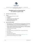
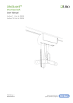
User Manual
QuickRay Sensor USB
110 E. Granada Blvd. Suite 207
Ormond Beach, FL 32176
Ph: 386-672-0450 800-323-2690
Manual Date 10-2014
pg. 1
Table of Contents
Introduction
Indication for Use
Product Description
Unpacking your QuickRay Sensor
Symbols Used in the Manual
General Description
Cable
Housing
Contents
Label
Label Information
Packaging and Environment
Safety and Disposal Procedures
Electrical Safety
X-ray protection
Prevention of Cross-Contamination
Product Disposal
Prevention of Environmental Contamination
Power Supply
Operators and Liability
Installation
Installation Process
Setup Guidelines
Multiple Sensors
Portability
Positioners
Step-by-Step Positioner Instructions
4
4
5
5
5
6
6
6
7
8
9
10
10
10
11
11
11
12
12
12
12
13
13
14
14
14
15
pg. 2
Positioners in the Kit
Sensor Precautions
Care Instructions
Cleaning and Disinfecting Instructions
Recommended Disinfecting Solutions
Mechanical Damage Prevention
Protection from Electrical Damage
Maintenance
Troubleshooting
Specifications
Sensor Architecture
Mechanical Dimensions Size #1
Mechanical Dimensions Size #2
Sensor Sample Images
Image Quality Assurance
Electro Optical Performances
Electro Optical Performances under X-rays
Operating Range
DQE Chart
Index
16
17
17
17-18
19
19-21
21
22
22
22
23
24
25
26
27
27
27
28
29
30-31
pg. 3
1. INTRODUCTION
You have just received your QuickRay digital intra-oral radiology kit. We thank you for purchasing
our product and for the confidence you have in us and hope that our product will give you complete
satisfaction.
We recommend you to read this manual thoroughly before installation; following the guidelines
from installation and usage described in it will exclude risks to the patient and the care team.
Your sensor uses an x-ray sensitive electronic detector that replaces the conventional film used for
the acquisition of radiological intra-oral images. The x-rays are automatically detected by the sensor
which triggers image acquisition. The acquired image is displayed almost instantaneously on the
screen of the computer to which the sensor is connected. These digital images can then be
manipulated, analyzed, saved as files or printed.
The development process of conventional films is thus completely eliminated as well as the possible
influences on image quality; such as the type and age of the chemical product, the temperature of
the baths or the development time.
The sensor is available in two sizes; depending on the kit you have ordered you received a size 1,
a size 2 sensor or both:
•
•
The size 1 sensor allows you to acquire the majority of intra-oral images both vertically and
horizontally.
The size 2 sensor allows you to easily acquire horizontal “bitewing” images.
The instructions and information in this manual refer to both sensor sizes, unless specifically stated.
Caution: Federal law restricts this device to sale by or on the order of a dentist
1.1 Indication for Use
QuickRay USB Sensor is an intraoral digital x-ray detector indicated for dental radiographic
examination and diagnosis of diseases of the teeth, jaw, and oral structure through exposure of a
digital x-ray image receptor to ionizing radiation from an extra-oral x-ray source that is not part of
the system.
pg. 4
1.2 Product Description
An X-ray image sensor is positioned in the patient’s mouth just like intraoral film. There is no
electrical or physical connection between QuickRay and the x-ray generator. Images are
automatically acquired when x-rays are present in a dose which is perceptible to the sensor.
Digital x-ray images are quickly displayed on the screen. Images can be optimized for viewing via
imaging software, stored as image files, and printed out on a suitable printer if desired. Apteryx is
one example of a dedicated software that employs a number of utilities for optimizing viewing and
printing of images.
The QuickRay must be connected to a PC through the standard USB port.
1.3 Unpacking your QuickRay Sensor
The QuickRay sensor is carefully inspected and packaged prior to shipment. If the sensor was
shipped to you, please remove the contents of the shipping container and be sure to identify and
directly locate each of the components listed below.
NOTE: If the package arrives with any damage or missing components, please notify your dealer immediately
(within 24 hours) and you will be instructed as to how this should be handled.
CHECK LIST BEFORE USE
Make sure the kit is complete with the following items: Sensor, Sensor Holder Trial Kit, Sensor Covers, Wall
Bracket, Sensor Software & Drivers CD-ROM and Sensor Correction File CD-ROM and Acceptance Form.
Please notify the dealer immediately if the kit is incomplete.
Once the system is installed make sure to complete the Acceptance Form and send this in to activate your 2
year warranty date.
1.4 Symbols Used in the Manual
Warning Alerts the operator that failure to follow the procedure could cause
bodily injury or death.
Caution Alerts the operator that failure to follow the procedure could cause
damage to the equipment or cause loss of data.
Important
Provides advice for the operator regarding use of the device or a process.
NOTE
Highlights important or unusual points.
pg. 5
1.5 General Description
The intra oral sensor includes the following sub elements:
- CMOS image sensor chip
- Scintillator
- Electronic substrate (electronic circuitry carrier + proximity electronics)
- Flexible cable with end connector
- Watertight housing
- Shielding foils and shock absorbers
Scintillator
X-rays
CMOS chip
Shock
Absorbers
Ceramic
Support
And
Electronic
Shielding
Housing
Cable + Connector
Intra-oral Module Overview
1.6 Cable
Cable outer material is polyurethane
Cable diameter: 3.5 mm +/- 0.1 mm
Cable length: 3m +0 / -6cm
1.7 Housing
Housing material is polyamide: PA 12 – 30 FV Grilamid LV3H Black
Envelope protection: IP67 (cf IEC 60529)
pg. 6
2. Contents
Size 1.0 = Image area / outer dimensions
= 600 mm / (36.73 mm x 24.35mm)
= 67.1%
Size 2.0 = Image area / outer dimensions
= 900 mm / (42.8 mm x 30.5 mm)
= 69.02%
___________________________________________________________________________
NOTE: The QuickRay sensor is individually marked with a serial number printed on a sticker
and put around the cable. The sticker is located close to the USB connector. (See picture
below)
___________________________________________
_______________________________________
Sensor Correction File CD-ROM
pg. 7
__________________________________________________________________________________________
When you receive the QuickRay sensor, if the kit is not complete or you have
any damage due to shipping, please notify us immediately at Denterprise
International, Inc. 800-323-2690.
2.1 Label
QuickRay USB Size 1/Size 2
Direct USB Intraoral Sensor
Manufacturer: Denterprise International, Inc.
110 E. Granada Blvd. Suite 207
Ormond Beach, FL 32176
800-323-2690
ASSEMBLED IN USA
Intended for dental radiographic examination and diagnosis of
diseases of the teeth, jaw, and oral structure
Nominal Voltage & current (USB): 5V
100mA
Max Current: 0.15A
93%
5%
IP 67
Caution: Federal law restricts this device to sale by or on the order of a dentist
35oC
5oC
2.2 Label Information
pg. 8
Description
Manufacturer name: Denterprise International, Inc.
Address: 110 E Granada Blvd. Suite 207
Ormond Beach, FL 32176
Tel: 1-800-323-2690
Fax: 1-855-235-7902
www.denterpriseintl.com
[email protected]
___________________________________________________________________________
Label Traceability
Label Containing:
QuickRay Sensor
Product name
Serial Number of Sensor
Date Manufactured
Consult instructions for use
BF Type Equipment
Product must be collected separately
85%
Humidity storage conditions – 93%
Storage conditions
-40 degrees F to 100 degrees F
IP 67
Dust resistant; Water resistant
pg. 9
2.3 Packaging and Environment
Transport, storage and environment: the QuickRay sensor is delivered in a non- sterile package. It
is shipped in a protective package to prevent the sensor from physical impact or damage.
Storage conditions:
•
•
•
Storage temperature
Storage humidity
-40 degrees F – 105 degrees F
up to 93%
Operating range:
•
•
•
Room temperature
Room humidity
Operating temperature
40 degrees F -- 95 degrees F
5% -- 85%
40 degrees -- 100 degrees F
NOTE: Should a return to the distributor be necessary, make sure to package the QuickRay sensor
in the original packaging.
All sensors are shipped with its documentation. Please contact your distributor for a replacement
manual if this documentation is lost.
3. Safety and Disposal Procedures
The QuickRay sensor must be installed and used in accordance with the safety regulations and
instructions for use supplied in this User Manual, for the purposes and applications for which it is
intended.
Modifications and/or additions to the QuickRay must always comply with standards and recognized
rules of good workmanship.
3.1 Electrical Safety
This product must be used only in rooms or areas which comply with all laws and regulations
applicable to electrical safety in medical premises, such an IEC standards regarding use of an
additional ground terminal for potential connections.
•
The QuickRay sensor conforms to electrical and safety standard IEC 60601-1 (Medical
Electrical Equipment, Part I: General requirements for basic safety and essential
performance).
pg. 10
•
The QuickRay sensor conforms to electrical and safety standard IEC 60601-1-2 (Medical
Electrical Equipment, Part 1-2: General requirements for basic safety and essential
performance – collateral standard: Electromagnetic compatibility).
•
QuickRay sensor is not suitable to be operated in an anesthetic gas environment.
•
All IT components are to be placed OUTSIDE the patient environment. IT components
placed INSIDE the patient environment, due to customer site requirement, must conform to
other basic standards. IEC 60601-1 defines the “Patient environment” as “any volume in
which intentional or unintentional contact can occur between a patient and parts of the ME
Equipment or ME System or between a Patient and other persons touching parts of the ME
Equipment or ME System.”
Warning ______________________________________________
DO NOT CONTINUE TO USE THE SENSOR IF THERE IS VISIBLE DAMAGE TO THE
SENSOR HOUSING AND/OR CABLE.
________________________________________________________________________
3.2 X-ray Protection
The rules of dental radiography still apply to digital x-ray systems. Please continue to use protection
for your patients. As a clinician, clear the immediate area when exposing the sensor.
3.3 Prevention of Cross-Contamination
To help prevent cross-contamination between patients, place a new hygienic barrier on the sensor
for each new patient. The hygienic barrier must cover the sensor and at least 3-4 inches (7-10 cm)
of the cable.
3.4 Product Disposal
The sensor contains a small amount of lead, similar to the lead foil used in dental intraoral xray film. The sensor head needs to be disposed of carefully, so please contact your dealer or
supplier for further information about product disposal at the end of the product’s lifetime. The
cable and connector have to be recycled by an electronic waste processing facility.
pg. 11
3.5 Prevention of Environmental Contamination
Dispose of sheaths and other consumables following the normal dental office procedure for
biomedical waste.
4. Power Supply
The power to the QuickRay sensor is provided directly by the power supply of the USB cable
connecting it to the computer.
The USB port shall support USB 2.0 High speed mode.
5. Operators and Liability
The QuickRay sensor must be used by a dental practitioner and trained technical staff.
•
The connection box should never be opened by the user. Only the manufacturer is authorized to
open and make repairs to the sensor or box. Return the equipment to your distributor in case of
malfunction.
The manufacturer will not be liable if:
•
Interventions or repairs have been made by persons without the authorization of the manufacturer
or distributor and are not part of accepted interventions.
•
The equipment is used with an installation that is not compliant with the applicable standards and
decrees—in particular when not compliant with the stands relating to the security rules for electro
medical systems. Make sure the installation of the equipment is compliant with the applicable
regulations.
6. Installation
Installation precautions:
As the intra-oral sensor is situated inside the patient environment, your computer must
necessarily comply with standard IEC 60601-1, or your installation including the
computer must have been rendered compliant with stand IEC 60601-1. You can connect the sensor
to your computer without additional precautions once your complete installation is compliant with
standard IEC 60601-1-1.
pg. 12
The QuickRay sensor is an electrical medical device requiring special precautions
regarding electromagnetic compatibility. Please observe the recommendations in this
manual during the commissioning and use of the equipment. NOTE: To avoid interferences in the
image, do not use the system close to strong magnetic fields and avoid proximity to electrostatic
emission sources.
The sensor must be handled with care, minimizing the twisting, pulling and bending of
the attachment cable. DO NOT step or roll on the cable. DO NOT pull on the cable itself
but on the connection plug to disconnect the USB cable.
To avoid interferences in the image, do not use the system close to strong magnetic
fields and avoid proximity to electrostatic emission sources.
NOTE: The use of cables or accessories other than those specified in this manual can cause an
increase in the emissions or a reduction in the immunity of the QuickRay sensor.
Important Any computer configuration that does not comply with the minimal recommended
configuration can prevent the starting or proper functioning of the sensor. Verify the specifications
of the computers before the installation.
6.1 Installation Process
CONTACT YOUR DEALER FOR INSTALLATION. We want to provide you with an installation service
to ensure that this product is set up and installed correctly for optimal use. We will walk you
through the process and answer questions and provide training for correct usage of this device.
6.2. Setup Guidelines
The computer and the screen with which the sensor is connected to should preferably be situated
close to the chair, within the field of vision of the practitioner, to allow for immediate use. Provide
visual access for the patient to be able to share the radiological information with him/her.
The screen must be placed so as to avoid any reflections or direct overhead illuminations that could
be detrimental to the visualization of the radiological images. It must be set up (contrast and
brightness) to display as many grey levels as possible in the image.
pg. 13
The x-ray generator has a great influence on the quality of the acquired images. The QuickRay is
compatible with any kind of generator, be it high-frequency or conventional. The generator must be
equipped with an electronic timer (allowing for very short exposure times) and must emit a dose
sufficient for the acquisition for a good image (with enough grey levels). Make sure that your
generator is not worn as the dose emitted will be insufficient and could influence the quality of the
acquired image. The energy emitted by a generator diminishes over time; when in doubt have your
generator checked by a qualified technician. Make sure the head of the generator is stable, any
movement of the head will induce movement blur in the acquired image.
6.3 Multiple Sensors
Multiple QuickRay sensors are supported on a single PC.
In the event of multiple sensor installation, after each sensor is connected, the user if responsible to
verify that it is recognized and communicating with the PC.
If the newly connected sensor does not appear on the list, make sure the USB port that the sensor is
plugged into is connected to the PC on which the installation of the QucikRay is running (and is not,
for example, on a USB hub which is connected to a different PC). If the sensor is connected to the
correct PC ). If the sensor is connected to the correct PC but does not appear on the sensor dropdown list, contact your Dealer for technical support for further assistance.
Operators should consult the appropriate software user manual for the procedure that verifies the
presence of a connected sensor. If required, contact Customer Support (contact information
provided in that particular manual).
6.4 Portability
The QuickRay sensor can be easily moved from one dental chair to another. Once disconnected
from the USB port of the computer, the sensor may be positioned near a second dental chair and
connected to a USB port nearby.
7. Positioners
The universal positioner allow for the positioning of the sensor in the mouth with the technique of
parallel positioning. The universal positioner allows for the acquisition of any type of radiographic
image and can be used with the size 1 and size 2 sensors without having to change the type of
positioner.
The sensor is clipped to the head of the positioner; a rotation of the sensor in the positioner allows
the user to position the sensor depending on the tooth or teeth to be x-rayed.
pg. 14
The sensitive area of the sensor is indicated by the
arrows in the picture. The area outside of the gold line
is not sensitive to x-rays.
NOTE: Make sure the sensitive area is positioned towards the x-ray source when positioning the
sensor in the mouth and that the whole sensitive area is irradiated.
To avoid damage to the sensor, always hold the sensor by the lower part (the area that is not
sensitive) to unclip it from the positioner or sensor connection cable.
7.1 Step-by-Step Positioner Instructions
1. Place a protective cover over the QuickRay sensor.
2. Load sensor into appropriate biteblock for the area to be imaged by holding sensor firmly and
pressing edge of sensor against the movable clip.
3. Insert opposite sensor edge and release clip.
4. Insert positioning arm into the appropriate color-coded channel of the aiming ring and attach
biteblock according to Positioning Guide.
5. Correctly assembled, the sensor should be centered when viewed through the aiming ring.
6. Position holder in patient’s mouth and slide aiming ring close to patient’s face.
7. Align x-ray tube to aiming ring.
8. Take exposure.
9. Change as needed for the next desired image.
pg. 15
7.2 Positioners in the Kit
Anterior
Posterior
Bitewing
pg. 16
7.3 Sensor Precautions
Make sure the sensitive surface (the flat surface) of the sensor is directed towards the
x-ray generator. The back of the sensor (rounded) does not react to s-rays and does not
produce an image on-screen.
The sensor must be manipulated with care, minimizing the twisting, pulling and bending
of the attachment cables. Do not step or roll on the cable.
Even though the sensor is resistant to impacts, it is strongly recommended to not let it
fall on the floor. If a physical impact should happen, contact your distributor and do not
try to intervene yourself.
Do not ask the patient to bite on the sensor or cable. Instead, ask the patient to close the
mouth and relax the muscles of the jaw.
8. Care Instructions
Dental intraoral X-ray sensors are sophisticated electronic products incorporating advanced
technologies. As such, they have to be handled with a high degree of care.
These devices have not been designed to be used in an anesthetic gas environment.
8.1 Cleaning and Disinfecting Instructions
THE DENTAL INTRA-ORAL SENSORS ARE NOT STERILE MEDICAL DEVICES.
Hygiene is important with the sensor so be sure to change the disposable sheaths for every different
sensor usage and between different patients to prevent risk of cross infection.
IMPORTANT: Disinfect the image sensor before its first use and whenever there is a risk of
contamination.
Store disposable sanitary sheaths in a clean, dry place not exposed to sunlight or UV rays.
pg. 17
It is mandatory to carefully follow the disinfecting and cleaning recommendations in order not to
damage the sensors.
DO THIS: (See picture below)
•
•
•
•
•
Use protective gloves for using, cleaning or disinfecting the sensor.
Disinfect the sensor and the first 10 centimeters of the sensor cable before first use and
before any new patient.
Use a new disposable protective sheath for every sensor usage. This protection must be
biocompatible following the standard ISO 10993-1.
Wipe the sensor surface with a cloth moistened with a disinfectant solution.
The sensor can be soaked in a disinfectant solution as long as there is no nick on the
sensor’s head or on the cable.
DO NOT DO THIS: (See picture below)
•
•
•
•
•
Sterilize the sensor using autoclave or UV oven.
Wipe the cable surface with a moistened compress with a disinfecting solution.
Immersion in bleach or an alcohol content solution.
Immerse connector in disinfecting solutions.
Clean the sensor using non appropriate instruments.
pg. 18
8.2 Recommended Disinfecting Solutions
As a standard recommendation, do not use aggressive products that may degrade the sensor.
As a guideline follow these indications:
PREFERRD DISINFECTANT PRODUCTS:
ANIOXY TWIN™ (ANIOS Laboratories)
PHAGOCIDE D™ (PHAGOGENE DEC. Laboratories)
ADDITIONAL DISINFECTANT PRODUCTS:
CIDEX OPA™ (JOHNSON & JOHNSON)
DENTASEPT ultra™ (ANIOS Laboratories)
RELYON PERASAGE™ (PHAGOGENE DEC. Laboratories)
DO NOT USE THESE PRODUCTS:
Alcohols (Isopropyl Alcohol, Methanol)
SEKUSID-N™ (ECOLAB PARAGERM Laboratories)
SEKUSEPT Easy™ (ECOLAB PARAGERM Laboratories)
SEKUSEPT Aktiv™ (ECOLAB PARAGERM Laboratories)
FD333™ (DÜRR DENTAL Laboratories)
FD332™ (DÜRR DENTAL Laboratories)
8.3 Mechanical Damage Prevention
DO THIS: (See pictures on next page)
•
•
•
•
Always manipulate the sensor with a high degree of care.
Always use the sensor with the proper holder.
Plug and unplug the sensor holding the connector by the molded body and never by the
cord.
Use the holder and the method recommended by your distributor.
pg. 19
•
•
•
To remove from the holder, grip the sensor carefully and withdraw holder.
Make sure the sensor cable is not tangled, as damage may occur if not properly used.
Make sure the sensor never strikes a hard surface.
USE THE APPROVED HOLDERS SENT WITH YOUR SENSOR OR OTHR APPROVEDHOLDERS.
DO NOT DO THIS: (See pictures below and next page)
•
•
•
•
•
•
•
•
•
Pinch sensor or cable.
Pull or kink cable.
Unplug sensor by pulling on cable.
Remove protective sheath by pulling the cable.
Drop sensor.
Leave cable on the floor.
Rolling over the cable with a chair or walking over it, this could damage the cable.
Bite sensor or cable
pg. 20
Important:
DO NOT USE A HEMOSTAT OR ANY TYPE OF CLAMP TO HOLD THE SENSOR. THIS WILL CAUSE
DAMAGE THAT IS NOT COVERED UNDER THE WARRANY.
DO NOT DO THIS:
8.4 Protection from Electrical Damage
DO NOT DO THIS:
•
•
•
Immerse connector in disinfecting solutions.
Use a sensor that has a nick on the sensor head or on the cable.
Do not pull on the cable itself when disconnecting the USB cable. (See picture on next page)
DO THIS:
DO NOT DO THIS:
pg. 21
9. Maintenance
The QuickRay sensor does not require any special maintenance other than regular cleaning and
disinfection.
Clean the monitor screen, mouse and keyboard frequently.
Set monitor brightness and contrast properly. Be sure to use a video mode recommended for use
with QuickRay.
10. Troubleshooting
This section supplies information on some simple tests which the user may perform in the event of
malfunctioning. Refer to the PC manual land the software manual for information on other types of
malfunctions.
If the system does not acquire x-ray images:
•
•
•
•
•
Check the USB connection
Check that the QuickRay is not disabled in the software program.
Make sure that the correction file CD for the connected sensor is installed successfully.
Make sure that the active side of the sensor is facing the source of the x-ray and the active
area is aligned with the x-ray beam.
Check the x-ray exposure settings and ensure that the x-rays were emitted.
Consult your software user manual for additional assistance. If the problem cannot be resolved,
contact your Dealer or Customer Support (information provided in your manual).
11. Specifications
pg. 22
11.1 Sensor Architecture
pg. 23
11.1 Mechanical Dimensions Sensor Size #1
Image Sensing Area / Actual Image Area Size #1
pg. 24
11.2 Mechanical Dimensions Sensor Size #2
Image Sensing Area / Actual Image Area Size #2
pg. 25
12 Sensor Sample Images
Image #1 Anterior
Image #3 Anterior
Image #2 Anterior
Image #4 Posterior
pg. 26
12.1 Image Quality Assurance
Image quality of the QuickRay sensor depends on several factors:
•
•
•
•
The quality of the X-ray source (kV, focal spot size, distance)
The alignment of the X-ray source to the anatomic region
The applied X-ray dose / exposure time
The settings of the computer monitor
It is recommended tha tyou establish a procedure for periodic review of the image quality. If image
quality is not satisfactory, or degrading images, check your manufactuerer guidelines of your
genertor to make sure it not a software problem. Then contact customer service support at 800323-2690.
Display Image: Refer to the software manual for guidance on how to ensure egood display settings
and image dispay properties.
12.2 Electro Optical Performances
General Test conditions for performances under X-ray specification:
•
•
X-rays generator 70 k Vp
Room temperature # = 25 degrees C / 77 degrees F
•
Pixel: 19 μm x 19 μm
•
•
•
•
Scintillator: CSI deposited on fiber-less substrate
Performance given with dark image subtracted
Analog: gain 2
Threshold level 250 mV
12.2 Electro optical performances under X-rays
Parameter
Average responsivity (at 12 bits ADC)
Saturation level
Signal to noise ratio (at 130 µGy input level)
Contrast Transfer Function (CTF) (1)
At 5 l.p. / mm
At 10 l.p. / mm
Specification
min
typ
max
4
5
550
600
33
40
28
9
32
12
Unit
LSB/µGy
µGy
%
%
pg. 27
12.3 Operating Range
Room temperature
Room humidity
:
:
+ 5 °C to + 35 °C
+ 5 % to + 85 %
Operating temperature
:
+ 5 °C to + 40 °C
pg. 28
13.0 DQE Chart
pg. 29
INDEX
Cable
Care Instructions
Cleaning and Disinfecting Instructions
Contents
DQE Chart
Electrical Safety
Electro Optical Performances
Electro Optical Performances under X-rays
General Description
Housing
Image Quality Assurance
Index
Indication for Use
Installation
Installation Process
Introduction
Label
Label Information
Maintenance
Mechanical Damage Prevention
Mechanical Dimensions Size #1
Mechanical Dimensions Size #2
Multiple Sensors
Operating Range
Operators and Liability
Packaging and Environment
Portability
Positioners
Positioners in the Kit
Power Supply
Prevention of Cross-Contamination
Prevention of Environmental Contamination
Product Description
Product Disposal
Protection from Electrical Damage
Recommended Disinfecting Solutions
Safety and Disposal Procedures
Sensor Architecture
Sensor Precautions
Sensor Sample Images
Setup Guidelines
Specifications
Step-by-Step Positioner Instructions
Symbols Used in the Manual
Troubleshooting
6
17
17-18
7
29
10
27
27
6
6
27
30-31
4
12
13
4
8
9
22
19-21
24
25
14
28
12
10
14
14
16
12
11
12
5
11
21
19
10
23
17
26
13
22
15
5
22
pg. 30
Unpacking your QuickRay Sensor
X-ray protection
5
11
QuickRay User Manual 10-2014
pg. 31