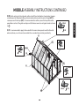
1
GRANDIO
G R E E N H O U S E S
2015 GRANDIO ASCENT 8x12, 8x16, 8x20, 8x24 KIT MANUAL
INCLUDES INSTRUCTIONS FOR BACK DOOR TRANSFORMATION
Grandio Ascent 8x24 Shown In Image
STOP
This manual is for
8x12, 8x16, 8x20 & 8x24.
GREENHOUSE USER MANUAL
© 2013 Grandio Greenhouses, Backyard Living Source Inc. All rights reserved
2015 Extendable Models
If building an 8x8 with
no extensions refer to
that manual.
GRANDIO
IMPORTANT! PLEASE READ BEFORE BEGINNING ASSEMBLY
G R E E N H O U S E S
Dear Valued Customer,
We would like to congratulate you on your new
Grandio Greenhouse purchase. We are confident
that you have made the right decision in choosing Grandio. Our greenhouses are made with
high quality aluminium and polycarbonate and
will last for many garden seasons to come.
Please take the time to carefully read this
instruction manual for an easier and more
enjoyable assembly experience.
Cheers!
Grandio Greenhouses
Before you begin, take time to complete this check list.
Take inventory of all parts using the parts list at the back of this manual on
pages 66-75. The base kit parts list is at the front on page 12 and 13. The back
door transformation kit parts list is on page 76.
Be cautious where you place the polycarbonate panels as they will burn grass
or plants if left on top of them in direct sunlight. Note that clear film side of
panels should always face the sun and white film side faces inside greenhouse. Panels may scratch easily so be careful what you clean them with.
Plan out when and where you are going to place the greenhouse, we recommend that you place it in an area that will receive direct sunlight and will be
protected from the wind as much as possible
It will take at least (2) people to put the greenhouse together.
Save this owner’s manual for future
reference and if you need our help.
CONTACT OUR CUSTOMER SERVICE
DEPARTMENT at:
1-866-448-8231
Hours: 8:30a.m.-5:00p.m. Monday through
Friday (Mountain Standard Time)
Backyard Living Source
9543 W. Emerald St., Suite 101
Boise, ID 83704
www.grandiogreenhouses.com
Before your build, make sure you are allowed to build it! Consult all building
codes, as well as City or Municipality ordinances and HOA’s, as you may need
a permit or documentation before you build.
Contact your insurance company to make sure your Grandio Greenhouse will
be covered on your policy.
Call your local utilities companies before digging.
Do not attempt to begin construction on a windy day.
Your greenhouse should be built on a flat level surface allowing for drainage.
Read this entire manual to get familiar with all pieces and parts prior to
beginning assembly. Follow the steps outlined in the order presented!
1
IMPORTANT! SAFETY INSTRUCTIONS
FAILURE TO FOLLOW THESE WARNINGS MAY RESULT IN SERIOUS INJURY OR
PROPERTY DAMAGE AND WILL VOID WARRANTY.
To ensure safety, do not attempt to assemble this product without following the instructions carefully. Check entire box and
inside all packing material for parts and/or additional instruction materials. Before beginning assembly, read the instructions and identify all parts using the hardware identifier and parts list on pages 67-76. Complete assembly and
proper usage are essential to reduce the risk of accident or injury when using your Grandio Greenhouse.
CAUTION: Do not leave polycarbonate panels laying on grass or leave in the sun or extreme heat, keep in a cool
dry place until they are to be installed!! (May cause burning to plants or grass if left directly on top of them, also may
damage panels due to the protective film adhering to panels.) Panels may scratch easily. Do Not use solvent cleaners.
• Each of the polycarbonate panels have a clear film side that should always face the sun, and a white film side which faces inside.
The clear side has a UV coating and we recommend marking a small “x” on a corner of each panel to determine which side has the
UV Coating as you cannot visually determine with your eye in the case of future disassembly.
• Due to shipping, the grooves of some of the aluminum profiles may be too small to insert into the polycarbonate sheet, you may
carefully use a screwdriver to pry the framework open so the polycarbonate sheet can be inserted smoothly.
• Do not use or store hot objects such as grills, blow torches, welding equipment, etc. in or near your greenhouse.
• Do not allow children or pets to play in greenhouse or in the set up area until assembly is complete.
• If using a ladder during assembly, use extreme caution.
• A clean level surface is essential to maintaining the solid integrity of the structure, Install the base correctly as described in
manual. Please anchor the greenhouse down to a firm and level base. If not properly installed warranty may be void.
NEEDED FOR ASSEMBLY
• Tape Measure
• 2 Step Ladders
• Level
• Work Gloves
• Carpenter Square
• Permanent Marker
• At Least 2 Adults
• Masking Tape
GRANDIO
• Safety Glasses
• Drill
• Silicone Caulk
• Folding Utility Table
2
TIP
When you see this icon
pay special attention to
the helpful tips we have provided that will
make installation more efficient.
GRANDIO
©
G R E E N H O U S E S
ASSEMBLY INSTRUCTION STEPS
PREPARE FOR ASSEMBLY
STEP ONE: BASE ASSEMBLY
STEP TWO: FRONT ASSEMBLY
STEP THREE: BACK ASSEMBLY
STEP FOUR: MIDDLE ASSEMBLY
STEP FIVE: EXTENSION ASSEMBLY
STEP SIX: INTERIOR SUPPORT ASSEMBLY
STEP SEVEN: DOOR ASSEMBLY
3
Introduction.............................................................................1
Safety Instructions.................................................................2
Prepare For Assembly...........................................................4
Box Configurations ...............................................................5
Diagrams of Assembled Grandio Ascent Sizes
8x8, 8x12, 8x16, 8x20, 8x24.........................6-10
Base Kit Assembly Information.......................................11
Base Kit Parts Lists........................................................12-13
8x12 Base Kit........................................................................14
8x16 Base Kit........................................................................15
8x20 Base Kit........................................................................16
8x24 Base Kit........................................................................17
Base Kit Assembly and Installation........................18-20
Front Assembly.............................................................21-26
Back Assembly..............................................................27-31
Middle Assembly.........................................................32-37
Extension Assembly...................................................38-44
8x20 and 8x24 Extension Assembly.....................45-49
Extension Assembly Continued.............................50-58
Interior Roof Supports.....................................................59
Door Assembly.............................................................60-65
GRA-ASC-8A Parts List...............................................66-68
GRA-ASC-8P Parts List......................................................69
GRA-ASC-4X Parts List................................................70-72
GRA-ASC-8XA Parts List.............................................73-74
GRA-ASC-8XP Parts List....................................................75
GRA-ASC-BD Parts List......................................................76
Warranty.................................................................................77
PREPARE FOR GREENHOUSE ASSEMBLY
IMPORTANT: BASE KIT ASSEMBLY &
GREENHOUSE PLACEMENT
Before assembling your new greenhouse, a proper
foundation must be prepared. A number of anchoring options are acceptable, based on wind and
ground conditions in your area.
8X12 GRANDIO ASCENT BARN STYLE
GREENHOUSE DIMENSIONS
The UV-Protected side is covered with clear film and
must face toward the sun. The side covered in white film
will always face the interior of the greenhouse. We
1
suggest you peel all film off completely prior to assem- BASE 3 /4”
bly and use a permanent marker to place a small “X” on
the lower right corner of each panel on the clear side
that faces the sun, each panel has a sticker labeling the
panel number and this side always faces the sun or
outward as well. DO NOT REMOVE LABELS UNTIL
YOU INSTALL PANELS. The “X” is suggested in case
you dis-assemble your greenhouse in the future so you
may identify which side has the UV coating. Always use
gloves when handling the polycarbonate panels as the
edges can be very sharp.
55 11/16”
8X
12
LE
FT
144”
SID
E
8X
12
42” R
O
DO
H
97.5” IDT
TW
ON
R
F
Sun
Transparent Clear Film
Polycarbonate
Panels
72 1/16”
*SEE BASE KIT ASSEMBLY SECTION FOR ALL
GREENHOUSE BASE DIMENSIONS ON PAGES 14-17.
Opal White Film
4
DOOR HEIGHT
IMPORTANT: POLYCARBONATE PANELS
1 3/4”
GUTTERS
93”
EAVE HEIGHT
Go to www.grandiogreenhouses.com for foundation ideas and tour our online learning center for
tips, tricks and videos for putting your greenhouse
together.
ROOF PEAK HEIGHT
Pre-read pages 11-20 for base kit assembly information.
EXTENSION KIT BOX CONFIGURATIONS
We recommend that you lay all of your boxes out as shown below for an organized assembly. Locate your greenhouse size and situate near
your assembly site. We suggest you lay the parts out on a tarp so you do not lose items in the grass or dirt near your building site.
*See the reference diagrams on pages 6-10 for more information about how the parts will go together and what makes up each section for
the assembly. If building a back door you will follow the instructions in the manual, the parts for the transformation are in box GRA-ASC-BD.
GRANDIO ASCENT 8X16
Ascent 8’x8’
GRA-ASC-8A
+
GRA-ASC-8P
Back
Back
Aluminum Extrusions,
Hardware Bag, 4’ Base
Extension, 1 Roof Vent,
2 Snow Load Extension
Supports, Polycarbonate Panels for 4’
Extension.
Front
Aluminum Extrusions,
Hardware Bag, Front,
Back and Doors.
GRA-ASC-4X
Ascent 8’ Extension
+
GRA-ASC-8P
Back
Aluminum Extrusions,
Hardware Bag, Front,
Back and Doors.
Front
Back
Aluminum Extrusions,
Hardware Bag, 8’ Base
Extension, 2 Roof
Vents, 2 Snow Load
Extension Supports.
GRA-BAS-8
Base kit & hardware
GRANDIO ASCENT 8X24
GRA-ASC-8A
GRA-ASC-8XA
Polycarbonate Panels
For The 8’ Extension
8x8 Base Kit
GRA-BAS-8
Base kit & hardware
5
Ascent 8’x8’
Ascent 8’ Extension
GRA-ASC-8XA
GRA-ASC-8XA
Aluminum Extrusions,
Hardware Bag, 8’ Base
Extension, 2 Roof
Vents, 2 Snow Load
Extension Supports.
Aluminum Extrusions,
Hardware Bag, 8’ Base
Extension, 2 Roof
Vents, 2 Snow Load
Extension Supports.
+
Polycarbonate Panels
GRA-ASC-8XP
GRA-ASC-8P
8x8 Base Kit
Polycarbonate Panels
For The 8’ Extension
Ascent 8’x8’
Ascent 8’ Extension
+
+
GRA-ASC-8XP
8x8 Base Kit
GRANDIO ASCENT 8X20
Aluminum Extrusions,
Hardware Bag, 4’ Base
Extension, 1 Roof Vent,
2 Snow Load Extension
Supports, Polycarbonate Panels for 4’
Extension.
Aluminum Extrusions,
Hardware Bag, Front,
Back and Doors.
Polycarbonate Panels
Base kit & hardware
GRA-ASC-4X
Aluminum Extrusions,
Hardware Bag, 8’ Base
Extension, 2 Roof
Vents, 2 Snow Load
Extension Supports.
Polycarbonate Panels
GRA-BAS-8
Ascent 4’ Extension
GRA-ASC-8A
GRA-ASC-8XA
GRA-ASC-8A
Aluminum Extrusions,
Hardware Bag, Front,
Back and Doors.
+
GRA-ASC-8P
Polycarbonate Panels
GRA-ASC-8XP
GRA-ASC-8P
Polycarbonate Panels
For The 8’ Extension
Polycarbonate Panels
For The 8’ Extension
8x8 Base Kit
GRA-BAS-8
Base kit & hardware
Front
Ascent 4’ Extension
Ascent 8’x8’
Ascent 8’ Extension
Front
GRANDIO ASCENT 8X12
BA-S1
606-WS
Y1
LEFT SIDE
610
L08C-X
606-WS
606-WS
610
Y6
L08C
606-WS
Y6
602B
Y1
L08B-X
Y2-2
L08B
Y4-2
Y4-1
Y2-1
601A-B
RIGHT SIDE
609
601B
609
610
602C
Y7
602B
601B
Y7
Y7
618
Y8
L28
Y2-1
L08D
603B
Y7
603C
603A
601B
L08A-X
601A-FL
Y1
606-WS
BA-S1
Y3-1 Y3-2
623A
622 Y5
623A
Y5 622
622-L
622-R
620
620
Y5
Y5
623B
623B
FRONT
6
610
Y6
L08C
618
Y8
L21
Y2-2
L08D
603B
604-R
L28
Y7
L08A-X
601A-FR
Y1
BA-S2
Y6
602A
615
601B
L08C-X
606-WS
602A
602B
607
604-L
LEFT SIDE
602D
Y1
603B
615
Y9
606-WS
602D
Y1
602B
602A
606-WS
603B
609
Y7
L08A
L08B-X
602B
606-WS 603B/616
Y6
602A
606-WS
L08C-X
609
Y6
602A
BA-S2
601A-B
DIAGRAM SHOWS THE ASSEMBLED
(8’x8’ BASIC CONFIGURATION)
(GRA-ASC-8A & GRA-ASC-8P & GRA-BAS-8)
8x8 ASCENT KIT INCLUDES, FRONT,
BACK, BASE AND SIDES.
Y9
602B
Y6
Y6
606-WS
603B/616 606-WS
602A
606-WS
L08C-X
RIGHT SIDE
606-WS
619
Outside View
(4’ Extensions Side) 4X Ascent Side
602A
7
602B
Y6
In boxes GRA-ASC-8A and GRA-ASC-8P,
the base for 8x8 is all in GRA-BAS-8.
609
606-WS
Y1
607
Y5
623B
Y5
623B
FRONT
620
622-R
622-L
620
623A
Y5 622
L21
615
619
606-WS
Y1
604-R
Y2-2
L08D
603B
601B
603C
623A
622 Y5
Y3-1 Y3-2
607
609
615
Y2-1
Y4-1
601B
L08B-X
606-WS
Y1
603B
602D
Y1
606-WS
In boxes GRA-ASC-8A and GRA-ASC-8P,
the base for 8x8 is all in GRA-BAS-8.
604-L
L08D
603B
Y2-1
601B
603A
615
601B
602C
Y4-2
L08B
Y2-2
BA-S1
Y7
618
Y8
Y7
Y7
Y7
Y7
L08A-X
601A-FL
Y9
603B/616
Y6
602A
LEFT SIDE
602B
L08C
602B
609
602B
L08C
602B
602A
Y6
Y6
610
Y6
Y6
609
603B
L08B-X
602D
Y1
606-WS
L08A
DIAGRAM SHOWS THE ASSEMBLED
8X12 GRANDIO ASCENT
THE BOX CONFIGURATION IS AN ASCENT
8X8 PLUS A 4 FOOT EXTENSION KIT
606-WS
L08C-X
606-WS
606-WS
BA-S2
602A
L08M-X
606-WS
606-WS
BA-S2
602A
L08C-X
606-WS
610
610
601A-B
606-WS
Y1
BA-S1
BACK
In boxes GRA-ASC-8A and GRA-ASC-8P,
the base for 8x8 is all in GRA-BAS-8.
Outside View
8x8 Ascent Side
L08C
609
602A
Y6
Y6
606-WS
606-WS
L08C-X
BA-S4
602A
602A
L08C-X
606-WS
RIGHT SIDE
602A
606-WS
606-WS
BA-S2
L08M-X
606-WS
603B/616
Y6
Y6
610
Y6
603B/616
Y6
610
In boxes GRA-ASC-8A and GRA-ASC-8P,
the base for 8x8 is all in GRA-BAS-8.
602B
Y9
602B
L08C
602B
609
602B
Y9
602B
L08A-X
601A-FR
Y7
618
Y8
Y7
Y7
618
Y8
Y7
610
601A-B
(4’ Extension Side) (GRA-ASC-4X)
Ascent 4’ Side Extension
Includes Base
(8’x8’ Original Kit) (GRA-ASC-8A & GRA-ASC-8P & GRA-BAS-8)
8x8 Ascent Includes Front, Back, Base, and Sides
(8’ Extension Side) 8X Ascent Side
8
Y9
602B
603B/616
Y6
602A
Y6
In boxes GRA-ASC-8A and GRA-ASC-8P,
the base for 8x8 is all in GRA-BAS-8.
LEFT SIDE
606-WS
L08C-X
602B
L08C
602A
Y6
602B
601B
Y2-1
601B
603A
609
610
Y2-2
601A-B
L08B-X
BA-S1
606-WS
617
602C
Y4-2
L08B
603B
602D
Y1
606-WS
Y4-1
601B
Y5
623B
Y5
623B
FRONT
620
622-R
L21
615
615
619
606-WS
Y1
604-R
Y2-2
L08D
603B
601B
609
610
Y2-1
603C
623A
Y5 622
620
622-L
623A
622 Y5
Y3-1 Y3-2
617
L08B-X
603B
601A-B
606-WS
Y1
602D
Y1
606-WS
L08A
In boxes GRA-ASC-8A and GRA-ASC-8P,
the base for 8x8 is all in GRA-BAS-8.
Y1
604-L
L08D
603B
615
615
L08A-X
601A-FL
Y7
618
Y8
Y7
Y7
Y7
618
Y8
Y7
Y7
606-WS
Y1
BA-S1
DIAGRAM SHOWS THE ASSEMBLED
8X16 GRANDIO ASCENT
THE BOX CONFIGURATION IS AN ASCENT 8X8
PLUS AN 8 FOOT EXTENSION KIT
606-WS
606-WS
BA-S2
602A
Y6
609
602B
Y6
610
Y9
603B/616
Y6
602A
L08C
602B
602A
Y6
Y6
609
602B
L08M-X
606-WS
606-WS
606-WS
606-WS
BA-S2
602A
L08C-X
606-WS
610
BACK
In boxes GRA-ASC-8A and GRA-ASC-8P,
the base for 8x8 is all in GRA-BAS-8.
Outside View
8x8 Ascent Side
L08A-X
601A-FR
Y7
618
Y8
Y7
Y7
Y7
618
Y8
Y7
Y7
602A
602A
602A
602A
602A
L08C-X
606-WS
606-WS
606-WS
BA-S2
RIGHT SIDE
Y6
Y6
606-WS
606-WS
L08M-X
606-WS
602A
603B/616
Y6
Y6
610
Y6
Y6
606-WS
BA-S2
L08C-X
606-WS
603B/616
Y6
Y6
610
In boxes GRA-ASC-8A and GRA-ASC-8P,
the base for 8x8 is all in GRA-BAS-8.
602B
Y9
602B
L08C
602B
609
602B
Y9
602B
L08C
602B
609
(8’ Extension Side) (GRA-ASC-8XA & GRA-ASC-8XP)
Ascent 8’ Side Extension includes Base
(8’x8’ Original Kit) (GRA-ASC-8A & GRA-ASC-8P & GRA-BAS-8)
8x8 Ascent Includes Front, Back, Base, and Sides
(4’ Extensions Side) 4X Ascent Side
(8’ Extension Side) 8X Ascent Side
602A
9
602B
Y9
602B
603B/616
Y6
602A
Y6
L08C
602A
Y6
In boxes GRA-ASC-8A and GRA-ASC-8P,
the base for 8x8 is all in GRA-BAS-8.
LEFT SIDE
606-WS
L08C-X
606-WS
606-WS
BA-S2
602B
BA-S1
606-WS
Y1
604-L
607
602C
Y4-2
622-R
622-L
L08A-X
623B
FRONT
L08A-X
623B
620
Y5
623A
Y5 622
620
Y5
609
610
Y2-1
615
618
Y8
Y7
Y7
Y7
618
Y8
Y7
Y7
L08C
602B
609
Y9
602B
L08C
609
602A
602A
602A
602A
602A
602A
602A
L08C-X
606-WS
606-WS
606-WS
BA-S2
606-WS
AZ1
L08M-X
606-WS
606-WS
RIGHT SIDE
Y6
Y6
603B/616
Y6
Y6
610
Y6
Y6
606-WS
BA-S2
L08M-X
606-WS
AZ1
606-WS
606-WS
L08C-X
BA-S4
602A
603B/616
Y6
Y6
610
Y6
603B/616
Y6
610
In boxes GRA-ASC-8A and GRA-ASC-8P,
the base for 8x8 is all in GRA-BAS-8.
602B
Y9
602B
L08C
602B
609
602B
Y9
602B
602B
618
Y8
Y7
Y7
601A-FR
615
615
619
606-WS
Y1
604-R
Y2-2
L08D
603B
601B
L21
603C
623A
622 Y5
Y3-1 Y3-2
607
607
Y4-1
601A-B
In boxes GRA-ASC-8A and GRA-ASC-8P,
the base for 8x8 is all in GRA-BAS-8.
Y2-1
601B
603A
609
610
L08D
603B
615
615
601A-FL
Y7
618
Y8
Y7
Y7
Y7
618
Y8
Y7
Y7
Y7
Y7
L08B
601A-B
Y2-2
L08B-X
603B
602D
Y1
DIAGRAM SHOWS THE ASSEMBLED
8X20 GRANDIO ASCENT
THE BOX CONFIGURATION IS AN ELITE 8X8
PLUS AN 8 FOOT AND A 4 FOOT EXTENSION KIT
602A
Y6
610
602B
Y6
609
Y9
603B/616
Y6
602A
L08M-X
606-WS
AZ1
606-WS
606-WS
602B
L08C
602B
609
602B
L08C
602B
602A
Y6
Y6
610
Y6
Y6
603B
602D
Y1
606-WS
Y1
606-WS
L08A
606-WS
L08B-X
606-WS
Y1
BA-S1
Outside View
606-WS
BA-S2
602A
L08M-X
606-WS
AZ1
606-WS
BA-S2
602A
L08C-X
606-WS
610
609
BACK
In boxes GRA-ASC-8A and GRA-ASC-8P,
the base for 8x8 is all in GRA-BAS-8.
(8’ Extension Side) (GRA-ASC-8XA & GRA-ASC-8XP)
Ascent 8’ Side Extension includes Base
8x8 Ascent Side
(4’ Extension Side) (GRA-ASC-4X)
Ascent 4’ Side Extension
Includes Base
(8’x8’ Original Kit) (GRA-ASC-8A & GRA-ASC-8P & GRA-BAS-8)
8x8 Ascent Includes Front, Back, Base, and Sides
(8’ Extension Side) 8X Ascent Side
(8’ Extension Side) 8X Ascent Side
10
602B
Y9
602B
603B/616
Y6
602A
Y6
L08C
602B
609
602B
602A
Y6
Y6
610
Y6
Y9
602B
LEFT SIDE
606-WS
L08C-X
606-WS
606-WS
602A
L08M-X
603B/616
Y6
602A
Y6
L08C
602B
615
615
606-WS
Y1
604-L
L08D
603B
Y2-1
601B
603A
609
610
BA-S1
601A-FL
Y7
618
Y8
Y7
Y7
Y7
618
Y8
Y7
Y7
615
601A-B
Y2-2
L08B-X
606-WS
Y1
607
602C
Y4-2
L08B
603B
602D
Y1
606-WS
L08A-X
623B
FRONT
L08A-X
623B
620
Y5
622-R
622-L
620
Y5
623A
Y5 622
618
Y8
Y7
Y7
Y7
618
Y8
Y7
Y7
Y7
618
Y8
Y7
Y7
Y7
601A-FR
615
615
615
619
606-WS
Y1
604-R
Y2-2
L08D
603B
601B
L21
609
610
Y2-1
601A-B
L08B-X
606-WS
Y1
603C
623A
622 Y5
Y3-1 Y3-2
607
607
Y4-1
603B
602D
Y1
606-WS
L08A
BACK
DIAGRAM SHOWS THE ASSEMBLED
8X24 GRANDIO ASCENT
THE BOX CONFIGURATION IS AN ASCENT
8X8 PLUS (2) 8 FOOT EXTENSION KITS
BA-S2
606-WS
606-WS
606-WS
602A
602A
Y6
Y7
618
Y8
Y7
Y7
BA-S1
Outside View
606-WS
BA-S2
606-WS
610
602B
Y6
609
Y9
603B/616
Y6
602A
L08C
602B
602B
Y6
Y6
609
602A
606-WS
L08M-x
606-WS
606-WS
BA-S2
602A
L08C-X
606-WS
610
602A
602A
602A
602A
602A
602A
602A
602A
602A
602A
Y6
Y6
602A
603B/616
Y6
Y6
610
Y6
Y6
603B/616
Y6
Y6
610
Y6
Y6
L08C-X
606-WS
606-WS
606-WS
BA-S2
606-WS
AZ1
L08C-X
606-WS
606-WS
606-WS
BA-S2
606-WS
AZ1
L08M-X
606-WS
606-WS
606-WS
BA-S2
L08C-X
606-WS
603B/616
Y6
Y6
610
RIGHT SIDE
602B
Y9
602B
L08C
602B
609
602B
602B
Y9
602B
L08C
602B
609
602B
602B
Y9
602B
L08C
602B
609
(8’ Extension Side) (GRA-ASC-8XA & GRA-ASC-8XP)
Ascent 8’ Side Extension includes Base
8x8 Ascent Side
(8’ Extension Side) (GRA-ASC-8XA & GRA-ASC-8XP)
Ascent 8’ Side Extension includes Base
(8’x8’ Original Kit) (GRA-ASC-8A & GRA-ASC-8P & GRA-BAS-8)
8x8 Ascent Includes Front, Back, Base, and Sides
BASE KIT ASSEMBLY INSTRUCTIONS
Pre-Plan The Placement Of Your Structure
Allow enough room to get a wheel barrow in and around your structure.
Be sure the orientation will allow for proper drainage in and around your greenhouse.
It is recommended that you place your greenhouse in an area of your property that receives the most sunlight but is also somewhat protected
by trees, fencing or your home for wind protection and also to keep the temperature up during early spring and late fall.
The best placement depends on the features of your property, it is suggested in most scenarios to have your greenhouse face South on its
broadest side and to have the door face East or West depending on typical wind directions in your area. Do not worry if your orientation will
not allow for the placement to be as suggested, as a greenhouse that is facing North is better than no greenhouse at all.
Avoid building your greenhouse at the base of a slope as these are often frost pockets where cold air collects, this will not be good for your
greenhouse in keeping the temperature up inside.
Extreme Wind Conditions: If you live in a windy location there is no way to build a 100% storm safe greenhouse, but there are a number
of things you can do to minimize the chance of damage. Ensure that the base is level and square, be sure all panels are tightly in place and that
all aluminum extrusions are tight. The main problem is usually that wind gets into the greenhouse and the pressure pushes a panel out and
then the force of the wind on the interior causes more damage. It is best if you are expecting an extreme weather event that you disable any
auto roof vents and make sure all doors and windows are closed and locked shut. Also you may need to build a wind break for extreme condition areas where wind is constant and extreme.
See our website GrandioGreenhouses.com for Extreme Weather Anchoring Kits and Moisture Control Kits to aid in protecting your greenhouse in the event of harsh weather conditions prior to beginning assembly.
It is ideal for your greenhouse to have water, electricity and even gas plumbed into place before construction. This will make watering plants
and keeping the temperature and air circulation to the max efficiency.
See pages 19 and 20 for installation methods below
For Cement Base Installation: We suggest you use wedge style concrete anchoring bolts to secure your structure.
For Deck Base Installation: We recommend you use a set of anchoring bolts to secure your structure.
For Earth Installation: We recommend you use the anchoring system provided and bury corner posts into the ground and seal into place
with quickrete.
11
BASE KIT PARTS LIST
GRAPHIC
PART NAME
SIZE/LOCATION
QUANTITY
BA-S1
97 3/8 in / 2474 mm
2
BA-S2
94/4 in / 2394 mm
BA-C3
GRAPHIC
SIZE/LOCATION
QUANTITY
BA-S5
46 3/4 in / 1187 mm
1
2
BA-S6
46 3/4 in / 1187 mm
1
5 7/16 in 138 mm
4
BA-C4
8 7/16 in / 214 mm
2
BA-A1
9 13/16 in / 250 mm
4
BA-A1
9 13 /16 in / 250 mm
2
BA-S03
M6*14
28
BA-S10
1/2 x 3/4
2
BA-M03
NUT
28
BA-S03
M6*14
16
W05
CLIPS
9
BA-M03
NUT
16
12
PART NAME
PARTS LIST FOR BASE KIT
(GRA-BAS-4X) BASE AND ACCESSORY PACKING LIST
PARTS WILL BE FOUND IN (GRA-ASC-4X) BOX
(GRA-BAS-8) BASE AND ACCESSORY PACKING
LIST PARTS WILL BE FOUND IN (GRA-BAS-8) BOX
BASE KIT PARTS LIST
(GRA-BAS-8X) BASE AND ACCESSORY PACKING LIST
PARTS WILL BE FOUND IN (GRA-ASC-8XA) BOX
GRAPHIC
PART NAME
PARTS LIST FOR BASE KIT
SIZE/LOCATION
QUANTITY
BA-S3
93 7/16 in / 2374 mm
1
BA-S4
93 7/16 in / 2374 mm
1
BA-C4
8 7/16 in /214 mm
2
BA-A1
9 13/16 in / 250 mm
2
BA-S10
1/2 X 3/4
2
BA-S03
M6*14
16
BA-M03
NUT
16
13
8x12 BASE KIT ASSEMBLY INSTRUCTIONS
(GRA-BAS-8) AND (GRA-ASC-4X)
1.1 Layout all base kit pieces to prepare for assembly. Note that one BA-S1 will be at the front
BA-S5
and one BA-S1 will be at the back and the BA-S2’s will be on the sides attaching to the front
BA-S1. The BA-S5 and BA-S6 will attach to the back BA-S1, See diagram .
1.2 Attach the BA-S2 to the BA-S5 with the BA-C4 using the BA-S03 and BA-M03.
See
. Repeat for other side connecting the BA-S6 and the BA-S2.
Go to page 18 for the next step.
BA-S2
BA-C4
BA-S03
BA-M03
BA-C3
BA-S1
BA-C3
BA-A1
BA-S5
14
4”
BA-S10
BA-C4
BA-S6
BA-A1
BA-A1
BA-S2
BA-S10
BA-C4
BA-S2
BA-S1
BA-C3
Note that the holes for
T I P screws on the base kit
sides have about a 2 foot gap between
each, so be sure base kit extensions
are assembled properly. See
.
BA-C3
BA-A1
GRANDIO
.5”
97
BA-A1
14
STEP ONE
BA-A1
8x16 BASE KIT ASSEMBLY INSTRUCTIONS
(GRA-BAS-8) AND (GRA-ASC-8XA)
1.3 Layout all base kit pieces to prepare for assembly. Note that one BA-S1 will be at the front
BA-S3
and one BA-S1 will be at the back and the BA-S2’s will be on the sides attaching to the front
BA-S1. The BA-S3 and BA-S4 will attach to the back BA-S1 See diagram
.
1.4 Attach the BA-S2 to the BA-S3 with the BA-C4 using the BA-S03 and BA-M03.
See
. Repeat for other side connecting the BA-S4 and the BA-S2.
Go to page 18 for the next step.
BA-S2
BA-C4
BA-S03
BA-M03
BA-C3
BA-S1
BA-A1
BA-C3
BA-S3
BA-S4
.5”
BA-A1
BA-A1
BA-A1
STEP ONE
191
BA-S10
BA-C4
BA-S2
BA-C3
BA-S2
BA-S10
BA-C4
Note that the holes for
T I P screws on the base kit
sides have about a 2 foot gap between
each, so be sure base kit extensions
are assembled properly. See
.
BA-S1
BA-A1
BA-C3
BA-A1
15
5”
.
97
GRANDIO
8x20 BASE KIT ASSEMBLY INSTRUCTIONS
(GRA-BAS-8) AND (GRA-ASC-8XA) AND (GRA-ASC-4X)
1.5 Layout all base kit pieces to prepare for assembly. Note that one BA-S1 will be at the front
and one BA-S1 will be at the back and the BA-S2’s will be on the sides attaching to the front
BA-S1. The BA-S5 and BA-S6 will attach to the back BA-S1, See diagram
.
1.6 Attach the BA-S2 to the BA-S3 with the BA-C4 using the BA-S03 and BA-M03.
See
. Repeat for other side connecting the BA-S4 and the BA-S2, then BA-S3 to BA-S5
and BA-S4 to BA-S6.
Go to page 18 for the next step.
BA-S5
BA-S2
BA-C4
BA-S03
BA-M03
BA-C3
BA-S6
BA-S5
BA-A1 BA-S10
BA-C4
BA-A1
238
.5”
BA-S3
BA-S10
BA-C4
BA-A1
BA-S10
BA-C4
BA-A1
BA-S4
BA-A1
BA-S2
BA-S2
Note that the holes for
T I P screws on the base kit
sides have about a 2 foot gap between
each, so be sure base kit extensions
are assembled properly. See
.
GRANDIO
BA-S10
BA-C4
BA-A1
BA-C3
BA-C3
BA-S1F
5”
.
97
BA-A1
16
STEP ONE
BA-S1B
BA-C3
8x24 BASE KIT ASSEMBLY INSTRUCTIONS
(GRA-BAS-8) AND (GRA-ASC-8XA) AND (GRA-ASC-8XA)
1.7 Layout all base kit pieces to prepare for assembly. Note that one BA-S1 will be at the front
and BA-S1 will be at the back and the BA-S2’s will be on the sides attaching to the front BA-S1.
The BA-S3 and BA-S4 will attach to the back BA-S1. The BA-S3 will attach to the other BA-S3
and BA-S4 will attach to the other BA-S4 See diagram
.
1.8 Attach the BA-S2 to the BA-S3 with the BA-C4 using the BA-S03 and BA-M03.
See
. Repeat for other side connecting the BA-S4 and the BA-S2, and then the BA-S3
to the BA-S3, and then the BA-S4 to the BA-S4.
Go to page 18 for the next step.
BA-S3
BA-S2
BA-C4
BA-S03
BA-M03
BA-C3
BA-S1
BA-C3
BA-A1
BA-S3
BA-S4
BA-S10
BA-C4
BA-A1
286
”
BA-A1
BA-A1
BA-S10
BA-C4
BA-S3
BA-S4
BA-S10
BA-C4
BA-A1
BA-S2
STEP ONE
BA-S2
Note that the holes for
T I P screws on the base kit
sides have about a 2 foot gap between
each, so be sure base kit extensions
are assembled properly. See
.
BA-C3
GRANDIO
BA-A1
17
BA-S10
BA-C4
BA-C3
BA-S1
”
.5
97
BA-A1
BASE KIT ASSEMBLY INSTRUCTIONS
1.9 Slide the BA-C3 into the BA-S1, slide the BA-S2 into the BA-C3, align the holes and push together to an even and tight
position and use the BA-S03 Bolt and BA-M03 Collard Nut combo, tighten the collard nut on the inside of the base kit using the
10mm wrench. Repeat this process on all corners. See
and
.
Note: BA-S1 will be the front and back, while the BA-S2’ s will be the sides of your greenhouse base.
1.10 For Ground Installation only Insert the BA-S03 and the BA-A1 into the holes at the bottom side of the corners
of the base, the nut will be tightened on the inside of base. You will install the BA-A1 and the BA-S10 in the middle
where the extensions meet see
. If you are mounting your base kit to a flat mount surface like a deck or cement pad
discard the BA-S10 and BA-A1, you will need to purchase a fastener for your installation surface.
BA-S03
FRO
BA-S1
NT
BA-S2
BA-S1
E
SID
BA-C3
BA-S03
BA-S03
ML01
BA-S03
BA-M03 Collared Nut
BA-C3
BA-S3
BA-S2
BA-A1
BA-M03 Collared Nut
BA-A1
BA-C4
BA-S03
BA-M03
BA-S10
18
STEP ONE
BA-S2
BASE KIT GROUND INSTALLATION
**BASE MUST BE LEVEL & SQUARE,
FOUNDATION MUST BE PROPERLY ANCHORED PRIOR TO GREENHOUSE ASSEMBLY
1.11 BA-A1 must be buried in ground. See
.
Dig holes to bury the BA-A1’s, you determine size and depth for your location.
We recommend you use: Quikrete fast setting concrete to anchor base. Follow the directions on the package.
Outdoor
Ground
Assembly
BA-S2
Make sure base is squared
and level before setting
anchor into concrete. Use a measuring tape
to ensure all corners are the same. Use level
on all four sides.
BA-S1
GRANDIO
STEP ONE
TIP
BA-S03
BA-A1
19
BA-A1 * Must be inserted
into the ground, and secured
with concrete.
BASE KIT DECK INSTALLATION
**BASE MUST BE LEVEL & SQUARE,
FOUNDATION MUST BE PROPERLY ANCHORED PRIOR TO GREENHOUSE ASSEMBLY
1.12 Holes are present in base kit for anchoring bolts see
and
.
You determine and acquire proper fastener prior to installation for your surface.
Discard the BA-A1 and BA-S10 for deck or concrete slab installation.
Use lag bolt
or concrete anchors
to attach base.
(Fasteners not included).
BA-S1
BA-S2
BA-S6
Deck or
Patio
Assembly
BA-S2
BA-C3
HOLE FOR ANCHOR
BOLT OR SCREW.
B
BA-C4
BA-S03
BA-M03
Use an appropriate fastener
to attach to your surface
through these access holes.
If surface is uneven you may want
to purchase large washers that
will fit under the base and allow
fasteners to go through to use as
a shim for leveling the base kit.
Make sure base is squared
and level before setting
anchors. Use a measuring tape to ensure all
corners are the same. Use level on all four
sides.
TIP
20
STEP ONE
GRANDIO
FRONT FRAME ASSEMBLY
ALWAYS ASSEMBLE FRONT HORIZONTAL
This picture shows the inside view of front section fully assembled.
All parts for this section will be found in boxes GRA-ASC-8A and GRA-ASC-8P.
We recommend that you assemble the front wall on a tarp.
* If you purchased the Back Door Transformation kit you will repeat this section for your
back wall using parts found in GRA-ASC-BD box.
If you want to purchase the Back Door Transformation kit call 1-866-448-8231.
W01
603C
601B
W02T
Y3-2 Y3-1
603A
W02
601B
W02T
Y2-1
L08D / 603B
STEP TWO
TIP
W04
Y2-2
Y1
We recommend watching
our how to assembly videos
with tricks and tips for easier assembly and
installation of your Grandio Greenhouse at:
www.grandiogreenhouses.com
GRANDIO
L08D / 603B
Y1
604-R
604-L
L08A-X
L08A-X
601A-FR
606-WS
601A-FL
Inside View
606-WS
619
21
W02
Lay flat on ground to
assemble the front frame of
your greenhouse. If possible try to find a
shady area protected from the wind. Panels
can burn grass and plants if in direct light.
GRANDIO
TIP
BOLT INSTALLATION TIP:
Locate all nuts and bolts, pre
thread and place in the groove of the
extrusion to make installation easier. Move
up or down for exact placement.
GRANDIO
TIP
FRONT FRAME ASSEMBLY CONTINUED
ALWAYS ASSEMBLE FRONT HORIZONTAL
2.1 Use W01 bracket to attach the (2) 601B’s
together with the 603C, secure parts with the S05
fasteners provided as shown in
. Pre thread W01
fasteners with S05 for ease of installation, only turn a
few times. Screw heads will remain outside channel.
2.2 Insert Y3-1 and Y3-2 window panels as shown
in
.
S05
S04
ML01
W01
601B
601B
603A
2.3 Attach 603C and 603A with W04 and
S04/ML01 fasteners as shown in
603C
W04
S04/ML01
W02T
.
2.4 Attach W02T to 601B and 603A with the
603C
S04/ML01 fasteners as shown in
, leave a bit
loose to ease installation of next step.
601B
603A
Inside View
IMPORTANT: POLYCARBONATE PANELS
IMPORTANT: Use only S05 Screws, other screws may damage frame.
W01
W04
601B
603C
W02T
Y3-2
Sun
Transparent Clear Film
Polycarbonate
Panels
Inside View
601B
W02T
Y3-1
603A
Opal White Film
22
STEP TWO
The UV-Protected side is covered with clear film and must face
toward the sun. The side covered in white film will always face
the interior of the greenhouse. We suggest you peel all film off
completely prior to assembly and use a permanent marker to
place a small “X” on the lower right corner of each panel on the
clear side that faces the sun, each panel has a sticker labeling
the panel number and this side always faces the sun or
outward as well. DO NOT REMOVE LABELS UNTIL YOU
INSTALL PANELS. The “X” is suggested in case you
dis-assemble your greenhouse in the future so you may
identify which side has the UV coating. Always use gloves when
handling the polycarbonate panels as the edges can be very
sharp.
FRONT FRAME ASSEMBLY CONTINUED
ALWAYS ASSEMBLE FRONT HORIZONTAL
2.5 View diagrams and attach the (2) 604‘s and (2)
601A’s to the 619 with the S04/ML01 nut and bolt
combos. Note the orientation of the 601A-FR and
601A-FL and the holes that should be at the top of the
piece and face to the front, see the diagram to the right.
NOTE HOLES
ON 601A SHOULD
FACE FRONT OF
GREENHOUSE
604-R
604-L
OUTSIDE
INSIDE
shows where the corner pieces attach to 619.
OUTSIDE
601A-FL
OUTSIDE
601A-FR
shows where the door frame attaches to the 619.
*If assemblling the back door you will need to drill 1/4”
holes in 601-B’s to match the front wall, these holes
should face the ground during assembly.
INSIDE
INSIDE
619
OUTSIDE
INSIDE
Make sure the hole on the
T I P 601A-FL and 601A-FR
face to the front of greenhouse for future
install of the L21 and L28 bracket that
holds the door header in place.
GRANDIO
Inside View
TIP: If necessary you may use a screwdriver to wedge behind the
bolt head. This prevents bolt from falling into the track.
BOLT INSTALLATION TIP:
Locate all nuts and bolts, pre
thread and place in the groove of the
extrusion to make installation easier. Move
up or down for exact placement.
STEP TWO
GRANDIO
TIP
A
601A-FR
619
ML01
604-R
ML01
S04
INSIDE DOOR FRAME
S04
23
INSIDE
619
Inside View
FRONT FRAME ASSEMBLY CONTINUED
ALWAYS ASSEMBLE FRONT HORIZONTAL
2.6 Attach 606-WS to 619, this will hold the polycar-
bonate panels in place. If it seems too tight slide fingers
or nut driver along edges, gently stretching the 606-WS
to allow room for panels to fit .
Polycarbonate panel
OUTSIDE
606
619
2.7 Insert Y1 polycarbonate panels into place, make sure
Y1’s slide completely into 606-WS as shown in
.
2.8 Set (2) 603B’s atop the Y1 panels, then attach (2)
Y2-2
L08D’s to the 603B’s, 601A’s and 604’s using
S04/ML01 fasteners, make sure it is snug with the tops
of the Y1 panels, then tighten fasteners. See
and
.
L08D
2.9 Insert the Y2-2 and Y2-1 polycarbonate panels into
604-R
604-L
L08D
603B
603B
the track of the 603B.
601A-FR
606-WS
601A-FL
Y1
A
Y1
619
606-WS
A
Inside View
603B
601A-FR 604-R
L08D
GRANDIO
S04/
ML01
TIP
604A-R
Polycarbonate
Panel
24
Transparent Clear Film
Outside Greenhouse
Opal White Film
Inside Greenhouse
Sun
STEP TWO
L08D
603B
601A-FR
Y2-1
FRONT FRAME ASSEMBLY CONTINUED
ALWAYS ASSEMBLE FRONT HORIZONTAL
2.10 Move roof and front section together and align the WG02’s into the 601A’s, and align the S04/ML01’s on the W02T’s into
the 604’s. Insure a snug fit between the W02T’s, 601B’s and 601A’s and then tighten the S05 screws as shown in
. Tighten
the W02T’s with the S04 /ML01 nut and bolt as shown in
.
601B
W02
S05
603C
601A-FR
601B
Y3-2
STEP TWO
W02T
601B
FAT END
DOWN
603A
S04
ML01
S05
W02T
W02
Y2-2
FAT END
DOWN
Y2-1
L08D
W02T
W02
Y3-1
W02
603A
601B
601B
L08D
601A-FR
604-R
604-L
601A-FL
604-R
Y-1
Y-1
25
FAT END
FRONT FRAME ASSEMBLY CONTINUED
ALWAYS ASSEMBLE FRONT HORIZONTAL
2.11 Attach the (2) L08A-X ‘s to 601A’s and 604’s.
See
and
.
2.12 To square front section loosen S04/ML01 attached to the tops of the (2)
L08A-X’s, square the frame with carpenter square or use a measuring tape to
make sure corner measurements are the same, tighten L08X’s to hold squareness, L08A-X should be attached 1” up from bottom bolt see .
L08A-X
603C
601B
S04/ML01
W02T
Y3-1
W02T
603A
604-R
W02
L08A-X
Y3-2
601B
Y2-1
Y2-2
L08D
619
Y1
Use measuring tape to
measure from corner to
corner to assure square.
604-R
ML01
S04
L08D
Y1
604-L
L08A-X
L08A-X
601A-FL
601A-FR
Set front aside in a shaded
area, do not lay on grass,
prolonged sunlight through the polycarbonate panels will burn if placed directly on top
of plants during the intense sun of the day.
W02
GRANDIO
TIP
606-WS
606-WS
619
26
STEP TWO
601A-FR
BACK ASSEMBLY INSTRUCTIONS
ALWAYS ASSEMBLE BACK HORIZONTAL
This image shows the inside view of the back wall assembly.
All parts for back assembly will be found in box GRA-ASC-8A and GRA-ASC-8P.
We recommend that you assemble the back wall on a tarp.
* If you are using the Back Door Transformation Kit you will skip this section.
W01
GRANDIO
TIP
STEP THREE
Polycarbonate
Panel
Transparent Clear Film
Outside Greenhouse
Sun
Opal White Film
Inside Greenhouse
Make sure the UV coated
side of the panel faces
outward as indicated on the panels. Avoid
placing the polycarbonate panels in the sun
or near plants until fully assembled.
GRANDIO
TIP
BOLT INSTALLATION TIP:
Locate all nuts and bolts, pre
thread and place in the groove of the
extrusion to make installation easier. Move
up or down for exact placement.
601B
601B
W04-1
W04-1
Inside View
Y5-2
W02
L08B
Y2-2
603B
Y5-1
603B
603B
Y2
GRANDIO
TIP
602D
L08B-X
601A-B
606-WS
27
Y2-1
W02
603B
Y1
602D
602C
Y4
Y4
L08A
L08B-X
601A-B
606-WS
BACK CONTINUED
ALWAYS ASSEMBLE BACK HORIZONTAL
3.1 Prethread all S05 Screws into the W01 and
W02’s, only turn a few times, see
.
FAT
END
3.2 Use W01 bracket to attach the (2) 601B’s
.
WG02
Attach (2) W02’s to the (2) 601B’s as shown in
diagram
.
W01
601B
3.3 Attach (2) 601A-B’s to L08A using S04/ML01
fastener as shown in diagram
WG01
WG02
601B
.
Attach (2) 602D’s to L08A using S04/ML01 fasteners as shown in diagram
.
W02
W02
S05
Attach 602C to L08A using S04/ML01 fastener as
shown in diagram
.
601B
STEP THREE
together as shown in diagram
FAT
END
W01
601B
601B
W02
FAT END
DOWN
Inside View
601A-B
602D
602C
602D
602D
601A-B
601A-B
L08A
602C
L08A
ML01
S04
ML01
INSIDE
INSIDE
28
L08A
L08A
S04
BACK CONTINUED
ALWAYS ASSEMBLE BACK HORIZONTAL
3.4 Attach (4) 606-WS’s to L08A as shown in diagram
Insert the Y1 polycarbonate panels into the grooves of
601A-B’s, 602D’s and 602C. Make sure Y1 panels are
inserted into 606-WS as shown in
.
.
Y4-2
3.5 Set (4) 603B’s on top of the Y1’s that are now in
place. Attach L08B to (2) 601A-B’s, 602D’s and
the 602C with S04/ML01 fasteners as shown in
diagram
,
and , . Pre thread all fasteners
into assigned channels and align with L08B for
ease of installation.
Y2-2
STEP THREE
603B
603B
603B
Y2-1
603B
L08B
3.6 Insert the Y2-1 , Y2-2, Y4-1 and Y4-2 polycarbonate panels into place as shown in the
diagram to the right.
Y4-1
601A-B
Y1
Y1
602D
602C
Y1
Y1
601A-B
602D
L08A
606-WS
Inside View
Polycarbonate Panel
606-WS
L08A
603C
601A-B
L08B
L08B
603B
603B
603B
L08B
ML01
602C
S04
29
602D
L08B
602C
BACK CONTINUED
ALWAYS ASSEMBLE BACK HORIZONTAL
3.7 Attach the roof to the back wall use W01 fastener to 602C and the (2) W02’s
to the (2) 601A-B’s using the S05 fasteners as shown in diagram
and
, pre
thread all screws for easiest installation, tighten when flush with frame and square.
S05
W01
W01
601B
601B
Inside View
602C
Y2-2
601A-B
Y4-2
Y4-1
Y2-1
L08B
603B
603B
Y1
Y1
601B
601A-B
603B
603B
W02
FAT END
DOWN
Y1
Y1
601A-B
602D
602D
L08A
30
STEP THREE
602C
W02
W02
BACK CONTINUED
ALWAYS ASSEMBLE BACK HORIZONTAL
3.8
A. Attach the W04-1 to the 602D and 601B
with S04/ML01 fasteners as shown in .
601B
B. Attach (2) L08B-X’s to (2) 602D’s and
L08A with S04/ML01 as shown in .
S04/ML01
C. Attach (2) L08B-X’s to the (2) 601A’s with
fasteners as shown in
.
L08B-X
601A-B
W04-1
S04/ML01
602D
Inside View
STEP THREE
602D
L08B-X
L08A
L08B-X
ML01
S04
L08B-X
602D
601A-B
Square by loosening bolts
attached to the tops of the
L08B-X, use measuring tape to make sure
corner to corner measures the same.
GRANDIO
TIP
31
602D
601A-B
MIDDLE ASSEMBLY INSTRUCTIONS
Warning: The person(s) holding the front or back sections vertical must continue to do so until the L08C-X angle supports
are attached securely to the front and base as shown in step 4.5. Failure to hold front vertical will cause the front to fall and
damage the base kit, front framing etc. Damage caused by improper installation is not warrantable.
4.1 We recommend pre threading all (9) W05
Clips with the nut and bolt combos now. See ,
note the bolt head will always slide into the extrusion, W05 clips will be used in step 4.5.
601A
ML01
S04
BA-S2
ML01/
NUT
W05
CLIP
STEP FOUR
If building a greenhouse with a front and
back door you will repeat steps 4.1-4.5 for
attaching both front and back walls of the
greenhouse.
BA-S1
S04 BOLT
Inside View
Front Right side
4.2 With no less than 2 people place the pre
assembled front section on top of the base kit front.
Have person (1) hold the front vertically while the
other attaches the front section 601A’s to the base
using S04/ML01 fasteners as shown in .
Person (1) must continue to hold up the front wall!
BA-S1
BA-S6
BA-S5
**This Base shows a 8x12, your
greenhouse may be longer and
configured of more base kit pieces.
1
BA-S2
You will need a minimum of
T I P (2) people to complete the
middle assembly of your greenhouse. The
more people the merrier at this stage of
assembly.
GRANDIO
2
32
MIDDLE ASSEMBLY CONTINUED
4.3 Attach L08C-X to 601A and the BA-S2 with (3) S04/ML01 on both sides as shown in
and
with the nut and bolt
combos.
4.4 Attach the front section 619 to the base using S04/ML01 fasteners as shown in , then attach the 619-BAR threshold
support to the inside of the 619 with (5) S19 self tapping screws included in the package, see .
STEP FOUR
601B
601A
L08D
L08C-X
604
L08C-X
L08A-X
L08C-X
L08C-X
619-BAR
will attach
with the
(5) S19
screws
601A
1
601A
2
619 Attaches to the
base kit with S04/ML01
BA-S1
Base
33
MIDDLE ASSEMBLY CONTINUED
4.5 Have one person hold the front vertically while the other attaches the font section to the base with W05/S04/ML01 fasten-
W05
619
BA-S1
Base
BA-S1
STEP FOUR
ers as shown in
,
and
. The (4) W05 clips will catch the under edge of the front base kit and then slide upward attaching to the bottom of the 601A’s and the 604’s, you will switch out the combo that was originally used to the W05 Clip.
BA-S5
BA-S6
Inside
604
1
601A
BA-S2
2
604-R
601A
L08A-X
619
W05
ML01
S04
BA-S1
ML01
S04
BA-S2
601A
BA-S1
W05
Inside View
34
MIDDLE ASSEMBLY CONTINUED
If you are using the Back Door Transformation kit you will repeat steps 4.1-4.5 to install the Back Door Wall, then
skip ahead to step 4.9.
4.6 Attach back wall 601A’s with back base corners using S04/ML01 on both sides as shown in .
4.7 Attach bottom of L08C-X to rear section of base kit with S04/ML01, as shown in
shown in
, make sure the S04/ML01 combos are tight.
. Attach the L08C-X to the 601A as
STEP FOUR
4.8 Use the (5) remaining W05 clips to attach the backwall where the 601A’s meet the corner of the base as shown in , and
where 602D’s, and the 602C meet the BA-S1B see
. Then use W05 Clip combos to attach the corner 601A’s to the base kit
as shown in , you will have to switch out the combo that was originally used to the W05 Clip.
601B
601A
ML01
S04
BA-S2 or
BA-S6
BA-S1
601A
L08B
L08C-X
Inside View
Back Left side
L08B-X
L08C-X
602C
602D
L08C-X
W05
602D
602C, 602D
Outside
L08C-X
Inside
Bac
kB
601A
BA-S1
ML01
S04
BA-S2 or
BA-S6
Back Wall
Base
Bac
k Ba
W05
Inside View
35
se
ase
Base
MIDDLE ASSEMBLY CONTINUED
4.9 Attach the 607 to 607 extension with the
607-XS and the (4) S08 screws provided see
,
.
The S08 screws are to be installed on the inside as
shown in diagram . Wait to tighten the screws all at
one time when both sections are aligned correctly,
apply even pressure while tightening.
607-XS
607
S08
4.10 Apply a bead of silicone to the seam where
the 607’s meet and to the holes where the S06
screws will attach the DP01 to the 607 ridge.
See
. Immediately align the DP01 apply a small
amount of silicone to the holes on the exterior of
DP01 then insert the S06 screws.
STEP FOUR
607
607
607-XS
For 8x20 and 8x24 Grandio Ascent Assembly
DP01
Repeat these steps if you are building an 8x20
or 8x24 with your last extension box, note it is
best to connect 8x8, then 8X, then an 4X if
assembling an 8x20. Note that the notches
shown in
should be spaced every 2 feet,
none should be right next to each other.
NT
O
FR
607
S06
WARNING
607
S06
T
ON
FR
607
Notches
Notches
DP01
APPLY SILICONE CAULK
TO RIDGE AND HOLES
36
MIDDLE ASSEMBLY CONTINUED
4.11 With 2 people, attach the ridge to front and back by sliding into place as
Side Angle View
STEP FOUR
shown in
and
, using S04/ML01 fasteners attach the 607 to the 601B’s.
See
for how the final orientation should be.
607
607
Inside View
607
601B
601B
Inside View
S04/ML01
601B
37
607
601B
EXTENSION ASSEMBLY INSTRUCTIONS
44. Note that if you are assembling an 8x20 or an 8x24 greenhouse you will proceed thru the 2nd extension assembly instructions. Damage caused by improper installation is not warrantable. It will be helpful to prepare and lay each section and
necessary parts out prior to beginning this sections actual assembly, pre reading will make this section much easier.
Warning: This section will take about 30 minutes to complete. Be prepared to finish as there is not a stopping point until
page 44 for an 8x12 or 8x16 or page 50 for an 8x20 or 8x24, depending on your greenhouse configuration. Note it may be
helpful to have a few more people at this point the more the merrier.
BOLT INSTALLATION TIP:
Locate about 30 nuts and
bolts and pre thread for easiest installation.
GRANDIO
TIP
38
STEP FIVE
Warning: You will need a minimum of 2 people to complete this section, you will not be able to stop assembly until page
EXTENSION ASSEMBLY INSTRUCTIONS
5.1 Connect the (2) braces labeled L08M-X together with the nut and
STEP FIVE
L08M-X
L08M-X
bolt combo S04/ML01 see
. The combined L08M-X’s should
measure about 94 1/2” when connected together.
5.2 Attach the 602A to the base with a nut and bolt combo where the
extension kit meets on the base kit, with other person holding the 602A
in place. Measure down 6” from the top of the 602A to attach the W14
bracket to the 602A on both sides with the S04/ML01 . See
and
.
Attach the assembled L08M-X’s to the W14 as shown in
and .
5.3 Have one person keep holding the 602A and L08M-X on one side
for support while you prepare for next step on the next page.
602A
6”
W14 BRACKET
607
Measure 6”
W14
602A
Back
602A
Measure 6”
602A
L08M-X
L08M-X
W14
BA-S2
Bac
k
BASE
Fro
nt
IMPORTANT TO HAVE THE L08M-X
FACE THE BACK AS SHOWN
39
EXTENSION ASSEMBLY INSTRUCTIONS
5.4 Attach the 609 to the (2) 609-X’s with (4) of the S09 screws
Pay special attention to the orientation of the 609, make
sure the correct side faces down, see
.
609-XS
609
STEP FIVE
provided see
and
. The S09 screws are to be installed on
the outside of the 609 and will tighten into the 609-X as shown
in the diagrams. Repeat with other set, note they will be opposite
of each other when assembled.
UP
S09
FRO
NT
OUTSIDE VIEW
Profile View
INSIDE VIEW
609
Groove
609
FRONT
UP
40
UP
609-XS
EXTENSION ASSEMBLY INSTRUCTIONS
5.5 With 2 people proceed to install 609 in this
STEP FIVE
order, note that 609 must be installed with groove
side down see
.
Inside View
Inside View
1. With one person holding the 609 level and in position
have the other person loosen the top of the L08C-X and
let it fall free, attach the 609 to the 601B using S04/ML01
(nut and bolt). See
and
.
LOOSEN
ML01
L08C-X
601B
601B
609
601A
L08D
S04/ML01
L08D
2. Now move the loosened S04/ML01 (nut and
bolt) currently attached to the L08C-X upward to 601B
secure the 609, 601A-F and L08C-X together
as shown in
.
L08C-X
3. Have assistant keep holding at the middle
section . Turn to next page for detailed
installation.
609
601A
607
2
Profile View
1
Note the line on the
609 that shows the
exact placement of UP
the 601B’s and the
601A’s when installed
correctly.
609
601A
601B
602A
601B
Groove
2
601B
L08C-X
602A
L08C-X
You will need a minimum of
(2) people to complete the
middle assembly of your greenhouse. The
more people the merrier at this stage of
assembly.
GRANDIO
TIP
601A
41
1
601A
EXTENSION ASSEMBLY INSTRUCTIONS
4. Note the top of 602A should touch the line on the 609
for exact placement, see
. Attach the 609 to the 602A
with the S04/ML01 nut and bolt combos see diagram
.
NOTE EXACT PLACEMENT OF
THE 602A TO THE 609.
.
STEP FIVE
5. Repeat steps 1-4 on the other side see
601B
609
607
609
EXACT
PLACEMENT
LINE FOR 602A
OUTSIDE VIEW
2
FRO
NT
602A
602A
601B
L08C-X
609
609
602A
609-XS
S04/ML01
L08C-X
601A
FRONT
INSIDE VIEW
602A
42
1
601A
EXTENSION ASSEMBLY INSTRUCTIONS
5.6 With person 1 holding the 609 steady person 2 will attach the 602B’s between the 609 and 607 on both sides.
and
STEP FIVE
See
.
Inside View
602B
602B
609
609
2
ML01/S04
1
602A
602A
Outside View
602A
607
EXACT
PLACEMENT
602B
609
43
607
EXTENSION ASSEMBLY INSTRUCTIONS
. With two people
attach the AZ-1 to the base and the lower 602A, see
. Then attach the upper end to
the mid roof line see
. Install on both sides of the greenhouse where the extension
seams meet using the S02/ML01 combo.
AZ-1
shown between the (2) 602B’s with S04/ML01 nut and bolt combos, see
.
7mm
(10mm gap edge will fit
down into base bottom)
AFTER COMPLETING STEP 5.9
IF YOUR GREENHOUSE IS AN 8X12
OR 8X16 SKIP TO PAGE 51. IF
YOURS IS AN 8X20 OR 8X24
PROCEED ON TO THE NEXT PAGE.
609
607
BZ-1
AZ-1
INSIDE VIEW
2
602A
AZ-1
S02/ML01
You will need to
switch this bolt
out to an S02
FR
W17 Bracket
Note orientation
of bracket
ML01
5.8 Install the BZ-1 to the upper mid roof, to act as the support to the peak of the roof as
AZ-1
602A
ON
T
S02/ML01
W17 BRACKET
44
S02
602A
1
10mm
STEP FIVE
5.7 Connect the AZ-1 with the W17 and included hardware, see
2nd EXTENSION ASSEMBLY INSTRUCTIONS
CONTINUE FOR 8X20 AND 8X24 ONLY / FOR 8X12 AND 8X16 SKIP AHEAD TO PAGE 50 OR STEP 5.17
STEP FIVE
5.9 Connect the (2) braces labeled L08M-X together with the nut and
L08M-X
L08M-X
bolt combo S04/ML01 see
. The combined L08M-X’s should
measure about 94 1/2” when connected together.
5.10 Attach the 602A to the base with a nut and bolt combo
Measure down 6” from the top of the 602A to attach the W14 bracket
to the 602A on both sides with the S04/ML01. See
and
. Attach
the assembled L08M-X’s to the W14 as shown in
and
.
INSIDE VIEW
5.11 Have one person keep holding the 602A and L08M-X on one side
602A
for support while you prepare for next step on the next page.
6”
W14 BRACKET
Measure 6”
L08M-X
W14
602A
602A
L08M-X
1
W14
Measure 6”
602A
Bac
k
IMPORTANT TO HAVE THE L08M-X
FACE THE BACK AS SHOWN
45
BASE
Fro
nt
2nd EXTENSION ASSEMBLY INSTRUCTIONS
CONTINUE FOR 8X20 AND 8X24 ONLY / FOR 8X12 AND 8X16 SKIP AHEAD TO PAGE 50 OR STEP 5.17
screws provided see
and
. The S09 screws are to be
installed on the outside of the 609 and will tighten into the
609-XS as shown in the diagrams. Repeat with other set, note
they will be opposite of each other when assembled.
609-XS
Pay special attention to the orientation of the 609, make
sure the correct side faces down, see
.
STEP FIVE
5.12 Attach the 609 to the (2) 609-XS’s with (4) of the S09
609
S09
FRO
NT
OUTSIDE VIEW
Profile View
INSIDE VIEW
609
Groove
609
FRONT
46
609-XS
2nd EXTENSION ASSEMBLY INSTRUCTIONS
CONTINUE FOR 8X20 AND 8X24 ONLY / FOR 8X12 AND 8X16 SKIP AHEAD TO PAGE 50 OR STEP 5.17
STEP FIVE
5.13 With 2 people proceed to install 609 extension at the eave.
NOTE EXACT PLACEMENT OF
THE 602A TO THE 609.
1. With one person holding the 609 level and in position have the other
person attach the 609 to other end of the 609-XS as shown in
.
609
2. With one person holding the 609 level and in position have the other
person attach the 609 to the 602A using S04/ML01. See
.
EXACT
PLACEMENT
LINE FOR 602A
3. Repeat steps 1. and 2. on other side of the greenhouse.
OUTSIDE VIEW
609
609
609
609-XS
602A
FRONT
S09
Profile View
You will need a minimum of
(2) people to complete the
middle assembly of your greenhouse. The
more people the merrier at this stage of
assembly.
GRANDIO
TIP
Groove
609
47
1
609
FRO
NT
602A
2nd EXTENSION ASSEMBLY INSTRUCTIONS
CONTINUE FOR 8X20 AND 8X24 ONLY / FOR 8X12 AND 8X16 SKIP AHEAD TO PAGE 50 OR STEP 5.17
5.14 Attach the (2) 602B’s between the 609 and 607 on both sides.
and
.
STEP FIVE
See
Inside View
602B
609
607
ML01/S04
602B
609
602A
602A
602A
1
Outside View
609
607
EXACT
PLACEMENT
48
602B
609
2nd EXTENSION ASSEMBLY INSTRUCTIONS
CONTINUE FOR 8X20 AND 8X24 ONLY / FOR 8X12 AND 8X16 SKIP AHEAD TO PAGE 50 OR STEP 5.17
STEP FIVE
5.15 Connect the AZ-1 with the W17 and included hardware, see
. With two people
attach the AZ-1 to the base and the lower 602A, see
. Then attach the upper end to
the mid roof line see
. Install on both sides of the greenhouse where the extension
seams meet using the S02/ML01 combo.
5.16 Install the BZ-1 to the upper mid roof, to act as the support to the peak of the roof
as shown between the (2) 602B’s with S04/ML01 nut and bolt combos, see
.
AZ-1
ML01
W17 Bracket
Note orientation
of bracket
7mm
(10mm gap edge will fit
down into base bottom)
602B
INSIDE VIEW
609
602A
1
S02/ML01
You will need to
switch this bolt
out to an S02
FR
BZ-1
AZ-1
AZ-1
602A
602A
AZ-1
602B 607
ON
T
S02/ML01
W17 BRACKET
49
609
S02
10mm
MIDDLE ASSEMBLY INSTRUCTIONS CONTINUED
Inside View
.
601B
5.18 With person 1 still holding in place have person 2
loosen the L08C-X nut and bolt combo to attach the 609
into place, see
.
609
S04/ML01
L08B
Repeat these steps on other side of the
greenhouse, see
.
609-XS
L08C-X
609
601A
607
609
601B
609
609-XS
609
FRONT
ML01/S04
602A
INSIDE VIEW
602A
1
601A-B
OUTSIDE VIEW
609
609-XS
S09
609
2
609
602A
2
FRONT
50
609
STEP FIVE
5.17 With two people attach the 609 extension to
609-XS with the (4) S09 screws provided see
and
MIDDLE ASSEMBLY INSTRUCTIONS CONTINUED
5.19 Before you attach the 602A’s to the sides
STEP FIVE
of the greenhouse you will need to loosen the
ML01 (nut) attached to the L08C-X and the
base. See diagram
.
1. Once the bottom of one L08C-X is loosened
set the 602A onto the bolt of the L08C-X. Be
sure the 602A is aligned and sitting flush on top
of the base kit. See
for reference.
Inside View
602A
609
602A
ML01/S04
ML01/S04
L08C-X
BA-S2
2. Hold the 602A in place and attach the top of
the 602A to the 609 using S04/ML01 (nut and
bolt). As shown in
.
Loosen only one L08C-X at a time.
609
3. Repeat steps 1. and 2. on all four corners
where the L08C-X ‘s meet the base kit.
602A
602A
607
609
602A
602A
602A
5. Repeat step 4. on all places where a
602A should go. You may reference
diagrams at front for your exact size.
Note: Where the L08C-X reattaches to the
BASE and the 602A be sure to secure
them tightly see
.
Inside View
Inside View
4. Now attach the bottom of 602A to the
Base using a S04/ML01 (nut and bolt) as
shown in
, and to the 609 with an
S04/ML01 combo as is shown in
.
S04
ML01
BASE
602A
602A
602A
609
L08C-X
L08C-X
51
MIDDLE ASSEMBLY INSTRUCTIONS CONTINUED
5.20 Assemble the roof window vents as shown below in
and
, using
the Z02 screws attach the 615, 616, and 618’s with the Y8 panel as
shown, be careful not to strip the screw heads. Pay attention to the Y8
panel, stickers face the sun, and that the frames are assembled according
to images below.
607
Y8
5.21 Insert assembled window into the end of ridge of 607 and slide into
616
Y8
602B
602B
position. See
. Window positions are your discretion however, must be
in the middle for support, do not place nearest the front or back as you
will need a 602B support to keep in window vent in place. Place directly
across from each other for best cross draft ventilation, see
for optional
placement. Attach the 602B’s as shown between
and
, after all
roof vents are positioned.
** It is recommended to apply silicone caulk to the exterior seams on the
bottom and sides of each panel, where panels meet the frame for water resistance,
or see the Moisture Control Kit on our website to maintain panel clarity. The interior and
top of each panel is protected so it is recommended that you leave them un-caulked allowing
the panels to breathe.
Z02
609
Y8
602B
602B
609
SUN
618
Z02
616
607
615
PC sheet
SUN
Note Correct Orientation
618
Z02
Inside of window
Screwdriver
616
615
618
Z02
Outside View
Z02
Y8
Place roof windows in
T I P desired location before
attaching all 602B’s.
GRANDIO
616
618
Z02
52
615
STEP FIVE
602B
MIDDLE ASSEMBLY INSTRUCTIONS CONTINUED
STEP FIVE
4.16 Install plastic strip 606 before inserting
5.22 Install plastic
strip 606-WS before inserting
polycarbonate
sheet Y7’s.
Y6
Y6
polycarbonate sheet Y6’s, see
. Install all Y6 panels into
the channel’s of the side walls, and fit down into the 606-WS.
4.17 After Y7’s are installed, loosen bolts attached
to L08C-X in all upper corners. Using a level, adjust
5.23and
After
Y6’s are
installed,
bolts
attached to L08C-X
602A
tighten
bolts.
Repeatloosen
in every
corner
in all
upper
corners. isUsing
level,
adjust
and tighten
until
the
greenhouse
level.aThe
top
edges602A
of Y7’s
bolts.
Repeat
in
every
corner
until
the
greenhouse
is plumb.
will align when greenhouse is level.
The top edges of Y6’s will align when greenhouse is level or
plumb. See
.
Y6
Y6
Y9
Y9
Y9
Y6
Y6
Y6
Y6
Y6
Y6
Y6
Y6
606-WS
Loosen
BASE
609
S04/ML01
602A
L08C-X
PC sheet
606-WS
OUTSIDE
BASE
53
Make sure the UV coated
side of the panel faces
outward as indicated on the panels. Avoid
placing the polycarbonate panels in the sun
or near plants until fully assembled.
GRANDIO
TIP
MIDDLE ASSEMBLY INSTRUCTIONS CONTINUED
616
Inside view of 603C
603B
position 603B as shown in
. Connect
603B to middle of 602B’s using W04
bracket as shown in
.
602B
5.25 Attach HQC01 to 616 with the Z04
screws see
, close roof vent and attach
the handle onto HQC02 middle pin (the
first two holes of the handle to the second
and third pins of HQC02). Then attach
HQC02 into 603C’s track with S04/ML01
(nuts and bolts), see
.
618
603B
616
W04
STEP FIVE
5.24 To ensure there is no gap in roof vent
603C
HQC02
Y8
Y8
Y8
Y8
Note: If you are installing automatic roof vent openers
follow those directions for correct installation.
SAVE MANUAL OPENERS FOR WINTER SWITCHOUT.
HQC01
Handle
Y8
HQC01
Handle
HQC01
Handle
HQC01
Handle
Z04
1
3
2
HQC02
616
603B
54
ML01/S04
MIDDLE ASSEMBLY INSTRUCTIONS CONTINUED
STEP FIVE
5.26 Attach 609-WS to the inner roof line of the 607
and on both top and bottom of 609 as shown in
and
.
PC Sheet
Outside
607
609-WS
Outside
609
609-WS
inside
PC Sheet
607
609
Inside
609-WS
PC Sheet
609
Note that there are two
parts labeled 609 &
609-WS, one is the gutter support, the
other is a clip that fits under polycarbonate panels inside greenhouse.
GRANDIO
TIP
55
MIDDLE ASSEMBLY INSTRUCTIONS CONTINUED
5.27 Insert polycarbonate sheets Y7’s and Y9’s into the
601B
roof of your greenhouse. Panels may slide out before
gutters are in place. You may want to place a piece of tape
on the panel to prevent sliding as shown in the diagram
once the panels are in place.
609
601A
5.28 Slide 610 Gutters into 609’s groove as shown
in diagram
. Repeat on both sides. Note the
orientation of the gutters, the extension gutters
will be at the back and the holes should align
with gutter down spout holes see next page.
Y8
Y8
Y7
Y8
Y9
Y7
Outside View
610
Y7
Y7
Gutter
The two profiles should be flush
at ends when installed correctly.
Y9
609
56
STEP FIVE
610
MIDDLE ASSEMBLY INSTRUCTIONS CONTINUED
STEP FIVE
5.29 Apply a small amount of the silicone caulk to the seam
610
where the 610 gutters meet, then attach the DP02 on the inside
of the gutter and the DP02B will slide under the gutter and will
rest above the 602A. Apply silicone to the holes where the S07
screws will attach the 610 gutters to the DP02 and DP02B.
Note the DP02B has pre-tapped holes to accept the screws and
hold tight. See diagram
and .
DP02
DP02B
Repeat these steps to assemble the additional set(s) for both
sides of your greenhouse.
Remove the tape from the panels you may have used to hold in
place.
610
602B
DP02
610
610
602A
57
MIDDLE ASSEMBLY INSTRUCTIONS CONTINUED
J602A-E
5.31 It is recommended to apply silicone caulk to the seams where panels meet the frame for
water resistance, or see the moisture control kit on our website to maintain panel clarity.
STEP FIVE
5.30 Attach end caps to the ridge and gutters on both front and back as shown below. Squeeze
a small amount of rubberized silicone or construction adhesive into the ends of ridge (607) to
secure pressure fit end caps (601). It is recommended to caulk any areas that may allow water
penetration such as at the gutter end caps and at the base corners to seal against water as shown
in .
Z03
601
607
J602B-E
J601
J602B-E
Z03
Z03
Z03
610
J602B-E
Z03
J602A-E
58
Z03
STEP SIX
INTERIOR ROOF SUPPORT ASSEMBLY
6.1 Attach the BZ1’s to the roof line as shown in diagram
602B
BZ1
with the S04/ML01. Use CZ1’s to support the interior wall at
the eave using the S04/ML01. See diagram
.
602B
602B
6.2 Use S04/ML01 to attach the L08C’s to 601B’s and
602B’s on the inside of roof midway between the roof and the
gutters for additional roof support. See diagram
.
602B
6.3 Remove the L08M-X support combo, take apart and now
L08C
and install to the sides of the AZ1 extension brace, see
.
Save the hardware and W14 bracket for possible future use or
hang inside as a plant hanger clip.
L08C
602B
L08C
BZ1
Y8
CZ1
Y8
Y8
Y8
CZ1
602B
609
L08M-X
602A
59
DOOR ASSEMBLY DIAGRAM
This image shows the inside view of Right Door Assembly.
All parts for door assembly will be found in box GRA-ASC-8A and GRA-ASC-8P.
Use the #2 head Phillips Screw Driver for installation.
If you are using the Back Door Transformation kit you will repeat steps 7.1-7.11 to install the Back Door,
these parts will be found in box GRA-ASC-BD.
622-R
623A
622
Side View
Z01
Y5
623A
Side View
622-R
UP
Z01
622
You may need to gently open
the channel with a flat head
srewdriver if screws are not
going into place with ease.
UP
Double
Ball Catch
620
Y5
620
Z01
Z01
UP
UP
Z01
623B
623B
Z01
Bottom
View
622
OPTIONAL
J08A
Inside View
J08A
STEP SEVEN
Bottom
View
J04
622
J08A
J08A
60
DOOR ASSEMBLY
We recommend you lay out all parts for both doors to make sure they match up correctly for hanging. Double check the orientation of what is inside verses outside and how the doors will hang on page 63-65. Make sure window panels face the right direction
to the sun and note that the panels have predrilled holes for the handles to attach later and these need to be aligned with the lock
mechanisms. This will save you from assembling the wrong way.
7.1 Insert J08A into the bottom of the 622, note the bottom groove is smaller than the top groove of 622, see .
7.2 Use the Z01 screws to attach the 622 to the 623B, 623A and 620 as shown in .
7.3 Insert Y5 windows into position as shown in .
623A
623A
623A
Y5
Z01
622
620
622
Side View
Z01
622
UP
Z01
Bottom
View
STEP SEVEN
Y5
623B
UP
J08A
620
620
623B
623B
J04
Inside View
622
OPTIONAL
GRANDIO
TIP
Transparent Clear Film
Outside Greenhouse
J08A
Polycarbonate
Panel
61
Opal White Film
Inside Greenhouse
Sun
DOOR ASSEMBLY CONTINUED
7.4 Insert J08A into the bottom of the 622-R and 622-L, note the bottom has a groove see .
7.5 Attach the 622-R to the 623B, 623A and 620 using the Z01 screws as shown in .
7.6 Follow the same instructions for the other door making sure that the 622-L and 622-R with the double ball catch match up
so doors will latch closed and slide properly
.
Z01
622-L
* Double
Ball Catch
on the 622-L
623A
Side View
Of Top
622-R
Double
Ball Catch
622-R
* Note the orientation of
the 622-L and 622-R.
Also make sure the right
side is facing out on the
Y5 polycarbonate panels.
UP
* Double
Ball Catch
on the 622-R
UP
Y5
UP
Z01
620
622-R
UP
Side View
Of Bottom
Bottom
View
J08A
622
Side View
Of Bottom
Y5
622
Z01
623B
Inside View
J08A
62
STEP SEVEN
Side View
Of Top
DOOR INSTALLATION
7.7 Slide the (2) S02 bolts down the track of the L21 see , align with the holes on the 603A door header. With one person
inside the greenhouse line up hanging door track L21 with door header 603A, move bolts on L21 to line up with bolt holes on
door header 603A. From the inside hand tighten the ML01 nut while the person outside is holding the L21 in position, you will
now center on the front of the greenhouse and tighten the S02/ML01 combo.
S02
603A
L21
S02
SCREW
1
ck
a
Tr
2
2
Inside View
STEP SEVEN
Side Profile View of
L21 Hanging Track
63
DOOR INSTALLATION
7.8 Separately slide the top of the doors in the left and right side of L21, see diagram
, until they latch in the middle.
7.9 Attach the door handles 622-HNDL to both doors using the 622-HNDL-NUT/BOLT provided to both doors as shown
, and
.
L21
S04
S02
L21
S04
Top
Bottom
Outside View
Inside View
622-HNDL
622-HNDL
622-HNDL
NUT/BOLT
Side Profile View
of Hanging Track
64
622-HNDL
NUT/BOLT
STEP SEVEN
below in
DOOR INSTALLATION
7.10 Attach L28 to L21 with S04/ML01, and L28 to
601A with S02/ML01 as shown below in diagram
and
. Check that the L21 and L28’s are square.
Attach (2) J07 to the ends of L21 see
. The L28
should align square to the 601A.
603A
7.11 Check that the door locks are snug, you may
adjust them with screwdriver if needed as they can be
tightened or loosened.
S04/ML01
L21
L28
Top View
J07
601A
S02
S02
STEP SEVEN
ML01
You may remove all stickers now with Goo Gone
remover if needed.
L28
Top Profile View
You are now finished with assembly!
65
601A-FR
(GRA-ASC-8A) GRANDIO ASCENT 8’X8’ ALUMINUM PACKING LIST
PART NAME
601A-B
PART NAME
SIZE/LOCATION
2
606-WS
21 3/4 in / 553 mm
607
94 1/4 in / 2394 mm
1
609-WS
21 5/8 in / 550 mm
22
SIZE/LOCATION
QUANTITY
52 1/2 in / 1334 mm
BACK CORNERS
601A-FL
52 1/2 in / 1334 mm
1
601A-FR
52 1/2 in / 1334 mm
1
FRONT LEFT CORNER
FRONT RIGHT CORNER
GRAPHIC
BLACK WINDOW SEAL
WINDOW SEAL
WINDOW SEAL
QUANTITY
14
601B
57 1/8 in / 1451 mm
4
609
94 1/4” in / 2394 mm
2
602A
52 1/2in / 1334 mm
6
610
94 3/8 in / 2397 mm
2
602B
57 1/2 in / 1451 mm
6
615
22 3/4 in / 578 mm
2
602C
87 1/4 in / 2216 mm
1
616
22 3/4 in / 578 mm
2
602D
70 3/8 in / 1787 mm
2
618
19 3/4 in / 500 mm
4
603A
47 5/16 in / 1201 mm
1
619
619-BAR
S19 SCREW
94 1/4 in / 2394 mm
1
603B
21 7/8 in / 555 mm
8
BZ-1
23 5/8 in /600 mm
ROOF SUPPORT
3
603C
17 in / 431 mm
1
CZ-1
19 11/16 in / 500 mm
EAVE SUPPPORT
6
604-R
68 7/8 in / 1750 mm
FRONT RIGHT
1
68 7/8 in / 1750 mm
FRONT LEFT
1
604-L
CORNER ROOF
L08A
NOTE THESE ARE
PACKED TOGETHER
L08B
66
94 1/4 in / 2394 mm
94 1/4 in / 2394 mm
1
1
PARTS LIST FOR GRA-ASC-8A
GRAPHIC
(GRA-ASC-8A) GRANDIO ASCENT 8’X8’ ALUMINUM PACKING LIST
PARTS LIST FOR GRA-ASC-8A
GRAPHIC
PART NAME
SIZE/LOCATION
QUANTITY
GRAPHIC
PART NAME
SIZE/LOCATION
QUANTITY
L08C
94 1/4 in / 2394 mm
2
S02
M6*20
6
L08D
24 3/4 in / 614 mm
2
ML01/S04
M6*14
140
L08A-X
48 7/8 in /1242 mm
2
S05
For W01 and W02
30
L08B-X
48 7/8 in / 1242 mm
2
J601
END CAPS
2
L08C-X
57 5/16 in / 1456 mm
4
J602A-E
END CAPS
2
W01
ROOF
2
J602B-E
END CAP
2
W02
FRONT & BACK
4
L28
22 in /558 mm
2
W02T
FRONT & BACK
2
W11
SCREW DRIVER
1
W04
ROOF LINE
5
W13
10 MM NUT DRIVER
1
W04-1
BACK WALL
2
W16
10 MM WRENCH
1
Z01
M4*30
Screws for Doors
13
HQC01
ROOF VENT ARM
2
Z02
M3.5*16
Screws for Roof Vents
9
HQC02
ROOF VENT LATCH
2
Z03
M3*25
Screw for End Caps
4
Z04, S04/ML01
ROOF VENT HARDWARE
4 EACH
67
M6*10
(GRA-ASC-8A) GRANDIO ASCENT 8’X8’ ALUMINUM PACKING LIST
PART NAME
SIZE/LOCATION
622-HNDL
DOOR HANDLES
4
622-HNDL
NUT/BOLT
DOOR HARDWARE
4
620
21 7/16 in / 545 mm
2
L21
95 1/2 in / 2425 mm
1
622
67 7/8 in / 1724 mm
2
622-L
67 7/8 in / 1724 mm
1
622-R
67 7/8 in / 1724 mm
1
623A
21 7/16 in / 545 mm
2
623B
21 5/16 in / 542 mm
2
J04
DOOR BOTTOM ROLLER
4
J07
L21A END CAP
2
J08A
DOORS
4
S10
M6*16
Attaches 619 to Base
3
GRAPHIC
QUANTITY
PART NAME
AZ-1 / W17
S02/ML01
SIZE/LOCATION
76 3/4 in / 1950 mm
EXTENSION SUPPORT
QUANTITY
2
PARTS LIST FOR GRA-ASC-8A
GRAPHIC
68
(GRA-ASC-8P) GRANDIO ASCENT 8’X8’ PANEL PACKING LIST
PARTS LIST FOR GRA-ASC-8P
GRAPHIC
PART #
SIZE/LOCATION
WIDTH
HEIGHT 1
HEIGHT 2
QTY
Y1
LOWER BACK WALL PANEL
22 3/4 in / 578 mm
44 in / 1118 mm
Y2-1
FRONT UPPER SIDEWALL
22 3/4 in / 578 mm
8 1/4in / 209 mm
25 5/16 in / 643 mm
2
Y2-2
FRONT UPPER SIDEWALL
22 3/4 in / 578 mm
25 5/16 in / 643 mm
8 1/4 in / 209 mm
2
Y3-1
FRONT UPPER PEAK
22 3/4 in / 578 mm
11/16 in /18 mm
17 3/4 in / 451 mm
1
Y3-2
FRONT UPPER PEAK
22 3/4 in / 578 mm
17 3/4in / 451 mm
11/16 in /18 mm
1
Y4-1
BACK MIDWALL
22 3/4 in / 578 mm
25 3/41 in / 654 mm
42 13/16 in /1088 mm
1
Y4-2
BACK MIDWALL
22 3/4 in / 578 mm
42 13/16 in /1088 mm
25 3/41 in / 654 mm
1
Y5
DOOR PANEL
22 3/4 in / 578 mm
33 in / 839 mm
4
Y6
SIDE PANEL
22 3/4 in / 578 mm
52 1/16 in / 1322 mm
8
Y7
ROOF PANEL
22 3/4 in / 578 mm
58 1/8 in /1477 mm
6
Y8
ROOF VENT PANEL
22 3/4 in / 578 mm
19 1/8 in / 486 mm
2
Y9
UNDER ROOF VENT
22 3/4 in / 578 mm
36 7/8 in / 937 mm
2
69
6
(GRA-ASC-4XA) GRANDIO ASCENT 4’ EXTENSION ALUMINUM PACKING LIST
PART NAME
SIZE/LOCATION
QUANTITY
602A
52 1/2 in / 1334 mm
4
602B
57 1/8 in / 1451 mm
4
GRAPHIC
PART NAME
606-WS
609-WS
BLACK WINDOW SEAL
SIZE/LOCATION
21 3/4 in / 553 mm
WINDOW SEAL
21 5/8 in / 550 mm
QUANTITY
4
WINDOW SEAL
11
603B
21 7/8 in / 555 mm
1
609
46 3/4 in / 1187 mm
2
L08M-X
57 5/16 in / 1456 mm
2
609-XS
609 EXTENSION CONNECTORS
4
L08C
46 3/4 in / 1187 mm
2
S09
M4*6
ATTACHES 609-XS TO 609’s
20
BZ-1
23 5/8 in / 600 mm
ROOF SUPPORT
2
610
46 3/4 in / 1187 mm
2
CZ-1
19 11/16 in / 500 mm
EAVE SUPPORT
2
DP02
GUTTER BRACKET CONNECTOR
2
607
47 1/2 in / 1187 mm
1
DP02B
GUTTER BRACKET CONNECTOR
2
607-XS
ROOF EXTENSION
1
S07
M5*8
ATTACHES DP02 TO DP02B
5
S08
M6*20
Attaches the 607-XS to 607
5
615
22 3/4 in / 578 mm
1
S06
M4*6
Attaches DP01 to 607
5
616
22 3/4 in / 578 mm
1
DP01
ROOF CAP
1
618
19 3/4 in / 500 mm
2
70
PARTS LIST FOR GRA-ASC-4X
GRAPHIC
(GRA-ASC-4X) GRANDIO ASCENT 4’ EXTENSION ALUMINUM PACKING LIST
GRAPHIC
PART NAME
SIZE/LOCATION
QUANTITY
S04/ML01
NUT AND BOLT
40
W04
ROOF VENT
2
W14
L08M-X BRACKET
2
M3.5*16
5
PARTS LIST FOR GRA-ASC-4X
Z02
SCREWS FOR ROOF VENTS
HQCO1
ROOF VENT ARM
1
HQC02
ROOF VENT LATCH
1
Z04, S04/ML01
HQC01 HARDWARE
2/2
71
(GRA-ASC-4X) GRANDIO ASCENT 4’ EXTENSION PANEL PACKING LIST
PART #
SIZE/LOCATION
WIDTH
HEIGHT 1
HEIGHT 2
QTY
Y6
SIDE PANEL
22 3/4 in / 578 mm
52 1/16 in / 1322 mm
4
Y7
ROOF PANEL
22 3/4 in / 578 mm
58 1/8 in /1477 mm
3
Y8
ROOF VENT PANEL
22 3/4 in / 578 mm
19 1/8 in / 486 mm
1
Y9
UNDER ROOF VENT PANEL
22 3/4 in / 578 mm
36 7/8 in / 937 mm
1
72
PARTS LIST FOR GRA-ASC-4X
GRAPHIC
(GRA-ASC-8XA) GRANDIO ASCENT 8’ EXTENSION ALUMINUM PACKING LIST
GRAPHIC
PART NAME
SIZE/LOCATION
GRAPHIC
QUANTITY
602A
52 1/2 in / 1334 mm
8
602B
57 1/8 in / 1451 mm
8
PART NAME
SIZE/LOCATION
606-WS
21 3/4 in / 553 mm
609-WS
21 5/8 in / 550 mm
QUANTITY
WINDOW SEAL
WINDOW SEAL
8
22
PARTS LIST FOR GRA-ASC-8XA
BLACK WINDOW SEAL
603B
21 7/8 in / 555 mm
2
609
93 7/16 in / 2374 mm
2
L08C-X / L08M-X
57 5/16 in / 1456 mm
2
609-XS
609 EXTENSION
4
L08C
93 1/4in / 2394 mm
2
S09
AZ-1 / W17
S02/ML01
76 3/4 in / 1950 mm
EXTENSION SUPPORT
2
610
93 7/16 in / 2374 mm
2
BZ-1
23 5/8 in / 600 mm
ROOF SUPPORT
4
DP02
GUTTER BRACKET
2
CZ-1
19 11/16 in / 500 mm
EAVE SUPPORT
6
DP02B
GUTTER BRACKET
2
607
93 7/16 in / 2374 mm
1
S07
607-XS
ROOF EXTENSION
1
615
S08
M6*20
ATTACHES 607-XS TO 607
20
616
S06
M4*6
ATTACHES DP01 TO 607
5
618
DP01
ROOF CAP
1
73
M4*6
ATTACH THE 609-XS TO 609
M5*8
SCREW FOR GUTTER BRACKET
22 3/4 in / 578 mm
22 3/4 in / 578 mm
19 3/4 in / 500 mm
20
5
2
2
4
GRAPHIC
PART NAME
SIZE/LOCATION
QUANTITY
S04/ML01
NUT AND BOLT
65
W04
ROOF VENT BRACKETS
4
W14
L08M-X BRACKET
2
Z02
M3.5*16
SCREWS FOR ROOF VENT
PARTS LIST FOR GRA-ASC-8XA
(GRA-ASC-8XA) GRANDIO ASCENT 8’ EXTENSION ALUMINUM PACKING LIST
2
HQCO1
ROOF VENT ARM
2
HQC02
ROOF VENT LATCH
5
Z04, S04/ML01
HQC01 SCREW
4
74
(GRA-ASC-8XP) GRANDIO ASCENT 8’ EXTENSION PANEL PACKING LIST
PARTS LIST FOR GRA-ASC-8XP
GRAPHIC
PART #
SIZE/LOCATION
WIDTH
HEIGHT 1
HEIGHT 2
QTY
Y6
SIDE PANEL
22 3/4 in / 578 mm
52 1/16 in / 1322 mm
8
Y7
SIDE PANEL
22 3/4 in / 578 mm
58 1/8 in /1477 mm
6
Y8
ROOF VENT PANEL
22 3/4 in / 578 mm
19 1/8 in / 486 mm
2
Y9
UNDER ROOF VENT
22 3/4 in / 578 mm
36 7/8 in / 937 mm
2
75
(GRA-ASC-BD) GRANDIO ASCENT BACKDOOR PACKING LIST
PART NAME
SIZE/LOCATION
QUANTITY
GRAPHIC
PART NAME
603A
47 5/16 in / 1201 mm
1
J08A
603C
FRONT LEFT CORNER
17 in / 431 mm
1
68 7/8 in / 1750 mm
604L
SIZE/LOCATION
QUANTITY
DOOR
4
Z01
M4*30
SCREWS FOR DOORS
17
1
ML01/S04
M6*10
30
68 7/8 in / 1750 mm
1
ML01/S02
M6*20
4
L08D
24 3/16 in / 614 mm
2
L21
95 1/2 in / 2425 mm
1
619
619-BAR
S19
94 1/4 in / 2394 mm
1
J07
L21 ENDCAP
2
622
67 7/8 in / 1724 mm
2
L28
22 in / 558 mm
FRONT RIGHT
2
622-R
67 7/8 in / 1724 mm
1
W04
CONNECTOR BRACKET
1
622-L
67 7/8 in / 1724 mm
1
W02-T
DOOR FRAME
2
620
21 7/16 in / 545 mm
1
Y3-1
UPPER ROOF PANEL
623A
21 7/16 in / 545 mm
1
Y3-2
UPPER ROOF PANEL
1
623B
21 5/16 in / 542 mm
FRONT RIGHT
1
Y5
DOOR PANELS
4
4
1/4 DB
1/4 DRILL BIT
1
604R
J04
BACK CORNERS
FRONT RIGHT DOOR
FRONT LEFT DOOR
BOTTOM DOOR ROLLER
76
1
PARTS LIST FOR GRA-ASC-BD
GRAPHIC
Grandio Greenhouse Limited Lifetime Warranty
1. Grandio Greenhouses are warranted to the original purchaser to be free from defects in material or workmanship for ten years from the
date of original retail purchase on all plastic panels. Additionally the aluminium frame is warrantied for life. The word “defects” is defined as
imperfections that impair the use of the product.
WARRANTY
2. Defects resulting from misuse, abuse or negligence will void this warranty. This warranty does not cover defects due to improper installation, alteration or accident. This warranty does not cover damage caused by vandalism, rusting, “acts of nature” or any other event beyond the
control of the manufacturer.
3. This warranty is nontransferable and is expressly limited to the repair or replacement of defective product if the product is defective within
the terms of this warranty, Grandio Greenhouses will repair or replace defective parts at no cost to the purchaser. Shipping charges to and
from the factory or distribution center are not covered and are the responsibility of the purchaser. Labor charges and related expenses for
removal, installation or replacement of the greenhouse or its components are not covered under this warranty.
4. This warranty does not cover scratching or scuffing of the product that may result from normal usage. In addition, defects resulting from
intentional damage, negligence, unreasonable use will void this warranty.
5. Liability for incidental or consequential damages is excluded to the extent permitted by law. While every attempt is made to embody the
highest degree of safety in all equipment, freedom from injury cannot be guaranteed. The user assumes all risk of injury resulting from the use
of this product. All merchandise is sold on this condition, and no representative of the company may waive or change this policy.
6. This product is not intended for institutional or commercial use; Grandio Greenhouses does not assume any liability for such use.
7. This warranty is expressly in lieu of all other warranties, expressed or implied, including warranties of merchantability for use to extent
permitted by Federal and State Law. Neither Grandio Greenhouses nor any representative assumes any other liability in connection with this
product. This warranty gives you specific legal rights, and you may also have other rights that vary from state to state.
77
NOTES
NOTES
GRANDIO
G R E E N H O U S E S
2015 Grandio Ascent 8x12, 8x16, 8x20 & 8x24 Models
GREENHOUSE USER MANUAL
KEEP IN A SAFE PLACE FOR REFERENCE
CONTACT US IF YOU NEED HELP
OR
HAVE MISSING OR DAMAGED PARTS
GRANDIOGREENHOUSES.COM
BACKYARD LIVING SOURCE, INC.
9543 W. EMERALD ST., SUITE 101
BOISE, ID 83704
1-866-448-8231