1
...the world's most energy friendly microcontrollers
5 Peripherals
The starter kit has a set of peripherals that showcase some of the features of the EFM32 Zero Gecko
microcontroller.
Be aware that most EFM32 I/O routed to peripherals are also routed to the breakout pads. This must be
taken into consideration when using the breakout pads for your application.
5.1 Push Buttons and LEDs
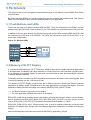
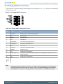
The kit has two user push buttons marked PB0 and PB1. They are connected to the EFM32, and are
debounced by RC filters with a time constant of 1ms. The buttons are connected to pins PC8 and PC9.
In addition to the two push buttons, the kit also features two yellow LEDs marked LED0 and LED1, that
are controlled by GPIO pins on the EFM32. The LEDs are connected to pins PC10 and PC11 in an
active-high configuration.
Figure 5.1. Buttons/LEDs
5.2 Memory LCD-TFT Display
A 1.28-inch SHARP Memory LCD-TFT has been added to the board to enable interactive applications
to be developed. The display has a high resolution of 128 by 128 pixels, and consumes very little power.
It is a reflective monochrome display, so each pixel can only be light or dark, and no backlight is needed
in normal daylight conditions.
The display interface consists of an SPI-compatible serial interface and some extra control signals. Data
is sent to the display one line (128 bits) at a time.
The Memory LCD-TFT display is shared with the kit Board Controller, allowing the Board Controller
application to display usefull information when the user application is not using the display. The user
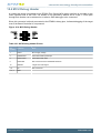
application always controls ownership of the display with EFM_DISP_SELECT (PA8):
• 0: The Board Controller has control of the display
• 1: The user application (EFM32) has control of the display
EFM_DISP_PWR (PA10) enables power to the display, and must be set high in order to use the display.
Data is clocked in on EFM_DISP_MOSI (PD7) when EFM_DISP_CS (PE11) is high, and the clock is
sent on EFM_DISP_SCLK (PC15). The maximum supported clock speed is 1.1 MHz.
EFM_DISP_COM (PE10) is the "COM Inversion" line. It must be pulsed periodically to prevent static
build-up in the display itself. Please refer to the display application information for details on driving the
display:
http://www.sharpmemorylcd.com/resources/LS013B7DH03_Application_Info.pdf
2013-10-08 - t0032_1.00
7
www.silabs.com