1
Operations Manual
Cooper Power Systems
ELECTRICAL APPARATUS
UM30 Three-Phase Frequency and Universal Voltage Relay
S150-22-1
CHANGING A SETTING ....................................................... 4
are programmable. All settings, measurements, and
programming of the relay are possible through its front
panel controls, or by means of a computer connected to
the relay’s RS485 communications port. The functions
provided by the UM30 are:
n Two frequency elements each configurable as either
under (81U), over (81O), or under and over (81U and
81O) elements.
n Two overexcitation elements (24).
n Two voltage elements each configurable as either
under (27), over (59), or under and over (27 and 59)
elements.
n One positive sequence voltage element configurable
as either an under (27pos), over (59pos), or under
and over (27pos and 59pos).
n One negative sequence overvoltage element
(59neg).
n Two zero sequence overvoltage elements (59zero),
with indication of the faulted phase.
The UM30 offers two programmable inputs, which can
serve to block the operation of the over and under
protective elements.
Separate pickup functions are also provided for all
elements which may be used to operate output relays to
in order to implement various control, blocking, logic, or
SCADA functions.
DESCRIPTION OF RELAY SETTING VARIABLES .................... 4
HANDLING
The Operations Manual is designed to familiarize the
reader with how to install, program, and set up the relay
for operation. For more detailed information regarding
the relay’s theory of operation, application notes, internal
schematics, service information, etc., please refer to the
UM30 section of the Edison® Relay Technical Reference
Manual, bulletin R150-00-1. Contact your local Cooper
Power Systems representative for ordering information.
CONTENTS
HANDLING ......................................................................... 1
INSTALLATION.................................................................... 2
ELECTRICAL CONNECTIONS ............................................... 2
OUTPUT RELAYS ............................................................... 2
BLOCKING INPUTS ............................................................. 2
TARGET DESCRIPTION ....................................................... 4
KEYBOARD OPERATION ..................................................... 4
PROGRAMMING THE RELAY ............................................... 4
CHANGING OUTPUT RELAY ASSIGNMENTS .......................... 7
BLOCKING VARIABLES ....................................................... 8
RUNNING THE TEST PROGRAMS......................................... 8
REAL TIME MEASUREMENTS .............................................. 8
LAST EVENT DATA ............................................................. 9
CUMULATIVE TRIP COUNTERS .......................................... 10
SPECIFICATIONS .............................................................. 11
SETTINGS SHEET FOR UM30 RELAY ................................ 12
INTRODUCTION
The UM30 relay provides all of the voltage and
frequency-related functions necessary for the protection
of a feeder or rotating equipment. Two digital inputs are
available to provide selective blocking of various
functions. Five output relays are provided, of which four
July 1998 1998 Cooper Industries, Inc. •New issue.
As with any piece of electronic equipment, care should be
taken when handling the relay, particularly in regards to
electrostatic discharge as the damage may not be
immediately obvious. All Edison relays are immune to
electrostatic discharge when left in their protective case.
However, when the relay is removed from its case, the
following practices should be observed.
n Touch the case to ensure that your body and the
relay are at the same potential.
n Whenever possible, handle the exposed relay by the
front panel, the rear connector, or by the edges of the
printed circuit boards. Avoid touching the individual
electronic components or the embedded traces on
the circuit boards.
n If you must hand the exposed (i.e., drawn-out) relay
to another person, make sure you are both at the
same electrical potential.
n When setting the drawn-out relay down, make sure
the surface is either anti-static in nature or is at the
same electrical potential as your body.
n Relays should always be placed in storage in their
protective cases. If storage of the drawn-out relay
outside of its protective case is required, then the
1
UM30 Relay operations manual
exposed relay should be placed in a suitable anti
static plastic or foam container.
INSTALLATION
Edison ‘M’ Series relays are shipped either in single or
double width cases, or in standard 19” 3RU rack mount
enclosures capable of housing up to four ‘M’ Series
relays. The double case mounting is similar to the single
case, but requires a 235 x 142mm panel opening. The
19” rack mount case is a standard 3RU high 19” cabinet.
See catalog section 150-00 for cabinet dimensions.
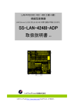
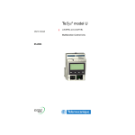
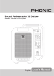
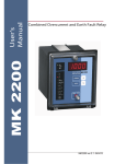
To remove the relay from its case, refer to Figure 1. The
relay may be removed from its protective case by turning
with a flat bladed screwdriver the locking screws À and Á
on the front panel latches  so that the slot on the screw
is parallel to the ground. The latches may then be pulled
from the inside edge to release the relay. Carefully pull on
the latches to remove the relay from the housing.
To re-install the relay in its case, align the printed circuit
boards with the guides in the relay case and slide the
relay in most of the way. For single and double cases,
make sure the locking arm on the back of each of the
latches  lines up with the locking pins in the case. Then
push the latches in, seating the relay. Turn the screws on
the latches until the slot is perpendicular to the ground.
Locked
Unlocked
Pull ->
Locked
Unlocked
FIGURE 1: LATCH MECHANISM FOR REMOVAL OF RELAY
FROM CASE
ELECTRICAL CONNECTIONS
Power is supplied via terminals 12 and 13, with common
at terminal 44. Chassis ground is made via the external
screw provided on the case. All Series ‘M’ relays are
available with one of two autoranging power supplies.
Descriptions of the input voltage ranges are given in
Table 1. The input supply voltage is noted on the relay
case. In the event the relay is fitted with the incorrect
power supply, the power supply boards are easily field
replaceable. See Bulletin S150-99-1 for instructions and
part numbers.
2
TABLE 1: POWER SUPPLY INPUT RANGES
Power
Supply
DC Voltage
Range
AC Voltage Range
L
24V (-20%) to
125V (+20%)
24V (-20%) to 110V
(+15%) 50/60 Hz
H
90V (-20%) to
250V (+20%)
80V (-20%) to 220V
(+15%) 50/60 Hz
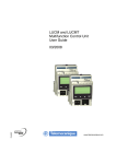
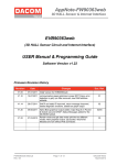
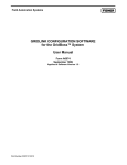
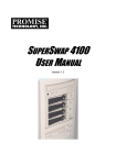
All electrical connections, including the RS485
connections, are made on the back of the relay. See
Figure 2. All the terminals will accept up to a No. 6 stud
size spade connector (or any type of lug up to 0.25”
wide), 12 AWG wire (4 mm²), or FASTON connectors.
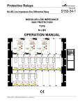
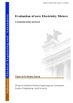
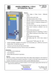
Electrical connections must be made in accordance with
the relay’s wiring diagram found in Figure 3. The
numbers next to the circles along the edge of the
functional block diagram of the relay indicate the terminal
numbers corresponding to the terminal numbers on the
back of the relay as shown in Figure 2. The VT inputs
must provide the relay with phase-to-ground voltages per
the phase rotation shown.
OUTPUT RELAYS
Output relays 1 through 4 are user programmable to
operate in conjunction with the tripping of any protective
element or elements. Relay 1 (R1) consists of two
isolated SPST (one From A and one Form B) terminals
as being either normally open or normally closed. The
other three output relays, R2, R3, and R4, all have Form
C (i.e., SPDT) contact arrangements.
Output relay 5 is normally energized (shown deenergized) and operates only upon power supply failure
or on an internal relay fault.
BLOCKING INPUTS
The UM30 has two inputs, which perform blocking
functions. The open circuit voltage across the terminals
of these inputs is 15 VDC. The internal resistance is 2.2 k
Ω. When the external resistance across these terminals
is less than 2.0kΩ, they are considered to be shorted.
See Programming the Relay for more information on the
function of these inputs.
S150-22-1
FIGURE 2: VIEW OF REAR TERMINAL CONNECTIONS
(21)
25
A
21
10
R1
DISPLAY
N.O.
11
22
26
MICROP.
B
FUNCTION
39
F27/59
29
R3
R2
41
F59s
30
F59Uo
F59/81
BT 2
R4
PROGR.
R5
44
UB
50
N.O.
19
N.C.
R4
R5
15
17
5
Uo
UA
18
20
4
6
R3
F81
EA
EC
(10)
R1
F27d/59d
UC
N.C.
8
28
C
7
9
R2
UM30-A
27
INT.FAULT
16
14
14
3
BI<
2
BI>
EB
1
12
_
KEYBOARD
=
C
S-
34/38
23
24
S+
13
1
9 PIN MALE
IEC 255
24(-20%)-110(+20%)Vac 24(-20%)-125(+20%)Vdc
80(-20%)-220(+20%)Vac 90(-20%)-250(+20%)Vdc
FIGURE 3 - UM30 WIRING DIAGRAM
3
UM30 Relay operations manual
TARGET DESCRIPTION
CHANGING A SETTING
The front panel of the UM30 contains eight LEDs, which
act as the targets for the relay elements. The top row of
four targets correspond to frequency, voltage, positive
sequence voltage, and negative sequence voltage
respectively. As soon as the measured quantities exceed
the trip level defined by the respective programming
variable, the appropriate LED begins to flash. Once the
time delay associated with that element has expired, the
relay will have tripped and the LED goes to a constant
ON state.
The two center RED LEDs on the bottom row correspond
to the volts/Hz and the zero sequence voltage elements.
The left most yellow LED will blink when the relay is in
programming mode and will illuminate constantly when
an internal relay failure has occurred. The right most
yellow LED will flash when either of the two blocking
inputs is active.
In case of an auxiliary power supply failure the status of
the targets is recorded to non-volatile memory. The
status of the targets is maintained when auxiliary power
is restored.
Once in active PROGRAM SETTINGS mode, you may
now change the relay settings. For instructions on
changing the output relay assignments see the section
titled Changing Output Relay Assignments. Change the
settings as follows:
1. Press the SELECT button to scroll through the
various input parameters available for
programming.
2. When the desired parameter to be changed is
displayed, press the + and – buttons to change
the displayed value. For numerical values where
the range of settings is large, the display may be
sped up by pressing the SELECT button at the
same time the + or – is pressed.
3. When the desired value in displayed, press the
ENTER/RESET button to store the new setting for
that parameter.
4. Repeat steps 1-3 for each setting.
5. When finished, press the MODE button to leave
programming mode and return the relay to normal
operation.
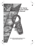
KEYBOARD OPERATION
All measurements, programmed settings, and recorded
data may be accessed through the front panel. The five
buttons are color-coded and their sequence of operation
is indicated on the front panel by means of arrows
directing the user to the next appropriate button to press.
Figures 4 and 5 give an overview of the keyboard
operation.
DESCRIPTION OF RELAY SETTING VARIABLES
This section describes each variable in the PROGRAM
SETTINGS mode. The following conventions are used:
•
PROGRAMMING THE RELAY
The relay may be programmed from the front panel or by
external computer control. This section will describe the
procedure for setting the relay from the front panel.
Consult the program’s User’s Manual for instructions on
programming the relay via software.
Two programming modes are available. The first is the
SETTINGS mode, where all of the input parameters (e.g.,
VT ratio, rated frequency) and settings (e.g., time delays,
etc.) are set. The second is the Fè
èRelay mode where
the various output relays are assigned to the various
protective elements. To enter program mode, follow
these steps:
1. Press the MODE button, to get into PROGRAM
mode.
2. Press the SELECT button to obtain either the
SETTINGS or Fè
èRelay display.
3. Using a thin tool (e.g., a small screwdriver) press
the recessed PROG button. The PROGRAM LED
will now be flashing, indicating that the
PROGRAM mode has been successfully entered.
4
The name of the variable and any unit of
measure displayed (Volts, Hz, etc.) is in bold
face type. Some variables do not have a unit
of measures displayed. An example of these
are variables that define curve shapes.
•
The default value is shown in regular
typeface.
For example:
Fn 50Hz
Fn is the name of
the variable.
Hz is the unit of
measure, Hertz.
50 is the setting
default.
A value of “Dis” in the Setting range column indicates that
when the variable is set to this value, the related function
is disabled.
S150-22-1
{
COOPER
Cooper Power Systems
STEP 1
Pressing this button progressively between
between Mesasurements Display, Settings
Display, Programming, and Test modes.
DISPLAY
MODE
+
SELECT
STEP 3
The + and - buttons are used to
select the actual measurement
or display desired when in
Measurements Display or Settings
Display modes. When in Program
mode, these buttons increase or
decrease the value ofthe displayed
setting.
STEP 2
The SELECT button chooses which category
of values within the chosen mode to display.
PROG
ENTER/RESET
STEP 5
When in Program mode, this button stores the newly
selected value. If not in Program mode and the relay
has tripped, this button resets the relay and all output
contacts. If not tripped, this button restores the default display.
STEP 4
When in Program mode, pressing this recessed button
places the relay into active programming mode,
allowing any or all of the relays settings to altered.
FIGURE 4 - KEYBOARD OPERATION
MODE
ACT MEAS
Measurements
Display Mode
SET DISP
Setting Display
Mode
PROGR
Programming
Mode
TEST PRG
Diagnositic Test
Mode
SELECT
+
ACT MEAS
Display actual measured values.
MAX. VAL.
Display maximum recorded values.
measured values
LastTr-x
Display data of last five events.
TRIP NUM
Display number of trips caused by
each protective function.
SETTINGS
Display programmed settings.
F-->RELAY
Display output contact assignments.
SETTINGS
Change
programmed
settings.
F-->RELAY
PROG
Active program
mode must be
enabled.
Change ouput
contact
assignments.
LEDSONLY
Run self test and operate LEDs only.
LED+TRIP
Run self test and operate LEDs and
output contacts.
–
ENTER
Scan the menus using the
+ and – keys.
1.Choose the setting to
change with the
SELECT button.
2.Change the value with
the + and – keys.
3.Store the new value
with the ENTER key.
Run the selected test by
pressing the ENTER
button.
FIGURE 5- KEY BOARD OPERATION OVERVIEW
5
UM30 Relay operations manual
TABLE 2: PROGRAM SETTING VARIABLES
DISPLAY
6
DESCRIPTION
SETTING RANGE
Fn 50Hz
System frequency
50 or 60 Hz
UnP 10kV
Rated primary phase to phase voltage of the system VTs
0.10 to 655 kV. Step size varies:
0.10 to 1.00 kV in 0.01 kV steps
1.1 to 9.9 kV in 0.1 kV steps
10 to 655kV in 1kV steps
UnS 100V
Rated secondary voltage of the system VTs
100 to 125 V in 1V steps
1φ
φ> 1.2pU
Trip level of the first V/Hz element
1.0 to 2.0 in 0.1 pu steps
K
Trip time delay coefficient of the first V/Hz element
0.5 to 5.0 in 0.1 steps
2φ
φ> 1.2pU
Trip level of the second V/Hz element
1.0 to 2.0 in 0.1 pu steps
t2φ
φ 5.0s
Trip time delay of the second V/Hz element
0.1 to 60 in 0.1 second steps
Fn -/+ f’
Operation mode of the first frequency control element
+ over-frequency, - under-frequency, -/+
under/over frequency, disable
f’ 0.50 Hz
Trip differential level of the first frequency control
element
0.05 to 9.9 in 0.01 Hz steps
tf’ 1.0 s
Trip time delay of the first frequency control element
0.1 to 60.0 in 0.1 steps
Fn - f”
Operation mode of the second frequency control element
+ over-frequency, - under-frequency, -/+
under/over frequency, disable
f”1.00 Hz
Trip differential level of the second frequency control
element
0.05 to 9.99 in 0.01 Hz steps
tf” 2.0 s
Trip time delay of second frequency control element
0.1 to 60 in 0.1 second steps
Un -/+ u’
Operation mode of the first voltage control element
+ overvoltage, - undervoltage, -/+
under/over voltage, disable
u’ 10%Un
Trip differential level of the first voltage control element
5 to 90 in 1% Un steps
tu’ 1.0 s
Trip time delay of the first voltage control element
0.1 to 60 in 0.1 second steps
Un -/+ u”
Operation mode of the second voltage control element
+ overvoltage, - undervoltage, -/+
under/over voltage, disable
u”20%Un
Trip differential level of the second voltage control
element
5 to 90 in 1% Un steps
tu” 2.0 s
Trip time delay of the second voltage control element
0.1 to 60 in 0.1 second steps
Edn-/+Ed
Operation mode of the positive sequence voltage
element
+ overvoltage, - undervoltage, -/+
under/over voltage, disable
Ed20%En
Trip differential level of the positive sequence voltage
element
5 to 90 in 1% En steps or disable
tEd 5.0s
Trip time delay of the positive sequence voltage element
0.1 to 60 in 0.1 second steps
Es10%En
Trip level of the negative sequence voltage element
1 to 99 in 1% En steps or disable
tEs 5.0 s
Trip time delay of the negative sequence voltage
element
0.1 to 60 in 0.1 second steps
U0> 10V”
Trip level of the low-set zero sequence voltage element
1 to 99 in 1.0 volt steps
t0> 0.5s
Trip time delay of the low-set zero sequence voltage
element
0.05 to 9.9 in 0.05 second steps
10.0 to 60.0 in 0.1 second steps
U0>>20V”
Trip level of the high-set zero sequence voltage element
1 to 99 in 1.0 volt steps
t0>> 0.2s
Trip time delay of the high-set zero sequence voltage
element
0.05 to 9.9 in 0.05 second steps
NodAd 1
Modbus communication address
1 to 250 in steps of 1
5.0
S150-22-1
CHANGING OUTPUT RELAY ASSIGNMENTS
Output relays R1 through R4 may be assigned to any
protective element, or any combination of elements. The
only exception is that the relay cannot be assigned to
both pick-up (start-time) elements, and time dependent
(delayed) protective elements.
1. First, enter the Fè
èRelay program mode.
2. Press the SELECT button to display the protective
element for which the relay assignments are to be
made or changed.
3. Press the + key to select the output relay. Each
press of the + key selects the next output relay.
Once selected, the relay position blinks.
4. Press the - key to toggle whether the element is
assigned to the output relay or not. If assigned,
the output relay number appears. If not, only a
hyphen (-) will be displayed.
5. Press the ENTER/RESET button to store the
changes.
6. Repeat steps 1 through 5 for each protective
element whose assignments you desire to
change.
7. For example:
This is the
tI> -2-4
TABLE 3 - OUTPUT RELAY PROGRAMMING DISPLAY
DEFINITIONS
DISPLAY
DESCRIPTION
f’
---4
Pick-up (or start-time) element associated
with the first frequency element
tf’
1---
Time delayed element associated with the
first frequency element
f”
---4
Pick-up element associated with the
second frequency element
tf”
-2--
Time delayed element associated with the
second frequency
u’
---4
Pick-up element associated with the first
voltage element
tu’
1---
Time delayed element associated with the
first voltage element
u”
---4
Pick-up element associated with the
second voltage element
tu”
-2--
Time delayed element associated with the
second voltage element
U0> ---4
Pick-up element associated with the lowset zero sequence voltage element
t0>
1---
Time delayed element associated with the
low-set zero sequence voltage element
U0>> ---4
Pick-up element associated with the highset zero sequence voltage element
t0>> --3-
Time delayed element associated with the
high-set zero sequence voltage element
Ed
---4
Pick-up element associated with the
positive sequence voltage element
tEd
--3-
Time delayed element associated with the
positive sequence voltage element
Es
---4
Pick-up element associated with the
negative sequence voltage element
tEs
--3-
Time delayed element associated with the
negative sequence voltage element
1φ
φ
---4
Pick-up element associated with the first
V/Hz element
DESCRIPTION OF OUTPUT RELAY VARIABLES
t1φ
φ
--3-
This section describes each variable in the PROGRAM,
Fè
èRelay mode. The following conventions are used:
Time delayed element associated with the
first V/Hz element
2φ
φ
---4
Pick-up element associated with the
second V/Hz element
t2φ
φ
--3-
Time delayed element associated with the
second V/Hz element
name of
protective
element. This dash means
that output relay
number 1 is not
assigned to this
element.
The number 2
means that output
relay 2 will operate
when this element
trips.
The number 4
means that output
relay 4 will operate
when this element
trips.
This dash means
that output relay
number 3 is not
assigned to this
element.
•
The name of the variable is in bold face type.
•
The default output relay settings are shown
in regular typeface.
7
UM30 Relay operations manual
TABLE 3 - OUTPUT RELAY PROGRAMMING DISPLAY
DEFINITIONS -- CONTINUED
DISPLAY
DESCRIPTION
R1tr3.0s
Reset mode for all elements associated
with output relay 1. Reset may be
programmed to take in one of three
manners:
1. Instantaneously upon the input or
calculated quantities dropping below
the pickup value. This is signified by
Aut in the display.
2. Automatically, but with a time delay
adjustable between 0.1 and 9.9
seconds in 0.1 second steps. (Default
is this mode with a 3 sec delay).
3. Manual reset (by front panel or
computer command) only. This is
signified by Man in the display.
R2tr Aut
Same as for R1tr but for output relay 2
assigned functions.
R3tr Aut
Same as for R1tr but for output relay 3
assigned functions.
R4tr Aut
Same as for R1tr but for output relay 4
assigned functions.
BLOCKING
VARIABLES
Two blocking inputs are provided. One input is dedicated
toward blocking all “under level” functions, and one
dedicated to blocking all “over level” functions as follows:
Blocking input BI>:
shorting terminals 1 and 2
activates This blocking input. The operation of any output
relay controlled by an “over level” function is inhibited for
as long as the input terminal pair is shorted. This includes
any over-frequency, over-voltage, positive sequence
over-voltage, negative sequence over-voltage, zero
sequence over-voltage, and over-volts/Hz elements.
Blocking input BI<:
shorting terminals 1 and 3
activates This blocking input. The operation of any output
relay controlled by an “under level” function is inhibited for
as long as the input terminal pair is shorted. This includes
any under-frequency, under-voltage, and positive
sequence under-voltage.
While the blocking inputs are active (i.e., shorted), the
tripping of any element associated with the blocking
input(s) is prevented. Continued sensing of the input
quantities and the countdown of any timers continues
however, so that when the blocking is removed, any
picked up elements will either trip instantaneously, or will
trip after any remaining time delay.
PROGRAMMING VIA SOFTWARE
The UM30 may also be programmed using any of the
programming interface software packages provided by
8
Cooper Power Systems or others. Please consult the
user manual for the appropriate software.
The UM30 uses the Modbus communication protocol.
For details on the memory map used in the UM30 in
order to interface it with other Modbus programs or
devices, consult the Edison ‘M’ Series Relay Technical
Reference Manual.
RUNNING THE TEST PROGRAMS
If desired, the start up diagnostic routines may be run at
any time by accessing the TEST PRG mode. Two tests
may be run, both of which are identical except for the
effect on the output relays.
1. Press the Mode button until TEST PRG is displayed.
2. Select the test to run by pressing the SELECT button
once to show LEDSONLY, or twice to display
LED+TRIP.
A. If the LEDSONLY test is selected, pressing the
ENTER/RESET button will run the test. All the
LEDs should illuminate during the duration of the
test. If an error is found, the error code will be
displayed and the RELAY FAIL light will remain
illuminated. The test lasts approximately five
seconds. No output relays will operate or change
status.
B. If the LED+TRIP test is selected, pressing the
ENTER/RESET button will then display
TestRun? To run the test the ENTER/RESET
button must be pressed again. At this point the
test will run and all of the output relays will also
be operated. The test lasts approximately five
seconds.
! CAUTION
Running the LED+TRIP test will operate all of the
output relays. Care must be taken to ensure that no
unexpected or harmful equipment operations will occur
as a result of running this test. It is generally
recommended that this test be run only when all
dangerous output connections are removed.
An external computer running the appropriate software
may also initiate these test routines.
REAL TIME MEASUREMENTS
To display the real-time measured values of the relay’s
quantities, enter the ACT MEAS mode of operation as
follows:
1. Press the MODE button, to get into MEASURES
mode.
2. Press the SELECT button to select the ACT
MEAS mode.
S150-22-1
3. Press the + or – buttons to scroll through the
available measurements. The data available is
summarized in Table 4.
TABLE 4 - AVAILABLE METERED VALUES IN “ACT MEAS”
MODE
DISPLAY
F
TABLE 5 - AVAILABLE LAST EVENT DATA IN “LASTTRIP”
MODE
DISPLAY
HISTORICAL QUANTITY
Cau:xxxx
“xxxx” is the element which caused
the last trip operation as follows:
MEASURED QUANTITY
f’
1st frequency element
f”
2nd frequency element
u’
1st voltage element
u”
2nd voltage element
O>A or O>B or O>C
Low set zero sequence
voltage element phase A, B,
or C
O>>A or O>>B or O>>C
High set zero sequence
voltage element phase A, B,
or C
Ed
Positive sequence voltage
element
Es
Negative sequence voltage
element
1φ
1st V/Hz element
2φ
2nd V/Hz element
System frequency
Ua
Phase A - B voltage
Ub
Phase B - C voltage
Uc
Phase C - A voltage
U0
Zero sequence voltage
Ea
Phase A - neutral voltage
Eb
Phase B - neutral voltage
Ec
Phase C - neutral voltage
Ed
Positive sequence voltage
Es
Negative sequence voltage
LAST EVENT DATA
The relay stores all information associated with the last
trip event. To access this data, enter the LASTTRIP
mode of operation as follows:
1. Press the MODE button, to get into MEASURES
mode.
2. Press the SELECT button to select the LASTTRIP
mode.
3. Press the + or – buttons to scroll through the
event record. The data available is summarized
in Table 5.
F
Frequency at time of trip
Ua
Phase A - B voltage at time of trip
Ub
Phase B - C voltage at time of trip
Uc
Phase C - A voltage at time of trip
U0
Zero sequence Voltage at time of trip
Ed
Positive sequence Voltage at time of
trip
Es
Negative sequence Voltage at time of
trip
9
UM30 Relay operations manual
CUMULATIVE TRIP COUNTERS
To display how many times the relay has tripped for each
of the protective elements, enter the TRIP NUM mode of
operation as follows:
1. Press the MODE button, to get into MEASURES
mode.
2. Press the SELECT button to select the TRIP NUM
mode.
3. Press the + or – buttons to scroll through the
available measurements. The data available is
summarized in Table 6.
TABLE 6 - CUMULATIVE TRIP COUNTER DATA IN “TRIP
NUM” MODE
10
DISPLAY
NUMBER OF TRIPS DUE TO...
f’ xxxxx
1st frequency delayed element
f” xxxxx
2nd frequency delayed element
u’ xxxxx
1st voltage delayed element
u” xxxxx
2nd voltage delayed element
U0> xxxx
Low set zero sequence voltage
delayed element
U0>>xxxx
High set zero sequence voltage
delayed element
Ed xxxxx
Positive sequence voltage delayed
element
Es xxxxx
Negative sequence voltage delayed
element
1φ> xxxx
1st V/Hz delayed element
2φ> xxxx
2nd V/Hz delayed element
S150-22-1
SPECIFICATIONS
Operating Temperature Range ........................................................................................................................................-20 to +60°C at 95% humidity
Storage Temperature.................................................................................................................................................................................-30 to +80°C
Rated Input Voltage .............................................................................................................................................................................................. 125V
Voltage Circuits Overload ................................................................................................................................................................. 2.0 pu Continuous
Burden on Voltage Inputs...........................................................................................................................................................0.2 VA at rated voltage
Dielectric test Voltage ........................................................................................................................................................... 2000V, 50/60Hz, 1 minute
Impulse Test Voltage ..................................................................................................5kV common mode, 1 kV differential mode, 1.2 x 50 µsec wave
Immunity to high frequency burst ......................................................................................... 1 kV common mode, 0.5 kV differential mode at 100 kHz,
.......................................................................................................................... 2.5 kV common mode, 1 kV differential mode at 1 MHz
Immunity to electrostatic discharge.......................................................................................................................................................................15 kV
Immunity to Sinusoidal Wave Burst ...............................................................................................................................100V over 10 - 1000kHz range
Immunity to radiated electromagnetic field..................................................................................................................10V/m over 20 - 1000MHz range
Immunity to High Energy Burst .....................................................................................................................4 kV common mode, 2V differential mode
Immunity to 50/60Hz magnetic field ................................................................................................................................................................1000 A/m
Immunity to impulse magnetic field ................................................................................................................................................. 1000 A/m 8 x 20 µs
Immunity to magnetic burst..................................................................................................................................... 100 A/m over 100 - 1000kHz range
Resistance to vibration.....................................................................................................................................................................1g from 10 -500 Hz
Rear Connection Terminals ................................................................................................................................. Up to 12AWG (4mm²) stranded wire
...................................................................................................................Lugs up to 0.25 inch (6.5mm) wide, or FASTON connectors
Output Contacts ................................................................................................................................................................................. rated current 5 A
................................................................................................................................................................................. rated voltage 380 V
....................................................................................................... nominal switching power with AC resistive load 1100W(380V max.)
........................................................................................... breaking capacity at 110 VDC: 0.3A with L/R=40ms for 100,000 operations
..................................................................................................................................make and carry capacity for 0.5 sec = 30 A (peak)
................................................................................................................................mechanical life over 2,000,000 (2 x 10⁶) operations
PC Board Connectors ...................................................................................................................................Gold plated, 10A continuous, 200A 1 sec.
Power Supply Input Voltage Range: ............................................................................................................Two Available at 24 - 110 V AC-DC ± 20%
.................................................................................................................................................................. or 90 - 220 V AC-DC; ± 20%
AError! Objects cannot be created from editing field codes.erage Power Supply consumption8Error! Objects cannot be created from editing field code
Weight (in single relay case) ................................................................................................................................................................... 2.3kg (5.0lbs)
11
UM30 Relay operations manual
SETTINGS SHEET FOR UM30 RELAY - PAGE 1 OF 4
Variable
Factory
default
Fn
50
Hz
System frequency
50 or 60 Hz
--
UnP
10KV
Primary
volts or
kV
Rated primary phase-to-phase
voltage of the system VTs
0.10 to 655 kV
0.01 kV (0.1-1)
0.1 kV (1.1-9.9)
1.0 kV (10-655)
UnS
100
Volts
Rated secondary phase-to-phase
voltage of the system VTs
100 to 125 V
1V
1φ
1.2
Per unit
Trip level of the first V/Hz element
1.0-2.0 per unit,
disable
0.1
K
5.0
----
Trip time delay coefficient of the
first V/Hz element
0.5-5.0
0.1
2φ
1.2
Per unit
Trip level of the second V/Hz
element
1.0-2.0 per unit,
disable
0.1
t2φ
5.0
seconds
Trip time delay of the second V/Hz
element
0.1-60.0 seconds
0.1
Fn –/+ f’
–/+
----
Operation mode of the first
frequency control element
–, +, –/+, disable
--
F’
0.5
Hz
Trip differential level of the first
frequency control element
0.05-9.99 Hz
0.01
tf’
1.0
seconds
Trip time delay of the first frequency
control element
0.1-60.0 seconds
0.1
Fn –f”
–
----
Operation mode of the second
frequency control element
–, +, –/+, disable
--
F”
1.00
Hz
Trip differential level of the second
frequency control element
0.05-9.99 Hz
0.01
tf”
2.0
seconds
Trip time delay of second frequency
control element
0.1-60.0 seconds
0.1
Un –/+ u’
–/+
----
Operation mode of the first voltage
control element
–, +, –/+, disable
--
U’
10
% rated
voltage
Trip differential level of the first
voltage control element
5-90% Un
1
tu’
1.0
seconds
Trip time delay of the first voltage
control element
0.1-60.0 seconds
0.1
Un + u”
+
----
Operation mode of the second
voltage control element
–, +, –/+, disable
--
U”
20
% rated
voltage
Trip differential level of the second
voltage control element
5-90% Un
1
tu”
2.0
seconds
Trip time delay of the second
voltage control element
0.1-60.0 seconds
0.1
Edn
–/+
----
Operation mode of the positive
sequence voltage element
–, +, –/+, disable
--
Ed
20
% rated
voltage
Trip differential level of the positive
sequence voltage element
5-90% En
1
tEd
5.0
seconds
Trip time delay of the positive
sequence voltage element
0.1-60.0 seconds
0.1
12
Units
Description
Range
Step
Setting
S150-22-1
SETTINGS SHEET FOR UM30 RELAY - PAGE 2 OF 4
Variable
Factory
default
Es
10
tEs
Units
Description
Range
Step
% rated
voltage
Trip level of the negative sequence
voltage element
1-99% En, disable
1
5.0
seconds
Trip time delay of the negative
sequence voltage element
0.1-60.0 seconds
0.1
U0>
10
Volts
Trip level of the low-set zero
sequence voltage element
1-99 volts, disable
1V
t0 >
0.5
seconds
Trip time delay of the low-set zero
sequence voltage element
0.05-60.0 seconds
0.05 (0.05-9.9)
0.1 (10.0-60.0)
U0>>
20
Volts
Trip level of the high-set zero
sequence voltage element
1-99 volts, disable
1V
t0>>
0.2
seconds
Trip time delay of the high-set zero
sequence voltage element
0.05-9.9 seconds
0.05
NodAd
1
None
Modbus communication address
1-250
1
Setting
13
UM30 Relay operations manual
SETTINGS SHEET FOR UM30 RELAY - PAGE 3 OF 4
OUTPUT RELAY PROGRAMMING ASSIGNMENTS (ACCESSIBLE VIA THE Fè
èRelay PROGRAM MODE.)
Variable
Factory
default
Units
Description
Range
f’
---4
Outputs
Pick-up (or start-time) element associated with the first
frequency element
1234
tf’
1---
Outputs
Time delayed element associated with the first frequency
element
1234
f”
---4
Outputs
Pick-up element associated with the second frequency
element
1234
tf”
-2 --
Outputs
Time delayed element associated with the second
frequency
1234
u’
---4
Outputs
Pick-up element associated with the first voltage element
1234
tu’
1---
Outputs
Time delayed element associated with the first voltage
element
1234
u”
---4
Outputs
Pick-up element associated with the second voltage
element
1234
tu”
-2--
Outputs
Time delayed element associated with the second voltage
element
1234
U0>
---4
Outputs
Pick-up element associated with the low-set zero
sequence voltage element
1234
t0>
1---
Outputs
Time delayed element associated with the low-set zero
sequence voltage element
1234
U0>>
---4
Outputs
Pick-up element associated with the high-set zero
sequence voltage element
1234
t0>>
--3-
Outputs
Time delayed element associated with the high-set zero
sequence voltage element
1234
Ed
---4
Outputs
Pick-up element associated with the positive sequence
voltage element
1234
tEd
--3-
Outputs
Time delayed element associated with the positive
sequence voltage element
1234
ES
---4
Outputs
Pick-up element associated with the negative sequence
voltage element
1234
tEs
--3-
Outputs
Time delayed element associated with the negative
sequence voltage element
1234
1φ
---4
Outputs
Pick-up element associated with the first V/Hz element
1234
t1φ
--3-
Outputs
Time delayed element associated with the first V/Hz
element
1234
2φ
---4
Outputs
Pick-up element associated with the second V/Hz element
1234
14
Setting
S150-22-1
SETTINGS SHEET FOR UM30 RELAY - PAGE 4 OF 4
Variable
Factory
default
Units
Description
Range
t2φ
--3-
Outputs
Time delayed element associated with the second V/Hz
element
R1tr
3.0
seconds
Reset characteristic of output relay R1
seconds,
Manual, or
Auto
R2tr
Aut.
----
Reset characteristic of output relay R2
seconds,
Manual, or
Auto
R3tr
Man.
----
Reset characteristic of output relay R3
seconds,
Manual, or
Auto
R4tr
Aut.
----
Reset characteristic of output relay R4
seconds,
Manual, or
Auto
Setting
1234
15
UM30 Relay operations manual
Quality from
Cooper Industries
© 1998 Cooper Power Systems, Inc.
53187
Edison® is a registered trademark of Cooper Industries, Inc.
P.O. Box 1640, Waukesha, WI
http://www.cooperpower.com/
Cooper Power Systems
16