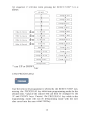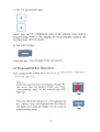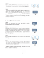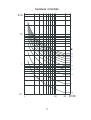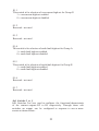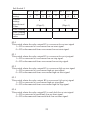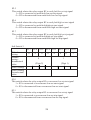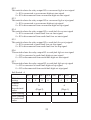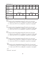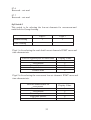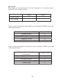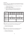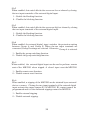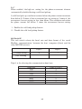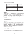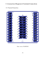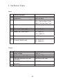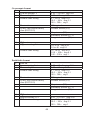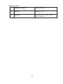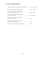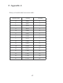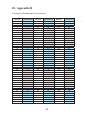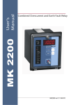
1
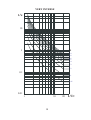
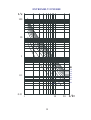
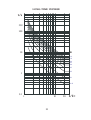
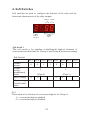
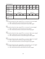
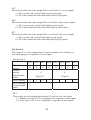
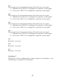
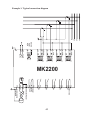
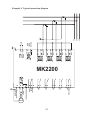
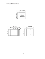
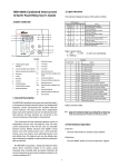
MK 2200 User's Manual Combined Overcurrent and Earth Fault Relay Features Multifunction numerical relay Phase overcurrent & earth fault protection Two sets of low-set & high-set setting Four IDMT curves Definite time setting Instantaneous trip time setting Phase & earth fault currents metering Nine tripping records Flexible programmable outputs Multifunction external digital input Isolated RS485 Modbus communication Table of Contents Page 1. Introduction 2 2. Description of Operation 3 3. Characteristic Curves 16 4. Soft Switches 21 5. Connection Diagram & Terminal Connection 38 6. Case Dimensions 42 7. Technical Data 43 8. Tests and Standards 46 9. Appendix A 47 10. Appendix B 48 For continuous product development, we reserve the right to supply equipment which may vary from that described in this manual. 1 1. Introduction The MK2200 combined overcurrent and earth-fault relay is a digital microprocessor based relay. This relay employs extensive advanced numerical techniques which are implemented in real time, for the computation of measured input quantity. Other advanced features include programmable control output, metering and fault data storage. A fully digital user interface with bright seven-segment display provides a very user-friendly access to all the relay settings, meters and fault data. MK2200 can be connected to a network system through its RS485 Modbus -RTU communication channel. 2 2. Description of Operation The MK2200 relay provides three independent phase overcurrent elements and one non-directional earth-fault element. All these elements are connected to the current transformers of the feeders to be protected. The current inputs can be configured for operation with either 1A or 5A current transformers by connecting the current transformers to the appropriate terminals of the MK2200 relay. 2.1 Phase Overcurrent Protection Phase overcurrent protection consists of low-set stage and high-set stage for each phase overcurrent element of IL1, IL2, & IL3. All the three phases share the same low-set & high-set settings. When the phase current exceeded the low-set stage I> setting, the lowset overcurrent element starts by delivering a start signal to the display panel and a group of user pre-assigned contact outputs. If the phase current continue to exceed the low-set stage I> setting for a period of time, the low-set element trips by delivering a trip signal to the display panel and a group of user pre-assigned contact outputs. This time delay is determined by the low-set time delay setting (t>) or the time-current characteristic of the selected inverse definite minimum time (IDMT) curve. Similarly, the high-set stage I>> of the overcurrent element starts once the set I>> current is exceeded. After a preset delay time of t>>, the overcurrent element operates and trips the relay by delivering a trip signal to the display panel and a group of user pre-assigned contact outputs. There are two groups of phase overcurrent settings, namely, Group A and Group B. Each group has one high-set and one low-set and both the high-set stage and low-set stage function independently. Group selection is done by the external digital input with the appropriate setting of soft switch 9. 2.2 Earth-Fault Protection Earth-fault protection element consists of independent low-set and highset stages. 3 When the earth fault current exceeded the low-set stage Io> setting, the low-set earth fault element starts by delivering a start signal to the display panel and a group of user pre-assigned contact outputs. If the earth fault current continue to exceed the low-set stage Io> setting for a period of time, the low-set element trips by delivering a trip signal to the display panel and a group of user pre-assigned contact outputs. This time delay is determined by the low-set time delay setting (to>) or the time-current characteristic of the selected inverse definite minimum time (IDMT) curve. Similarly, the high-set stage Io>> of the overcurrent element starts once the set Io>> current is exceeded. After a preset delay time of to>>, the overcurrent element operates and trips the relay by delivering a trip signal to the display panel and a group of user pre-assigned contact outputs. There are two groups of earth fault settings, namely, Group A and Group B. Each group has one high-set and both the high-set stage and low-set stage function independently. Group selection is done by the external external digital input with the appropriate setting of soft switch 9. 2.3 Measuring Elements All the three overcurrent elements and one earth-fault element are provided with user selectable 1A or 5A current transformer inputs. The MK2200 settings are normalized to 1A. If 5A current transformers are used, the user is required to connect the current transformers to the 5A block terminal inputs and normalize all required setting values to 1A before entering it into the relay. For each measuring elements, there is one independent high-set and one independent low-set. The elements' overcurrent or earth-fault low-set tripping time current characteristics are selectable between inverse definite minimum time (IDMT) normal inverse curve, long time inverse curve, very inverse curve, extremely inverse curve and definite time. The overcurrent elements and earthfault element tripping time current characteristic curves are individually selectable. The high-set tripping characteristic for both overcurrent element and earth fault element are of the definite time type. Instantaneous tripping is made possible by setting the time to minimum. 4 2.4 Digital Inputs The functions of this external binary input are o o o o Blocking the operation of one or more protection stages. Resetting a latched output relay in the manual reset mode. Selection of protection setting group - Group A or Group B. Trip input to operate contact R1. The input source can be either ac or dc. 2.5 Output Contacts MK2200 has six relay outputs of which 4 are user configurable. Contact R1 is the dedicated trip contact and cannot be programmed. Either earth fault or overcurrent will activate this contact. Contacts R2, R3, R4 and R5 are user configurable outputs. The sixth output contact IRF is also not user programmable. It is used to signal an internal failure of MK2200. 2.5.1 User programmable outputs Output contacts R2, R3, R4 and R5 can be programmed as follows: o Linked to overcurrent low-set starting o Linked to overcurrent low-set tripping o Linked to overcurrent high-set starting o Linked to overcurrent high-set tripping o Linked to earth fault low-set starting o Linked to earth fault low-set tripping o Linked to earth fault high-set starting o Linked to earth fault high-set tripping o Manual reset or auto reset for contact outputs R1,R2,R3,R4&R5 2.5.2 Internal Relay Failure (IRF) output When the auxiliary power of MK2200 is switched on, the relay starts operation. If the MK2200 is functioning normally, the IRF output is energized hence the NC contact of the output will open and the NO contact will close. 5 2.6 Display a) This indicator indicates the presence of auxiliary power supply to MK2200. b) When any of the 3 phases or the earth fault protection elements is started (pick-up), this indicator lights up. c) When any of the 3 phases or the earth fault protection elements is first started and then subsequently tripped, this indicator lights up to signal a tripped condition . 6 d) Number Value The 4-digit display is for displaying the value of the selected item and its corresponding number.The left-most digit represents the number or group selection and the right-most 3 digits represent the value. e) Phase L1 current is selected. When selected, the 4-digit display indicates the measured phase L1 current. f) Phase L2 current is selected. When selected, the 4-digit display indicates the measured phase L2 current. g) Phase L3 current is selected. When selected, the 4-digit display indicates the measured phase L3 current. h) Earth fault current is selected. When selected,the 4-digit display indicates the measured earth fault current. i) This indicator lights up simultaneously with either indicators I L1, IL2 I L3 or indicator I LO. When selected, the digit display shows the latest tripping fault current of the corresponding phases IL1, IL2, IL3 or ILO. 7 There are nine sets of trip records. To view other records, press the UP or DOWN key. Record 1 is the latest record. Note that the fault values recorded are at the moment of tripping. j) When selected, the 4-digit display shows the latest relay start time. This is the time from relay pick-up until the fault current is removed. The minimum time is 0.1 second. k) When selected, the 4-digit display shows the overcurrent low-set current setting. The left-most digit on the 4-digit display indicates either Group A or Group B selection.The setting value is expressed as ratio of Isetting/Irated. Examples: Group A Setting Value 80% Group B Setting Value 100% l) When selected, depending on the setting of soft switch 8 and 9, the digit display shows the overcurrent time multiplier setting or the low-set time delay setting. Refer to page 21 for the soft switch selection. The left-most digit on the 4-digit display indicates either Group A or Group B setting selection. When time delay is selected, the unit is second. 8 m) When selected, the 4-digit display shows the overcurrent high- set setting. The left-most digit on the 4-digit display indicates either Group A or Group B setting selection. n) When selected, the digit display shows the overcurrent high -set time delay setting. The left-most digit on the 4-digit display indicates either Group A or Group B setting selection. o) When selected, the digit display shows the earth fault low-set setting. The left-most digit on the 4-digit display indicates either Group A or Group B setting selection. p) When selected, depending on the setting of soft switch 8 and 9, the digit display shows the earth fault time multiplier setting or the low-set time delay setting. Refer to page 21 for the soft switch selection. The left-most digit on the 4-digit display indicates either Group A or Group B setting selection. 9 q) When selected, the 4-digit display shows the earth fault high-set setting. The left-most digit on the 4-digit display indicates either Group A or Group B setting selection. r) When selected, the 4-digit display shows the earth fault high- set time delay setting. The left-most digit on the 4-digit display indicates either Group A or Group B setting selection. s) This indicator reflect the status of the external digital input regardless of the soft-switch A selection. t) Normal Status Display Under normal operating condition,all the indicators are off except the following: i) The Aux indicator shows the presence of auxiliary power supply. ii) Blinking 10 The decimal point on the left- most digit blinks to indicate that the relay is functioning. u) Start Status Display i) START indicator lights up to indicate relay pick-up. ii) One or more of the following indicator(s) blinks to indicate the source(s) of the pick-up. v) Trip Status Display i) TRIP indicator lights up to indicate the relay is in a tripped condition. ii) One of the indicators below blink to indicate the source of tripping. 11 iii) One of the indicators below blink to indicate the tripping element. iv) The digit display indicates the value of the tripping current. The leftmost blinking digit indicates the record number Record Number Value 2.7 Key Button Input a) RESET / STEP key This key has two functions i ) To reset the relay when the relay is tripped. ii ) To select the displayed item on the digit display under normal condition. 12 3. Characteristic Curves Both the low - set overcurrent and earth - fault elements can be independently configured to have following IDMT characteristic curves: . Normal inverse . Very inverse . Extremely inverse . Long-time inverse The relationship between current and time for the above curves comply with the standard IEC255-3 and may generally be expressed as: t = Kβ ( Ι/ Ι>) α − 1 Where, t = operating time in seconds K = time multiplier I = measured current I> = set current α = constant β = constant Characteristic curve α β Normal Inverse 0.02 0.14 Very Inverse 1.00 13.50 Extremely Inverse 2.00 80.00 Long-time Inverse 1.00 120.00 The overcurrent low-set and earth fault low- set elements can also be independently configured for definite time delay instead of the above inverse time delay. The overcurrent high - set and earth fault high - set elements are independently configured with definite time delay only.The time delay can be from 0 sec (instantaneous) to 300 sec. The high -set feature can also be disabled by the user. 16 NORMAL INVERSE t/s 10 K 1.0 0.9 0.8 0.7 0.6 0.5 1 0.4 0.3 0.2 0.1 0.1 0.05 1 10 17 20 I/I> VERY INVERSE t/s 10 1 K 1.0 0.8 0.6 0.5 0.4 0.3 0.2 0.1 0.1 0.05 0.01 1 0 18 20 I/I> EXTREMELY INVERSE t/s 100 10 1 K 1.0 0.8 0.6 0.5 0.4 0.3 0.1 0.05 0.01 1 10 19 0.2 0.1 20 I/I> LONG-TIME INVERSE t/s 200 100 10 K 1.0 0.8 0.6 0.5 0.4 0.3 0.2 1 0.1 0.05 0.1 10 1 20 20 I/I> 4. Soft Switches Soft switches are used to configure the features of the relay and the functional characteristic of the relay outputs. Digit2 Digit1 Switch Value Switch Number Soft Switch 1 This soft switch is for enabling or disabling the high-set elements of overcurrent and earth fault for Group A and Group B protection settings. Soft Switch 1 Default setting Default setting hexadecimal Value User’s setting User’s setting -hexadecimal value S1.7 S1.6 S1.5 S1.4 S1.3 S1.2 S1.1 S1.0 0 0 1 1 0 0 1 1 3 3 (Digit 2) 0 (Digit 1) 0 0 0 S1.0 This switch is for selection of overcurrent high-set for Group A 1 = overcurrent high-set enabled. 0 = overcurrent high-set disabled. 21 S1.1 This switch is for selection of overcurrent high-set for Group B 1 = overcurrent high-set enabled. 0 = overcurrent high-set disabled. S1.2 Reserved - not used S1.3 Reserved - not used S1.4 This switch is for selection of earth fault high-set for Group A 1 = earth fault high-set enabled. 0 = earth fault high-set disabled. S1.5 This switch is for selection of earth fault high-set for Group B 1 = earth fault high-set enabled. 0 = earth fault high-set disabled. S1.6 Reserved - not used S1.7 Reserved - not used Soft Switches 2 to 5 Soft Switches 2 to 5 are used to configure the functional characteristic of the contact outputs R2 to R5 respectively. Through these soft switches, an output can be configured to response to one or more events as shown below: 22 Soft Switch 2 Default setting Default setting hexadecimal Value User’s setting User’s setting -hexadecimal value S2.7 S2.6 S2.5 S2.4 S2.3 S2.2 S2.1 S2.0 0 0 0 0 0 0 0 0 0 0 (Digit 2) (Digit 1) S2.0 This switch relates the relay output R2 to overcurrent low-set start signal 1 = R2 is connected to overcurrent low-set start signal. 0 = R2 is disconnected from overcurrent low-set start signal. S2.1 This switch relates the relay output R2 to overcurrent low-set trip signal 1 = R2 is connected to overcurrent low-set trip signal. 0 = R2 is disconnected from overcurrent low-set trip signal. S2.2 This switch relates the relay output R2 to overcurrent high-set start signal 1 = R2 is connected to overcurrent high-set start signal. 0 = R2 is disconnected from overcurrent high-set start signal. S2.3 This switch relates the relay output R2 to overcurrent high-set trip signal 1 = R2 is connected to overcurrent high-set trip signal. 0 = R2 is disconnected from overcurrent high-set trip signal. S2.4 This switch relates the relay output R2 to earth fault low-set start signal 1 = R2 is connected to earth fault low-set start signal. 0 = R2 is disconnected from earth fault low-set start signal. 23 S2.5 This switch relates the relay output R2 to earth fault low-set trip signal 1 = R2 is connected to earth fault low-set trip signal. 0 = R2 is disconnected from earth fault low-set trip signal. S2.6 This switch relates the relay output R2 to earth fault high-set start signal 1 = R2 is connected to earth fault high-set start signal. 0 = R2 is disconnected from earth fault high-set start signal. S2.7 This switch relates the relay output R2 to earth fault high-set trip signal 1 = R2 is connected to earth fault high-set trip signal. 0 = R2 is disconnected from earth fault high-set trip signal. Soft Switch 3 Default setting Default setting hexadecimal value User’s setting User’s setting -hexadecimal value S3.7 S3.6 S3.5 S3.4 S3.3 S3.2 0 0 0 0 0 0 S3.1 0 S3.0 1 1 0 (Digit 2) (Digit 1) S3.0 This switch relates the relay output R3 to overcurrent low-set start signal 1 = R3 is connected to overcurrent low-set start signal. 0 = R3 is disconnected from overcurrent low-set start signal. S3.1 This switch relates the relay output R3 to overcurrent low-set trip signal 1 = R3 is connected to overcurrent low-set trip signal. 0 = R3 is disconnected from overcurrent low-set trip signal. 24 S3.2 This switch relates the relay output R3 to overcurrent high-set start signal 1 = R3 is connected to overcurrent high-set start signal. 0 = R3 is disconnected from overcurrent high-set start signal. S3.3 This switch relates the relay output R3 to overcurrent high-set trip signal 1 = R3 is connected to overcurrent high-set trip signal. 0 = R3 is disconnected from overcurrent high-set trip signal. S3.4 This switch relates the relay output R3 to earth fault low-set start signal 1 = R3 is connected to earth fault low-set start signal. 0 = R3 is disconnected from earth fault low-set start signal. S3.5 This switch relates the relay output R3 to earth fault low-set trip signal 1 = R3 is connected to earth fault low-set trip signal. 0 = R3 is disconnected from earth fault low-set trip signal. S3.6 This switch relates the relay output R3 to earth fault high-set start signal 1 = R3 is connected to earth fault high-set start signal. 0 = R3 is disconnected from earth fault high-set start signal. S3.7 This switch relates the relay output R3 to earth fault high-set trip signal 1 = R3 is connected to earth fault high-set trip signal. 0 = R3 is disconnected from earth fault high-set trip signal. Soft Switch 4 Default setting Default setting hexadecimal value User’s setting User’s setting -hexadecimal value S4.7 S4.6 S4.5 S4.4 S4.3 S4.2 S4.1 S4.0 0 0 0 0 1 0 1 0 0 A (Digit 1) (Digit 2) 25 S4.0 This switch relates the relay output R4 to overcurrent low-set start signal 1 = R4 is connected to overcurrent low-set start signal. 0 = R4 is disconnected from overcurrent low-set start signal. S4.1 This switch relates the relay output R4 to overcurrent low-set trip signal 1 = R4 is connected to overcurrent low-set trip signal. 0 = R4 is disconnected from overcurrent low-set trip signal. S4.2 This switch relates the relay output R4 to overcurrent high-set start signal 1 = R4 is connected to overcurrent high-set start signal. 0 = R4 is disconnected from overcurrent high-set start signal. S4.3 This switch relates the relay output R4 to overcurrent high-set trip signal 1 = R4 is connected to overcurrent high-set trip signal. 0 = R4 is disconnected from overcurrent high-set trip signal. S4.4 This switch relates the relay output R4 to earth fault low-set start signal 1 = R4 is connected to earth fault low-set start signal. 0 = R4 is disconnected from earth fault low-set start signal. S4.5 This switch relates the relay output R4 to earth fault low-set trip signal 1 = R4 is connected to earth fault low-set trip signal. 0 = R4 is disconnected from earth fault low-set trip signal. S4.6 This switch relates the relay output R4 to earth fault high-set start signal 1 = R4 is connected to earth fault high-set start signal. 0 = R4 is disconnected from earth fault high-set start signal. S4.7 This switch relates the relay output R4 to earth fault high-set trip signal 1 = R4 is connected to earth fault high-set trip signal. 0 = R4 is disconnected from earth fault high-set trip signal. 26 Soft Switch 5 Default setting Default setting hexadecimal value User’s setting User’s setting -hexadecimal value S5.7 S5.6 S5.5 S5.4 S5.3 S5.2 S5.1 S5.0 1 0 1 0 0 0 0 0 A 0 (Digit 2) (Digit 1) S5.0 This switch relates the relay output R5 to overcurrent low-set start signal 1 = R5 is connected to overcurrent low-set start signal. 0 = R5 is disconnected from overcurrent low-set start signal. S5.1 This switch relates the relay output R5 to overcurrent low-set trip signal 1 = R5 is connected to overcurrent low-set trip signal. 0 = R5 is disconnected from overcurrent low-set trip signal. S5.2 This switch relates the relay output R5 to overcurrent high-set star t signal 1 = R5 is connected to overcurrent high-set start signal. 0 = R5 is disconnected from overcurrent high-set start signal. S5.3 This switch relates the relay output R5 to overcurrent high-set trip signal 1 = R5 is connected to overcurrent high-set trip signal. 0 = R5 is disconnected from overcurrent high-set trip signal. S5.4 This switch relates the relay output R5 to earth fault low-set start signal 1 = R5 is connected to earth fault low-set start signal. 0 = R5 is disconnected from earth fault low-set start signal. 27 S5.5 This switch relates the relay output R5 to earth fault low-set trip signal 1 = R5 is connected to earth fault low-set trip signal. 0 = R5 is disconnected from earth fault low-set trip signal. S5.6 This switch relates the relay output R5 to earth fault high-set star t signal 1 = R5 is connected to earth fault high-set start signal. 0 = R5 is disconnected from earth fault high-set start signal. S5.7 This switch relates the relay output R5 to earth fault high-set trip signal 1 = R5 is connected to earth fault high-set trip signal. 0 = R5 is disconnected from earth fault high-set trip signal. Soft Switch 6 Soft Switch 6 is for configuring the contact outputs to be latching or non-latching type in response to a start signal. Soft Switch 6 Default setting Default setting hexadecimal value User’s setting User’s setting -hexadecimal value S6.7 S6.6 S6.5 S6.4 S6.3 S6.2 S6.1 S6.0 0 0 0 0 0 0 0 0 0 0 (Digit 1) (Digit 2) 0 0 0 S6.0 This switch set the relationship between R1 and the relay start signal. 1 = Manual reset of R1 if it is configured to response to start signal. 0 = Auto reset of R1 if it is configured to response to start signal. 28 S6.1 This switch set the relationship between R2 and the relay start signal. 1 = Manual reset of R2 if it is configured to response to start signal. 0 = Auto reset of R2 if it is configured to response to start signal. S6.2 This switch set the relationship between R3 and the relay start signal. 1 = Manual reset of R3 if it is configured to response to start signal. 0 = Auto reset of R3 if it is configured to response to start signal. S6.3 This switch set the relationship between R4 and the relay start signal. 1 = Manual reset of R4 if it is configured to response to start signal. 0 = Auto reset of R4 if it is configured to response to start signal. S6.4 This switch set the relationship between R5 and the relay start signal. 1 = Manual reset of R5 if it is configured to response to start signal. 0 = Auto reset of R5 if it is configured to response to start signal. S6.5 Reserved – not used S6.6 Reserved – not used S6.7 Reserved – not used Soft Switch 7 Soft Switch 7 is for configuring the contact outputs to be latching or nonlatching type in response to a trip signal. 29 Soft Switch 7 Default setting Default setting hexadecimal value User’s setting User’s setting -hexadecimal value S7.7 S7.6 S7.5 S7.4 S7.3 S7.2 S7.1 S7.0 0 0 0 1 1 0 0 0 0 1 8 (Digit 2) (Digit 1) 0 0 S7.0 This switch set the relationship between R1 and the relay trip signal. 1 = Manual reset of R1 if it is configured to response to trip signal. 0 = Auto reset of R1 if it is configured to response to trip signal. S7.1 This switch set the relationship between R2 and the relay trip signal. 1 = Manual reset of R2 if it is configured to response to trip signal. 0 = Auto reset of R2 if it is configured to response to trip signal. S7.2 This switch set the relationship between R3 and the relay trip signal. 1 = Manual reset of R3 if it is configured to response to trip signal. 0 = Auto reset of R3 if it is configured to response to trip signal. S7.3 This switch set the relationship between R4 and the relay trip signal. 1 = Manual reset of R4 if it is configured to response to trip signal. 0 = Auto reset of R4 if it is configured to response to trip signal. S7.4 This switch set the relationship between R5 and the relay trip signal. 1 = Manual reset of R5 if it is configured to response to trip signal. 0 = Auto reset of R5 if it is configured to response to trip signal. S7.5 Reserved – not used 30 S7.6 Reserved – not used S7.7 Reserved – not used Soft Switch 8 This switch is for selecting the low-set elements for overcurrent and earth fault for Group A setting. Default setting Digit 2 Digit 1 1 1 User’s setting Digit 1 is for selecting the earth fault low-set element’s IDMT curve and time characteristic. Low-set characteristic for earth fault Normal inverse Very inverse Extremely inverse Long-time inverse Definite time Display Value 1 2 3 4 5 Digit 2 is for selecting the overcurrent low-set element’s IDMT curve and time characteristic. Low-set characteristic for overcurrent Normal inverse Very inverse Extremely inverse Long-time inverse Definite time 31 Display Value 1 2 3 4 5 Soft Switch 9 This switch is for selecting the low-set elements for overcurrent and earth fault for Group B setting. Default setting Digit 2 Digit 1 1 1 User’s setting Digit 1 is for selecting the earth fault low-set element’s IDMT curve and time characteristic. Low-set characteristic for earth fault Normal inverse Very inverse Extremely inverse Long-time inverse Definite time Display Value 1 2 3 4 5 Digit 2 is for selecting the overcurrent low-set element’s IDMT curve and time characteristic. Low-set characteristic for overcurrent Normal inverse Very inverse Extremely inverse Long-time inverse Definite time 32 Display Value 1 2 3 4 5 Soft Switch A This soft switch is for configuring the external digital input with the exception of switch SA.7. The external digital input can be configured for one of the following functions. Change of protection settings by switching between Group A and Group B settings. Used as a remote trip reset. Input for tripping the MK2200 by an external device. Input for blocking any of the overcurrent and/or earth fault protection elements for Group A setting only. Soft Switch A SA.7 SA.6 SA.5 SA.4 SA.3 SA.2 SA.1 SA.0 Default setting Default setting hexadecimal value User’s setting User’s setting hexadecimal value 0 0 0 0 0 0 0 0 0 (Digit 1) (Digit 2) SA.0 When enabled, this switch blocks the earth fault low-set element by closing the two input terminals of the external digital input. 1 – Enable the blocking function. 0 – Disable the blocking function. SA.1 When enabled, this switch blocks the earth fault high-set element by closing the two input terminals of the external digital input. 1 – Enable the blocking function. 0 – Disable the blocking function. 33 0 SA.2 When enabled, this switch blocks the overcurrent low-set element by closing the two input terminals of the external digital input. 1 – Enable the blocking function. 0 – Disable the blocking function. SA.3 When enabled, this switch blocks the overcurrent high-set element by closing the two input terminals of the external digital input. 1 – Enable the blocking function. 0 – Disable the blocking function. SA.4 When enabled, the external digital input switches the protection setting between Group A and Group B. When the two input terminals are connected,Group B settings are selected. Otherwise, Group A is selected. 1 – Enable the group switching function. 0 – Disable the group switching function. SA.5 When enabled, the external digital input can be used to perform remote reset of the MK2200 when tripped. A closed input reset the MK2200. 1 – Enable remote reset function. 0 – Disable remote reset function. SA.6 When enabled, a tripping of the MK2200 can be initiated by an external device or source. Closing the two input terminals of the external digital input activate the output contact R1 of MK2200. R1 contact cannot be programmed and it is the dedicated tripping contact for MK2200. 1 – Enable external tripping. 0 – Disable external tripping. 34 SA.7 When enabled, the high -set setting for the phase overcurrent element automatically doubled during a cold load pickup. A cold load pick up condition is started when the phase current increasses from below 0.12 times of the overcurrent low-set setting to 3 times of the overcurrent low-set setting in less than 60ms. This condition ends when the phase current fall below 2 times the overcurrent low-set setting. 1 – Enable the cold load pickup feature. 0 – Disable the cold load pickup feature. Soft Switch B This soft switch selects the baud rate and data format of the serial Modbus communication between the host computer (client) and the relay MK2200 (server). Default setting Digit 2 Digit 1 4 7 User’s setting Digit 1 is for selecting the communication baud rate. Baud rate 300 600 1200 2400 4800 9600 19200 Value of Digit 1 1 2 3 4 5 6 7 35 Digit 2 is for selecting the data format. Data format 1 start bit, 8 data bits, no parity bit, 1 stop bit 1 start bit, 8 data bits, no parity bit, 2 stop bits 1 start bit, 8 data bits, odd parity bit, 1 stop bit 1 start bit, 8 data bits, even parity bit, 1 stop bit Value of Digit 2 1 2 3 4 Soft Switch C This soft switch is for setting the device unit number of the relay MK2200 in a Modbus communication network. The setting range for the device unit is from 1 to 127 and it is displayed and set in hexadecimal format. Example : If the selected unit number is 42, then the equivalent hexadecimal number is 2A. For conversation between hexadecimal number and decimal number, please refer to Appendix B. The default unit number is 1. Soft Switch D This soft swi tch allows the user to either allow or disallow remote programming or changing of the setting values of the MK2200 relay. Once enabled,the remote host computer (client) is able to read all the settings and parameters of the relay through the serial Modbus communication channel. In addition, it can also modify all the settings on the relay. If disabled, only reading of the setting values and relay parameters is possible. 1 – Remote programming is enabled. 0 – Remote programming is disabled. The default setting for MK2200 is remote programming disabled (0). 36 Soft Switch E This switch allows the output contacts of MK2200 to be manually switched on individually. This is very useful during testing and commissioning of the relay. Description Off all contacts On contact R1 only On contact R2 only On contact R3 only On contact R4 only On contact R5 only Display Value 00 01 02 03 04 05 Steps to turn on a contact: 1. 2. 3. 4. Select soft switch E by pressing the SWITCH key. Press PROGRAM key. Press UP or DOWN key to select the desired contact. Press SWITCH or PROGRAM key to exit. Note that all contacts will be switched OFF after the above test regardless of the previous status of the contacts before the test. Soft Switch F This switch is for selecting the operation frequency of the electrical system to be protected . It is crucial that the correct frequency of of operation be selected and failure to do so will give rise to wrong current measurements. 0 – 50Hz system frequency 1 – 60Hz system frequency 37 5. Connection Diagram & Terminal Connection 5.1 Terminal Connection Rear view of MK2200 38 Function description Connection terminal 1 5A / 1A common CT input for IL1 2 5A CT input for IL1 3 1A CT input for IL1 4 5A /1 A common CT input for IL2 5 5A CT input for IL2 6 1A CT input for IL2 7 5A / 1A common CT input for IL3 8 5A CT input for IL3 9 1A CT input for IL3 10 5A / 1A common CT input for I0 11 5A CT input for I0 12 1A CT input for I0 13 External digital input 14 External digital input 15 to 21 Not used 22 Termination resistor (for RS485) 23 RS485 negative terminal 24 RS485 positive terminal 25 Communication cable shield 26,27 Output contact R5 28 N.C. contact for IRF 29 N.O. contact for IRF 30 COMMON contact for IRF 31 Casing earth terminal 32 Auxiliary supply input (No polarity) 33 Auxiliary supply input (No polarity) 34 N.C. contact for tripping contact R1 35 N.O. contact for tripping contact R1 36 COMMON contact for contact R1 37,38 Output contact R2 39,40 Output contact R3 41,42 Output contact R4 39 Example 1: Typical connection diagram L1 L2 1 2 3 4 5 6 7 8 9 COM COM COM 10 COM 11 12 13 14 32 33 34 36 35 R2 Trip Contact R1 37 R3 38 40 39 R4 Internal Relay Failure R5 42 41 27 26 28 29 30 N- Communication cable shield RS485 Termination Resistor 23 P+ 22 24 25 40 L3 N External Digital Input Uaux 31 MK2200 Example 2: Typical connection diagram L1 1 2 3 4 5 6 7 8 9 COM COM COM 10 COM 11 12 13 14 32 33 34 36 35 Trip Contact R1 R2 38 37 R3 Internal Relay Failure R5 R4 40 39 42 41 26 27 28 30 29 N- RS485 Termination Resistor 23 P+ 22 24 25 Communication cable shield 41 L2 L3 External Digital Input Uaux 31 MK2200 6. Case Dimensions 198 42 7. Technical D ata Input i) Mea suring inputs Rated current I n Frequency Ther mal withstand capability Bur den ii) Rated auxiliary supply voltage Model MK 2200-150D Model MK 2200-240A D 1A or 5A 50H z or 60H z 4 x I n continuous 25 x I n for less than 10 sec 100 x I n for less than 1 sec < 0.3 VA at I n 24 ~ 150V D C 85 ~ 265V A C 110 ~ 340V DC iii) Power consumption 5 ~ 9W typical iv) E xternal digital input 18 ~ 265V D C 85 ~ 265V A C Output i) Al l contacts Rated voltage Conti nuous carry Ma ke and carry for 0.2 sec Expe cted electrical life (min operation) Expe cted mechanical life (min operation) Operating time 43 250V A C 5A A C or D C 30A AC or DC 100,000 at max load 5,000,000 M ax. 15ms Overcurrent element i) Low -set Low-set setting I > Time multiplier Definite time setting 0.10 ~ 2.50 x In step 0.01 0.02 ~ 1.0 step 0.01 0 ~ 10.0 s step 0.01 10.0 ~ 100 s step 0.1 100 ~ 300 s step 1 95% typical Normal inverse (E5) Reset ratio IDMT curve and accuracy class (IEC255-3) Very inverse (E5) Extremely inverse (E7.5) Long-time inverse (E5) ii) High -set High-set setting I >> 0.1 to 10 step 0.05 10 to 40 step 0.1 0 ~ 10.0 s step 0.01 10.0 ~ 100 s step 0.1 100 ~ 300 s step 1 Definite time setting Earth fault element i) Low -set Low-set setting Io > Time multiplier Definite time setting 0.05 ~ 1.0 x In step 0.01 0.02 ~ 1.0 step 0.01 0 ~ 10.0 s step 0.01 10.0 ~ 100 s step 0.1 100 ~ 300 s step 1 95% typical Normal inverse (E5) Reset ratio IDMT curve and accuracy class (IEC255-3) Very inverse (E5) Extremely inverse (E7.5) Long-time inverse (E5) ii) High -set High-set setting I >> Definite time setting 0.05 ~ 10.0 x In step 0.05 0 ~ 10.0 s step 0.01 10.0 ~ 100 s step 0.1 100 ~ 300 s step 1 44 Communication i) Hardware interface Isolated RS485 ii) Protocol Modbus-RTU iii) Baud rate 300, 600, 1200, 2400, 4800, 9600, 19200 45 8. Test and Standards High voltage dielectric withstand test. IEC60255-5 …... 2.0kV rms, 1 min High voltage impulse test. IEC60255-5 ………….…….. 5kV, 1.2/50 u s Electrical fast transient. IEC61000-4-4, Level 4, power supply inputs ………………………….... 4kV, 5/50ns Electrical fast transient. IEC61000-4-4, Level 4, other inputs …………..………………………... 2kV, 5/50ns Electrostatic discharge. IEC61000-4-2 Class III, air discharge ……………………………….…. 8kV Electrostatic discharge. IEC61000-4-2 Class III, contact discharge .………………….……….... 6kV Enclosure protection when panel mounted ……............ IP54 46 9. Appendix A Binary to hexadecimal conversion table: - Hexadecimal Binary Decimal 0 0000 0 1 0001 1 2 0010 2 3 0011 3 4 0100 4 5 0101 5 6 0110 6 7 0111 7 8 1000 8 9 1001 9 A 1010 10 B 1011 11 C 1100 12 D 1101 13 E 1110 14 F 1111 15 47 10. Appendix B Decimal to Hexadecimal Conversation Decimal 1 2 3 4 5 6 7 8 9 10 11 12 13 14 15 16 17 18 19 20 21 22 23 24 25 26 27 28 29 30 31 32 33 34 35 36 37 38 39 40 41 42 43 Hexadecimal 1 2 3 4 5 6 7 8 9 A B C D E F 10 11 12 13 14 15 16 17 18 19 1A 1B 1C 1D 1E 1F 20 21 22 23 24 25 26 27 28 29 2A 2B Decimal 44 45 46 47 48 49 50 51 52 53 54 55 56 57 58 59 60 61 62 63 64 65 66 67 68 69 70 71 72 73 74 75 76 77 78 79 80 81 82 83 84 85 86 Hexadecimal 2C 2D 2E 2F 30 31 32 33 34 35 36 37 38 39 3A 3B 3C 3D 3E 3F 40 41 42 43 44 45 46 47 48 49 4A 4B 4C 4D 4E 4F 50 51 52 53 54 55 56 48 Decimal 87 88 89 90 91 92 93 94 95 96 97 98 99 100 101 102 103 104 105 106 107 108 109 110 111 112 113 114 115 116 117 118 119 120 121 122 123 124 125 126 127 Hexadecimal 57 58 59 5A 5B 5C 5D 5E 5F 60 61 62 63 64 65 66 67 68 69 6A 6B 6C 6D 6E 6F 70 71 72 73 74 75 76 77 78 79 7A 7B 7C 7D 7E 7F