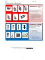
1
SCORPION MAGNETIC DRILLING
MACHINE
Model No. CM/500/1 CM/500/3
This machine (Serial No
) is CE approved.
Rotabroach Ltd
Imperial Works, Sheffield Road
Sheffield, South Yorkshire
United Kingdom
S9 2YL
Tel: +44 (0) 114 2212 510
Fax: +44 (0) 114 2212 563
Email: [email protected] Web site: www.rotabroach.co.uk
Issue 3
March 2011
Other products by Rotabroach.
For more information please visit our website at www.rotabroach.co.uk
Or contact our sales department on +44 (0) 114 2212 510
2
Issue 3
March 2011
CONTENTS OF THE MANUAL.
Page
[1]
[2]
[3]
[4]
[4.1]
[4.2]
[5]
[6]
[7]
[8]
[9]
[10]
[11]
[12]
[12]
General Safety
Specification of machine.
Operational safety procedures.
Operating instructions.
Operating Panel
Speed and Torque setting.
Mounting of cutters
Remedies for hole making problems
Arbor attachments
Exploded view and component parts of complete machines.
Exploded view and component parts of gearbox and motor units.
Maintenance checks
Trouble shooting
Cutter Selection, Speeds and feeds
Warranty
3
4
5
6
7
8
9
10
10
11
12
13
14
16
17
20
Issue 3
March 2011
[1] GENERAL SAFETY RULES
WARNING! When using electric tools basic safety precautions should always be followed to reduce the risk of fire, electric shock and
personal injury, including the following.
Read all these instructions before attempting to operate this product
Remove the power supply before carrying out any adjustment, serving or maintenance.
1.
2.
3.
4.
5.
6.
7.
8.
9.
10.
11.
12.
12.
13.
15.
16.
17.
18.
19.
20.
21.
22.
Keep work area clear cluttered areas and benches invite injuries.
Consider work area environment
•
Do not expose tools to rain.
•
Do not use tools in damp or wet locations.
•
Keep work area well lit.
•
Do not use tools in the presence of flammable liquid or gases.
Guard against electric shock
Avoid body contact with earthed or ground surfaces (e.g. pipes, radiators, cookers and refrigerators). Electric safety can be further
improved by using a high-sensitivity (30 m A/0.1s) residual current device (RCD).
Keep other persons away do not let persons, especially children, not involved in the work touch the tool or the extension cord and keep
them away from the work area.
Store idle tools when not in use, tools should be stored in a dry locked-up place, out of reach of children.
Do not force the tool it will do the job better and safer at the rate for which it was intended.
Use the right tool
•
Do not force small tools to do the job of a heavy duty tool.
•
Do not use tools for purposes not intended: for example do not use circular saws to cut tree limbs or logs.
Dress properly
•
Do not wear loose clothing or jewellery; they can be caught in moving parts.
•
Non-skid footwear is recommended when working outdoors.
•
Wear protective hair covering to containing long hair.
Use protective equipment when using this machine
•
Use safety glasses.
•
Use ear defenders.
•
Use face or dust mask if cutting operations create dust.
•
Use protective gloves
Connect dust extraction equipment if device are provided for the connection of dust extraction and collecting equipment, ensure these
are connected and properly used.
Does not abuse the cord; never pull the cord to disconnect it from socket. Keep the cord away from heat, oil and sharp edges.
Secure work where possible use clamps or a vice to hold the work. It is safer than using your hand.
Do not overreach keep proper footing and balance at all times.
Maintain tools with care
•
Keep cutting tools sharp and clean for better and safer performance.
•
Follow instruction for lubricating and changing accessories.
•
Inspect tool cords periodically and if damaged have them repaired by an authorized service facility.
•
Inspect extension cords periodically and replace if damaged.
•
Keep handles dry, clean and free oil and grease.
Disconnect tools when not in use, before servicing and when changing accessories such as blades, bits and cutters, disconnect tools
from the power supply.
Remove adjusting keys and wrenches form the habit of checking to see that keys and adjusting wrenches are removed from the tool
before turning it on.
Avoid unintentional starting ensure switch is in “off” position when plugging in.
Use outdoor extension leads when the tool is used outdoors, use only extension cords intended for outdoor use and so marked.
Stay alert watch what you are doing, use common sense and do not operate the tool when you are tired.
Check for damaged parts before further use of tool; it should be carefully checked to determine that it will operate property and its
intended function.
Warning! The use of any accessory or attachment other than one recommended in this instruction manual may present a risk of
personal injury.
Have your toll repaired by a qualified person
This electric tool complies with the relevant safety rules. Qualified persons using original spare parts should only carry out repairs;
otherwise this may result in considerable danger to the user.
4
Issue 3
[2]
March 2011
SPECIFICATION
Maximum hole cutting capacity in .2/.3C steel = 100mm dia. x 75mm deep optional 100mm
Arbor bore = 19.05mm (3/4") dia.
Motor Unit
Voltages
normal full load
Electro Magnet
Size
18 A
0.35A
Tractive Force at 20°C with 25mm
minimum plate thickness
The use on any material less than 25mm thick will progressively
reduce the magnetic performance. If possible, substitute material
should be positioned under the magnet and work piece to equate to a
suitable material thickness. If this is not possible, an alternative
secure method of restraining the machine MUST be used.
Overall Dimensions
Height - maximum extended
Height - minimum
Width (including Hand wheel)
Length Overall (including Guard)
Nett Weight
Stroke
Maximum hand/arm vibration magnitude (measured at handle during
operation in accordance with ISO5349, using a 22mm cutter through
13mm MS plate)
Estimate of likely daily vibration exposure. Operation 30 holes @ 2
minute/hole.
110v
230v
1800 W
9A
1800 W
69W
0.35A
69W
230mm long
100mm wide
3000kgs
708mm
453mm
190mm
340mm
26kgs
255mm
2,5 m/s²
0,8 m/s²
Ear defenders and Eye protection must be worn when operating this machine.
These tools are designed, and manufactured with globally sourced components and conform with the
requirements of EEC Document HD.400.1 and BS.2769/84
Suitable only for a single phase 25-60Hz A.C. power supply
DO NOT USE ON D.C. SUPPLY
Do not use your magnetic drill on the same structure when arc welding is in progress. D.C. current will
earth back through the magnet and cause irreparable damage.
WARNING: THIS APPLIANCE MUST BE EARTHED!
NB: ANY MODIFICATIONS TO THIS MACHINE WILL INVALIDATE THE GUARANTEE
List of Contents with Magnetic Drill Unit
RD46111
RD40525
RD46112
RD40080
RD4153
RD4230
CA13100
RD46113
Carry Case
Safety Chain
Drift
2.5mm Allen Key
5mm Allen Key
6mm Allen Key
3MT Arbor attachment
Coolant Bottle
5
Check
List
YES/NO
YES/NO
YES/NO
YES/NO
YES/NO
YES/NO
YES/NO
YES/NO
Issue 3
March 2011
READ BEFORE USING THE MACHINE
[3]
•
•
•
•
•
•
•
•
•
•
•
•
•
•
•
•
•
•
OPERATIONAL SAFETY PROCEDURES
The CM/500 is specifically designed for drilling holes/ Tapping/ Reaming and
countersinking in steel. The CM/500 may not be adapted and/or used for applications
other than those it has been designed for.
When using electrical tools, basic safety precautions should always be followed to reduce
the risk of electric shock, fire, and personal injury.
Do NOT use in wet or damp conditions. Failure to do so may result in personal injury.
Do NOT use in the presence of flammable liquids or gases. Failure to do so may result in
personal injury.
ALWAYS SECURE THE MACHINE WITH THE SAFETY CHAIN BEFORE
STARTING TO OPERATE - for the user's protection in case of power failure or the
magnet's breaking loose whilst in use. Failure to do so may result in personal injury.
ALWAYS WEAR APPROVED EYE AND EAR PROTRCTION WHEN THE
EQUIPMENT IS IN OPERATION. Failure to do so may result in personal injury.
Disconnect from the power source when changing cutters, Arbors or working on the
machine.
When changing cutters, or removing swarf, ALWAYS wear approved gloves.
ALWAYS ENSURE CUTTER RETAINING SCREWS ARE SECURE - they sometimes
vibrate loose when the machine is in continuous use.
Regularly clear the work area and machine of swarf and dirt, paying particular attention
to the underside of the magnet base.
With a gloved hand, and after switching off, remove any swarf which might have
gathered around the cutter and arbor before proceeding with the next hole.
Before operating the machine, always remove tie, rings, watches and any loose
adornments which might entangle with the rotating machinery. Failure to do so may result
in personal injury.
Should the cutter become 'fast' in the work piece, stop the motor immediately to prevent
personal injury. Disconnect from the power source and turn arbor to and fro. DO NOT
ATTEMPT TO FREE THE CUTTER BY SWITCHING THE MOTOR ON AND OFF.
If the machine is accidentally dropped, always thoroughly examine the machine for signs
of damage and check that it functions correctly before trying to drill a hole.
Regularly inspect the machine and check that nuts and screws are tight.
Always ensure when using the machine in an inverted position that only the minimum
amount of coolant is used or use suitable cutting paste. Care is to be taken to ensure that
coolant does not drip on to the motor unit.
Cutting tools may shatter; always ensure that you are wearing appropriate eye protection
before activating the machine. Failure to do so may result in personal injury.
On completion of the cut, a slug will be ejected. DO NOT operate the machine if the
ejected slug may cause injury.
6
Issue 3
March 2011
[4] OPERATING INSTRUCTIONS
•
•
•
•
•
•
•
•
•
•
•
•
•
•
•
Keep the inside of the cutter clear of swarf. It restricts the operating depth of the cutter.
Ensure that the coolant bottle contains sufficient cutting oil to complete the required operating
duration. Refill as required.
Occasionally depress the pilot to ensure cutting fluid is being correctly metered.
To start the machine, first switch on the magnet by turning the rocker switch to position <1>.
Then start the motor by depressing the GREEN start button.
ALWAYS switch off the motor by depressing the RED stop button. DO NOT switch off the
motor by pressing the magnet switch to zero.
Always ensure both magnet coils are on the work surface. Incorrect adhesion will result in poor
holding force.
Always ensure that there is a least 10mm thickness of material for the magnet to adhere to for the
magnet to work best.
Do not connect any other machines to the electrical outlet the drill is plugged into, as this may
result in the loss of magnetic force.
Apply light pressure when commencing to cut a hole until the cutter is introduced into the work
surface. Pressure can then be increased sufficiently to load the motor. Excessive pressure is
undesirable, it does not increase the speed of penetration and will cause the safety overload
protection device to stop the motor, (the motor can be restarted by operating the motor start
button), and may cause excessive heat which may result in inconsistent slug ejection
Always ensure that the slug has been ejected from the previous hole before commencing to cut the
next.
If the slug sticks in the cutter, move the machine to a flat surface, switch on the magnet and gently
bring the cutter down to make contact with the surface. This will usually straighten a cocked slug
and allow it to eject normally.
Apply a small amount of light oil lubricant regularly to slide and arbor support bearing.
Cutter breakage is usually caused by insecure anchorage, a loosely fitting slide or a worn bearing
in the arbor support. (Refer to routine maintenance instructions).
Only use approved cutting fluid. Rotabroach cutting fluid has been specially formulated to
maximise the cutters performance. It is available in 1 litre (RD208), 5 litre (RD229), and 25 litre
(RD220) containers.
When using the machine drill vertically or upside down, avoid metal burrs from getting into the
unit. We will not repair any damage done to the machine by such action under the coverage of our
warranty.
7
Issue 3
March 2011
[4.1] THE CONTROL PANEL
3
5
1
2
4
1. The magnet indicator.
This indicator shows if the magnet is working effectively. The indicator light turns green if
there is sufficient magnetic force. If it lights up red the magnet is not generating sufficient
attachment force. Note this is only an indicator and not a certainty that the magnet will not
release the material. Rotabroach accepts no liability ensuing from the magnet indicator not
functioning or functioning poorly.
2. The forward / reverse switch.
This rocker switch is used to determine the direction of rotation of the electric drill.
3. The Motor Switch
This switch is used to turn the motor on or off.
4. The fuse holder.
Houses a 2 Amp glass fuse 5x20.
5. The Magnet Switch.
To turn the magnet on and off. This needs to be on before the motor switch can work
[4.2] Speed and Torque adjustment.
Gear Selection – Gear positions when seen facing the machine
Gear Selection
Speed
Setting
1
2
3
4
5
1
70
82
103
144
199
2
3
241
279
355
494
670
45
52
64
89
124
4
150
171
216
303
416
Gear selection should vary depending on the size of
the cutter used. For small cutters gear selection 2
should be used. From 30mm – 60mm gear 4 should
be used. From 60 – 80mm gear 1 should be used and
from 80mm+ use gear 3.
8
Issue 3
March 2011
1
2
SPEED SELECTION (1)
The machine is equipped with 4 gear ranges which can produce speeds up to 100,
175, 245 and 385 rpm. Do not change the gear while the motor is in motion.
The speed range for this gear is changed by the rotary change switch located on the gearbox
side.
Speed controller
(Blue)
Gear Selection
The speed controller is adjusted by rotating the blue disk located on the side of the
motor there are 5 speed settings which can be used.
Before cutting holes the work piece ensure that you are using the correct speed and
gear for your material and cutter. Site conditions, e.g. diameter and condition of cutter,
material condition, material thickness, etc must also be taken into account when determining
the suitable cutting speed. The speed and feed rate must continuously be monitored and
adjusted to ensure optimum cutting conditions prevail.
In general the faster output speeds would be used for smaller cutters and the slower more
torque gears for larger cutters.
TORQUE ADJUSTMENT (2)
The CM/500 is also fitted with a variable torque control which can alter the torque of
the motor electronically. This reduces or increase the motors electronic cut off point so that
more or less current can be drawn by the motor before it cuts off. For smaller cutters this
should be set to a low range, for larger cutters this should be set high.
Torque controller
(Red)
9
Issue 3
March 2011
ALWAYS DISCONNECT THE MACHINE FROM THE POWER SOURCE WHEN
CHANGING CUTTERS.
[5]
MOUNTING OF CUTTERS
The machine has been made to accept cutters having 19.05mm (3/4") dia. shanks
The following procedure is to be used when mounting cutters.
Take appropriate pilot and place through hole in shank of cutter. Insert shank of cutter into
3/4" dia. bore of arbor, ensuring alignment of two drive flats with socket screws
Tighten both screws using hexagon key 5mm.
[6] REMEDIES FOR HOLE MAKING PROBLEMS
Problem
1) Magnetic base
won’t hold
effectively
2) Cutter skips
out of centrepunch mark at
initiation of cut
Cause
Material being cut may be too thin for efficient
holding.
Remedy
Attach an additional piece of metal under work-piece where
magnet will be located, or mechanically clamp magnetic base to
work-piece.
Swarf or dirt under magnet.
Clean magnet.
Irregularity on magnet contact or work-piece.
Use extreme care; file any imperfections flush to surface.
Insufficient current going to magnet during drilling
cycles.
Magnetic base is not holding effectively.
Confirm power supply and output from control unit, check
supply cable.
See causes and remedies above.
Worn arbor bushing and/or ejector collar.
Replace! Only a few thousandths wear permissible. New arbor
bushing is needed.
Light pressure only is needed until a groove is cut. The groove
then serves as a stabilizer.
Too much feed pressure at start of cut.
3) Excessive
drilling pressure
required
4) Excessive
cutter breakage
5) Excessive
cutter wear
Cutter is dull, worn, chipped or incorrectly sharpened.
Replace or re-sharpen. Sharpening service is available.
Poor centre-punch mark; weak pilot spring; pilot not
centred in centre-punch mark.
Improve centre-punch and/or replace worn parts
Worn or bent pilot, worn pilot hole.
Replace part or parts
Loose bolts on motor bushing support bracket, main
casting or loose gib adjusting set screws.
Incorrectly re-sharpened, worn or chipped cutter.
Adjust where necessary
Coming down on swarf lying on surface of workpiece.
Take care not to start a cut on swarf.
Gibs out of adjustment or lack of lubrication.
Adjust setscrews, and lubricate.
Swarf accumulated (packed) inside cutter.
Steel swarf or dirt under cutter.
Clear cutter.
Remove cutter, clean part thoroughly and replace.
Incorrectly re-sharpened or worn cutter.
Always have a new cutter on hand to refer to for correct tooth
geometry, together with instruction sheet.
Cutter skipping.
See causes and remedies (2).
Slide-ways need adjustment.
Tighten sideway.
Cutter not attached tightly to arbor.
Retighten.
Insufficient use of cutting oil or unsuitable type of
oil.
Inject oil of light viscosity into the coolant-inducing ring and
check that oil is being metered into cutter when pilot is
depressed. If not, check pilot groove and arbor internally for dirt
or apply oil externally. (Even a small amount of oil is very
effective).
Re-sharpen or replace.
See cause and remedy above
Incorrectly re-sharpened cutter.
Refer to instructions and a new cutter for proper tooth geometry.
Insufficient or spasmodic cutting pressure.
Use sufficient steady pressure to slow the drill down. This will
result in optimum cutting speed and chip load.
10
Issue 3
March 2011
[7] ARBOR ATTACHMENTS
The CM/500 has been design so that a number of 3 morse taper attachments can be used with
this machine.
Arbors for cutters
Currently available from Rotabroach are a number of various Arbors for fitting our range of
cutters that are available with the standard 19.05mm Weldon shank attachment and also are
available with a 32mm Weldon shank.
Twist drills
It is possible to also use twist drills with this machine. These can either be 3MT twist drills or
a using a suitable drill chuck. Please contact our sale department for further details. Max size
twist drill that can be used with this machine is 32mm.
Tap and Tap holders
Again as with the Twist drills this machine can also allow you to tap through holes. Using a
suitable tap or tap holder they can be connected to the 3MT output shaft.
The machine is suitable for tapping up to M30. Please contact our sales department for
further details and our available products.
11
Issue 3
March 2011
[8] EXPLODED VIEW OF COMPLETE MACHINE
26
34
22
27
Item
Part No.
Component
Qty
Item
24
Part No.
RD46223
Component
Magnet Spring ball screw
Qty
1
1
RD3638
Housing
1
25
RD4502
Information plate
1
2
RD4613
Screw M8 x 25
3
RD4614
Washer M8
4
26
RD4637
Motor Cable
1
4
27
RD4634
Connector
4
RD4615
2
Nut M5
7
28
RD4635
Mains cable fixing
1
5
6
RD46215
Setting screw
7
29
RD4636
Mains cable complete
1
RD46216
Magnet
1
30
RD46224
Screw Nut Washer for Earthing
7
RD46217
Sensor
1
31
RD4638
M4 x 8 Panel screw
4
32
RD3642
Front Plate 110V
1
RD3639
Front Plate 230V
1
8
N/A
9
RD46218
Slide
1
33
RD46225
LED Indicator
1
10
RD46219
Rack
1
34
RD4640
Motor On/ off Switch
1
35
RD4641
Fuse Holder
1
11
RD4620
M6 x 55 Screw
2
36
RD4642
Fuse 20 x 5 F2A
1
12
RD4621
Motor Holder
1
37
RD4643
Magnet Switch
1
13
RD46220
M6 x 30 Screw
1
38
RD4644
L/R switch
1
14
RD4623
M6 x 16 Screw
4
39
RD4645
Control Unit 110V
1
15
RD46221
GIB strip
1
RD4646
Control Unit 230V
1
16
RD46222
Adjustment plate
1
40
RD46226
Panel Plate assembly
17
RD4626
Capstan Hub assembly
1
41
RD46227
Motor Unit 230V 1800W
1
18
RD4627
End Plate
1
RD46228
Motor Unit 110V 1800W
1
19
RD4628
M6 x 20 End Screw
1
42
RD4649
Top Plate
1
20
RD4629
Capstan Arm
3
43
RD4650
Screw for top plate
2
21
RD4630
Motor fixing top
1
44
RD3640
Carry Handle
1
22
RD4631
M8 x 35 Screw
2
45
RD3641
Name Plate
1
23
RD4632
Magnet Spring ball
2
Issue 3
Original Version
March 2011
[9] EXPLODED VIEW OF
GEARBOX AND MOTOR UNITS
Item
Part No.
Component
Qty
Item
Part No.
Component
Qty
51
RD46229
Screw
4
83
RD46264
Neadle bearing
1
52
RD46230
Screw
4
84
RD46265
Washer
1
53
RD46231
Armature assembly (230v)
1
85
RD46266
Double gear 1
1
53
RD46232
Armature assembly (110v)
1
86
RD46267
Key
1
54
RD46233
end cover
1
87
RD46268
Axle 2
1
55
RD46234
Screw
2
88
RD46269
Bearing
1
56
RD46235
Speed Control Unit 230V
1
89
RD46270
Axle 3 13T
1
56
RD46236
Speed control Unit 110V
1
90
RD46271
Clutch shaft 2 (L-type)
1
57
RD46237
Rubber fitting Ring
1
91
58
RD46238
Washer
1
92
RD46272
Key 3 (L)
1
59
RD46239
Armature speed disk
1
93
RD46273
Plate for Gear Casing
1
60
RD46240
Bearing
1
94
RD46274
Clutch shaft 1
1
61
RD46241
Carbon brush
2
95
RD46275
Gear switch
1
62
RD46242
Friction Clutch Complete
1
96
RD46276
First gear
1
63
RD46243
Carbon brush assembly
2
97
RD46277
Cylinder
1
64
RD46244
Field coil 110v
1
98
RD46278
Shell 25
1
64
RD46245
Field coil 230v
1
99
RD46279
Nut
1
65
RD46246
Motor housing
1
99A
RD46280
Washer
1
66
RD46247
Baffle
1
99B
RD46281
Friction Disk 1
1
67
RD46248
Inner Gear Plate
1
99C
RD46282
Brass Disk 1
1
68
RD46249
Gasket
1
99D
RD46283
Brass Disk 2
1
69
RD46250
Needle bearing
1
99E
RD46284
Friction Disk 2
1
70
RD46251
Double Gear 2
1
100
RD46285
Shell 28
1
71
RD46252
Axle 1
1
101
RD46286
Circlip
1
72
RD46253
Circlip
1
102
RD46287
Bearing
1
73
RD46254
Key spindle
1
103
RD46288
Circlip
1
74
RD46255
Spindle gear (38T)
1
104
RD46289
T/S Switch housing Red/Blue
1
75
RD46256
adaptor ring
1
105
RD46290
T/S Switch Cover
1
76
RD46257
Bearing
1
106
RD46291
Speed Potentiometer 100K
1
77
RD46258
Circlip
1
107
RD46292
Torque Potentiometer 1K
1
78
RD46259
Gear Casing
1
108
RD46293
Red wheel
1
79
RD46260
Spindle Drive shaft
1
109
RD46294
Blue wheel
1
80
RD46261
Bearing
1
110
RD46295
Casing Pin
1
81
RD46262
Circlip
1
111
RD46296
Screw 6 x 45
4
82
RD46263
adaptor ring
1
112
RD46297
T/S Switch Housing complete
1
13
Issue 3
Original Version
March 2011
[10] Tips for keeping your machine in correct working order.
In order to ‘get the best life’ out of your Rotabroach machine always keep in good
working order. A well maintained machine is a happy machine.
A number of items must always be checked on Rotabroach machines.
Always before starting any job make sure the machine is in good working order and that
there are no damaged or loose parts. Any loose parts must be tightened.
Before proceeding with any maintenance work be certain that the power supply is
disconnected.
Description
Visual check of
machine for
damage
Operation of
machine
Check brush wear
Check magnetic
base
Check alignment of
the machine
Check grease
Check Armature
Every operation 1 week
1 Month
X
X
X
X
X
X
X
Visually check the machine for damage.
Machine must be checked before operation for any signs of damage that will affect the
operation of the machine. Particular notice must be taken of the mains cable, if the
machine appears to be damaged it should not be used failure to do so may cause injury
or death.
Check operation of the machine.
The machines operation must be checked to ensure that all components are working
correctly.
Machine Brushes - should be checked to make sure there is no abnormal wear present
this should be checked at least once a week if used frequently. If the brush has worn
more than 2/3 the original length the brushes should be changed. Failure to do so may
cause damage to the machine.
Magnetic base – before every operation the magnetic base should be checked to make
sure that the base is flat and there is no damage present. An uneven magnet base will
cause the magnet not to hold as efficiently and may cause injury to the operator.
14
Issue 3
Original Version
March 2011
Adjustment of slide and bearing bracket Alignment.
An essential requirement of the machine is that the slide can move in a smooth and
controlled manner, free of lateral movement and vibration.
This situation can be maintained by periodic adjustment of the slide and is accomplished
in the following manner:
1. Place the machine in an upright position and, by means of the capstan, raise the
slide to its highest position. Clean the brass gib strips and apply a small amount
of light machine oil to the wear surfaces.
2. Now lower the slide back to its lowest position. Bring the slide into the centre of
the dovetail slide housing and loosen screws thus allowing free movement of the
arbor support bracket.
3. Commencing with the middle screws, gently feed in all the screws until slight
resistance is encountered.
4. Operate the slide up and down a few times to test the movement and make any
further necessary adjustments. Try to ensure that all the screws are exerting a
uniform pressure on the slide from top to bottom. A perfectly adjusted slide will
operate freely up and down without any sideways movement.
5. Now raise the slide to its highest position.
6. Place the machine on a steel plate, connect to supply and switch on magnet.
Start up the motor. If the arbor is incorrectly aligned, the arbor support bracket
will be seen to oscillate. Make any necessary further adjustments to the bracket
to ensure correct alignment of the spindle and finally tighten the screws using a
spanner.
Check machines grease.
The gearbox grease should be checked once a month to ensure all moving components
are covered to prevent wear. The grease should be changed at least once a year to
ensure you gain the best from the machine.
Check Armature of the machine.
This should be checked at least 1 per month to check that there are visual signs of
damage to the body or to the commutator. Some signs of wear will be seen on the
commutator over a period of time this is normal as this is the part that comes in contact
with the brushes but any signs of abnormal damage and the part should be replaced.
15
Issue 3
Original Version
[11] TROUBLE SHOOTING
Magnet and motor do not function
Magnet does function, the motor does not
Magnet does not function, the motor does
Hole cutters break quickly, holes are bigger
than the hole cutter
Motor running roughly and/or seizing up
Motor making a rattling sound
Motor humming, big sparks and motor has no
force
Motor does not start or fails.
Guiding takes a great deal of effort
Insufficient magnetic force
Motor only runs at maximum rpm
Frame under voltage
Fuse blows when magnet switch is turned on
Fuse blows when motor is started up
Rotation system free stroke too long
- The magnet switch is not connected to the power supply
- Damaged or defective wiring
- Defective fuse
- Defective magnet switch
- Defective Control Unit
- Defective power supply
- Damaged or defective wiring
- Carbon brushes are stuck or worn out
- Defective magnet switch
- Defective On / off switch
- Defective Control Unit
- Defective armature and/or field
- Defective magnet protective switch
- Defective magnet
- Defective Control Unit
- Play in the guide
- Bent spindle
- Defective Magnet causing movement
- Shaft extending from the motor is bent
- Uneven work surface causing lack of magnetic adhesion.
- Bent pilot
- Bent spindle
- Shaft extending from the motor is bent
- Triangular guide not mounted straight
- Dirt between spindle and triangular guide
- Gear bearing (bottom of the armature) worn out
- Gear(s) worn out
- No grease in gear box
- Armature burned
- Field burned
- Carbon brushes worn out
- Damaged or defective wiring
- Dirt in sensor of Speed Control Unit
- Defective Speed Control Unit
- Defective speed control or its wiring
- Defective or loose magnet on top of armature
- Damaged or defective brushes
- Guide is set too tight
- Guide is dry
- Guide/gear- rack/rotation system dirty or damaged
- Damaged or defective wiring
- Bottom of magnet not clean and dry
- Bottom of magnet not flat
- Work piece is not bare metal
- Work piece is not flat
- Work piece is too thin less than 10mm
- Defective Control Unit
- Defective magnet
- Defective speed switch
- Damaged / defective wiring
- Defective Control Unit
- Damaged / defective wiring
- Defective magnet
- Motor seriously dirty
- Damaged or defective wiring
- Wrong value fuse
- Defective magnet switch
- Defective Control Unit
- Defective magnet
- Damaged or defective wiring
- Wrong value fuse
- Motor running roughly
- Defective Armature and / or Field
- Carbon brushes worn out
- Defective Control Unit
- Loose or defective gear-rack
- Defective rotation system
16
March 2011
Issue 3
March 2011
[12] Cutter selection, Speeds and Feeds
17
Issue 3
March 2011
Notes:
18
Issue 3
March 2011
Notes:
19
Issue 3
March 2011
WARRANTY STATEMENT
Rotabroach® warrants its machines to be free from faulty materials, or workmanship under normal use for a
period of 6 months from initial date of purchase and 90 days for all other parts (excluding cutters), provided
that the warranty registration card (or online registration) has been completed and returned to Rotabroach®,
or its designated distributor within a period of (30) days from the purchase date, failure to do so will void the
warranty. If the stated is adhered to Rotabroach® will repair or replace (at its option) without charge any
faulty items returned.
This Warranty does not cover:
1. Components that are subject to natural wear and tear caused by the use in accordance with the operators instructions
2. Defects in the tool caused by non-compliance with the operating instructions, improper use, abnormal environment conditions,
inappropriate operating conditions overload or insufficient servicing or maintenance.
3. Defects caused by using accessories, components or spare parts other than original Rotabroach® parts.
4. Tools to which changes or additions have been made.
5. Electrical components are subject to manufacturer’s warranty.
Your online registration can be submitted on www.rotabroach.co.uk
The warranty claim must be lodged within the warranty period. This requires the submission or sending of
the complete tool in question with the original sales receipt which must indicate the purchase date of the
product. A complaint form must also be submitted prior to the return.
This can be found online at www.rotabroach.co.uk Failure to complete this form will result in the delay of
your claim.
All goods returned defective must be returned pre-paid to Rotabroach®, in no event shall Rotabroach® be
liable for subsequent direct, or indirect loss or damage.
THIS WARRANTY IS IN LIEU OF ANY OTHER WARRANTY,
(EXPRESSED OR IMPLIED) INCLUDING ANY WARRANTY OF
MECHANTABLITY OR FITNESS FOR A PARTICULAR PURPOSE.
ROTABROACH® RESERVE THE RIGHT TO MAKE IMPROVEMENTS
AND MODIFICATIONS TO DESIGN WITHOUT PRIOR NOTICE
Known and Trusted Worldwide for Quality, Performance and Reliability
20