1
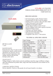
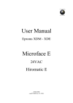
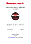
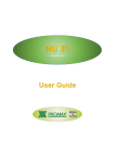
www.electrosec.com
electrosec
R
GD-USB
GSM DIALER, FCT &
MULTI SMS UNIT
USER’S MANUAL
FEATURES
Continuous Communication with Landline and GSM lines
to AMS (Alarm Monitoring Station) & SMS sending
Transfer via GSM data & SMS during landline failure
Quad Band 800-900-1800-1900 Mhz. GSM module
Detailed SMS sending; including message title,
Alarm event, Alarm users name and Alarm zone name
Convert to event transfer SMS, for all alarm units with
ADEMCO contact ID format, either with or without
AMS connection or disconnection
Send emergency SMS button, JAMMER alarm output
FCT unit compatible for all types of internal phone unit
High Speed 2.0 USB computer input
Windows XP-VISTA compatible
Automatic software upgrade on internet
MULTI SMS sending via PC control software
Read incoming SMS via PC control software
2x16 large screen, blue backlight LCD
Detailed English language program menu
Stainless steel metal case, 12Vdc. input 500 mA.
Dimensions : 285 x 128 x 52mm, Weight: 980 Gr
TECHNICAL SPECIFICATIONS
Input voltage
Current (St-by)
Current (Active)
GSM Modul Band
Gsm Band Sensitive
Gsm Band Sensitive
FCT Ring Voltage
FCT Subscriber Line Voltage
Lcd Screen
Programmable
PC. Input
Cable Connections
Thermal Protection
Operating Temperature
Case Dimension
Weight
Antenna Dimension
2009-1 electrosec
:
:
:
:
:
:
:
:
:
:
:
:
:
:
:
:
:
12-18 Vdc.
100 mA.
400 mA.
Quad 850,900,1800,1900 MHz.
850-900 Mhz. Typ. 107dBm.
1800-1900 Mhz. Typ.106 dBm.
75 Vac. 100 mA. 25Hz.
48Vdc. 100 mA.
2x16 LCD Blue screen
Via Subscriber line
Full Speed USB 2.0
Screw Type Socket
+ 125 C
-20 + 60 °C
285 x 128 x 52mm.
980 Gr.
5 cm. or 3mt. with cable
Page 1/6
GD-USB User’s manual
CONNECTION DIAGRAM
SIMPlus
Pull back the
plastic slot on
pcb and lift up & insert your GSM sim card
than push the slot back
12 Vdc. 1A.
Regulated adapter
or power supply
of alarm panel
JAMMER Open
collector
alarm
output Norm. (-)
Emergency
SMS button
+
-
CONNECTIONS
FROM
LEFT to RIGHT
Landline or
internal phone
central line output
1-) + 12 Vdc.
2-) - (gnd.)
3-) Landline or internal line input (Tip)
4-) Landline or internal line input (Ring) Landine or
internal phone
5-) Landline or internal line output (Tip)
central line output
6-) Landline or internal line output (Ring)
7-) Subscriber line output (Tip)
8-) Subscriber line output (Ring)
9-) Emergency SMS button input (- trigger)
10-)JAMMER alarm output (Open coll. normaly -)
--
GSM Dialer
Connectable
alarm panel
line input
FCT Unit
Connectable
internal phone
central line input
Connectable phone
for programming
Full speed
USB 2.0
ISOLATION CARD CONNECTION DIAGRAM
If GD-USB Gsm module will
be connected to a dialer unit
(VD-2005, TD-200 etc)
using an isolation card
is recommended.
Connection diagram
is on the right.
2009-1 electrosec
To Dialer
Line input
Page 2/6
GD-USB User’s manual
PROGRAMMING
To program , after inserting the SIM card, connect a basic telephone to connector no 7-8,
considering the polarisation link the power supply to connector no 1-2 as shown in page 2.
In this case there should not be a link with connectors no 3 and 4. Otherwise the unit will not be in
programming mode. After you make sure the unit is in the programming mode please connect the
power supply to power point.
The following will appear on screen as it turns on.
EKO
AT E 0 O K
S I M CART
YES
PI N
CONTROL
YES
PI N
CHECK?
TRU E
This command indicates the GSM module is working properly..
If the unit does not proceed to command 2 after 1 second. There is
a problem in the GSM module. Please contact your authorised agent.
Test the SIM card in the GSM module. If the SIM card is inserted
you will see a YES sign on the second line. If you see NO sign on the
second line please check the SIM card again and turn off the unit.
This command line checks if the SIM card has a PIN
code. If there is not a PIN code you will see NO on
the screen and move to the next step
This command checks the PIN code. If you see
FALSE please enter the correct PIN code for
the SIM card in menu 3
Please do not consider the other commands until you reach the screen shot below.
They are for system tests.
GD - USB
GSM D IA LER
This main screen will appear after the commands. On the left hand side of
the screen you will see 3 different digits indicating 3 different situations.
1- If everyting is normal an antenna display level chart will appear, increasing from left to right,
If the unit is not in the GSM coverage area the chart will be empty and will flash. In this case
please change the place of the unit or use an antenna extension.
P
2- If you see this symbol flashing SIM card PIN code is not correct. In this case
pleae enter the correct PIN code from 3 menu and turn off the unit and then turn
it on again.
3- If you see this symbol flashing SIM card is not inserted correctly. In this case please
make sure the SIM card is inserted correctly and the SIM socket is locked and turn off
the unit and then turn it on again.
2009-1 electrosec
Page 3/6
GD-USB User’s manual
The two different digits on the right hand side of the graphic
indicates the external line or GSM line.
GD - USB
GSM D IAL ER
1- If you see this symbol on the grapfic it means connectors 3 and 4 has a connection
failure. In this case system calls will be made through GSM line. When the connection
is active the symbol flashes.
2- If you see this symbol on the grapfic it means connectors 3 and 4 has a connection
failure. In this case system calls will be made through this line. When the connection
is active the symbol flashes.
PROGRAM MENUS
*
After you make sure there is a no link in connectors 3 and 4 pick up the telephone and press
‘Program’ menu will appear on screen. Use 1-9 keys to enter program menus. Properties of a
menu will be deleted if you enter with. To save use #
The details of menus 1-9 are as follows:
*
* 1 Area Code : This menu is very important for the system to work properly. Suppose the
GSM dialer is connected to an Alarm Station and the telephone number 2120310 is entered for
the AHM. When there is no connection failure the GSM dialer will communicate without any
problem. But when there is an external line failure, the unit will dial the same number from
GSM line the telephone number will be incomplete. This is why the area code must be entered
in the menu. If there is already a number with 11 digits is entered (0312xxxxxxx) in the Alarm
Station then there is no need enter the area code in this menu.
* 2 Extension Number : Suppose that GSM Dialer unit is connected to an Alarm Station,
one of the users internal line is used as an external line and telephone number 92120310 is
entered in the Alarm Station. ( 9 at the beginning is for exit code ) GSM dialer unit will
communicate without any problem as long as there is an external line. But the number will be
imcomplete if the unit dials the same number via GSM line. This is why a number for exit code
must me entered in the Alarm Station.
* 3 PIN CODE : If there is a PIN Code assinged to the SIM card, please enter the
PIN code using this menu.
2009-1 electrosec
Page 4/6
GD-USB User’s manual
* 4 Message Title : GD- USB unit is a professional device analysing the data between AMS
and Alarm Station.The result of this data analysis can be sent to a telephone number via SMS if
desired. To see the source of these SMS messegas 16 digit information can be entered using this
menu. Factory settings show GSM Dialer Unit by default.You may change this if you desire.
Use keys 1-9 to enter alphanumeric characters. If alphanumeric characters are not avaliable on
the telephone, you may get help by checking the keys of a mobile phone.
* 5 User Name : With this menu Alarm Users names are entered . It is important as the user
names will appear on the SMS messages.Maximum 9 different users can be entered.Following
key 5 the user no is entered.Factory settings are name—0X Maximum 8 characters can be
entered. Please enter the same directions for Messege Header for this menu as well.
* 6 Area Name : With this menu Area Names used in the Alarm are entered. It is important as the
area names will appear on the SMS messages.Maximum 9 different areas can be entered.
Following key 6 the area name is entered. Factory settings are area—0X Maximum 8 characters
can be entered. Please enter the same directions for Messege Header for this menu as well.
* 7 GSM Number : With this menu the GSM numbers for sending SMS messeges are set.
Maximum 3 different GSM numbers can be entered. Following key 7 the sequence number
is set and entered. On the right hand side of the screen lat 2 digits appear –X . Maximum
14 characters can be entered.After entering each number a digit will move right automatically.
The important point here is to enter the country code at the beginning of each GSM number.
For example : if you want to enter GSM no 05332364947 , you must enter 905332364947.
SMS messages will be sent starting from line 1.
* 8 AMS Control : This menu is designed assuming the GSM dialer is not connected to an
Alarm Station not connected to an AMS. In this case GSM Dialer will send the information
via SMS, to the GSM numbers assinged in Menu 7 , instead of an AMS. Uses International
Ademco Contatc ID format. Factory settings are set as 2-Disabled. To turn on this feature
enter 1-ON and Alarm station connected must contain a 7 digit telephone number and
4 digit Customer Number in the AMS menu.
* 9 SMS sending : With this menu you can set the GSM dialer to send SMS or not.
Factory settings are set as 1-ON. To turn off this feature and stop the unit to send SMS,
enter 2-Disabled
* 0 SMS sending with button : With this menu you can enter emergency SMS with button. Maximum
32 alphanumeric characters. Please enter the same directions for Messege Header for this menu as well.
2009-1 electrosec
Page 5/6
GD-USB User’s manual
After completing the settings in the Menus, link the unit using connectors 3 and 4.
(landline or internal lines) After that please disconnect the telephone device in connectors
7 and 8 ( subscriber lines) and connect to the unit you want to work with.
COMPUTER CONNECTION
Use the USB cable provided with the GSM dialer unit and connect one
end of the cable to GD-USB device and the other end to your
computers USB port, as shown in the connection diagram.
New Hardware wisard will apperar on the screen of your computer
after you connect the cable. Please insert the installation CD in your
computer.Select use a specified zone from the wisard and click next.
Select Browse and choose Driver in the installation CD. İnstallation
will start after you click Next.
GD-USB Gsm Dialer Unite
After driver installation is complete right click My computer,
Properties and select device manager.Please note the information
in connecion settings Electrosec Comport (COMX). After loading
the bulk SMS programme, double click GD-USB and run the
programme.The screen below will appear on you computer. Click
port settings and choose COMX that you noted before and save.
You will see the communication icon flashing on the right hand
side corner of the computer. After that you can set the names and GSM numbers using Add
Contact. The important point here is to enter the country code at the beginning of each GSM
number. Click the names of the contacts you want to send SMS to and select SEND SMS .
The SMS should contain maximum 125 characters. To read received messages click READ
SMS. If you have new messeges thay will appear on new messeges screen. Use Clear
Messeges to delete the messeges you want. (1-9).
ELECTROSEC SECURITY CO. LTD.
Cemal sururi sk. no:33 D1-2 mecidiyeköy ISTANBUL/TURKEY
Tel: 0090 212 2120310 Pbx.
Fax: 0090 212 3474692
Email: [email protected] Web: www.electrosec.com
2009-1 electrosec
Page 6/6