1
Installation Manual
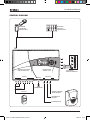
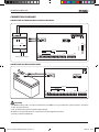
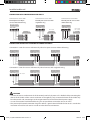
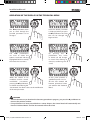
EXAMPLE OF CONNECTION OF A SIREN TO THE CONTROL PANEL
– 12Vcc MCA PCS
MANS
Siren
terminaldella
block
Morsettiera
Sirena
BRAHMS SA10L
M1
BUS
F2
CN4
C4UC0801
CN3
C4UC0401
C4UC0201
OFF
24h
24h
+
–
+ MCS PCS
Z1
C
M3
M2
Z2
Z3
C
Z4
+
–
Z5
C
Z6
Z7
C
Z8
NC NA
C MCA PCA
GND
OUT4
OUT3
OUT2
OUT1
+
AUX OUTPUTS
F1
–BAT
–
GND
RXD
TXD
+5V
BXRS23
+BAT
CN2
–
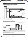
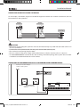
CONNECTION OF THE (OPTIONAL) BOARD C4MO0401
+
Power
supply source
Sorgente
di alimentazione
NA
M1
BUS
–
C
NC
+ MCS PCS
NA
C
NC
NA
F2
M2
Z4
+
–
Z5
C
M3
GND
OUT4
OUT3
OUT2
OUT1
+
AUX OUTPUTS
CN3
NC
GND
RXD
TXD
+5V
BXRS23
C4UC0801
C
C
CN4
NA
C
NC
CN2
Z7 Cimage
Z8
NCillustrates
NA C MCA PCA an
–
This
example of a possible connection of the loads to the 4 relay outputs of the output
module in NO mode; it is of course also possible to choose the NC connection mode.
The capacity of the relay contacts is 1 A, 12 – 24 V DC.
Z6
13
C4UC_Inst_EXPO 24800300 08-02-10.indd 13
08/02/10 10:49