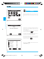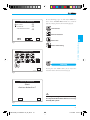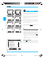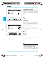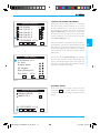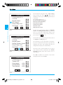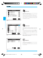
1
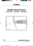
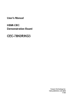
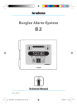
Burglar Alarm System B2 1 2 3 4 5 6 7 8 9 10 12:30 Fri 03rd March Partial Armed Disarmed Installation instructions 10_08 / 24848501 B2UC0002_Inst 24848501 10_08_GB.1 1 7-10-2008 10:53:02 2 B2UC0002_Inst 24848501 10_08_GB.2 2 7-10-2008 10:53:05 CONTENTS Safety notes .................................................................................. 4 1- GENERAL SYSTEM INFORMATION Page 5 General Diagram ....................................................................... 6 Devices that can be connected to the Control Panel................................................................ 7 Absorption of the system components ............................................................... 7 Technical characteristics of the Control Panel B2UC0002...................................... 8 2- CONNECTION DIAGRAMS Page 9 Connection of the devices to the system bus ................................................................... 10 Connection of the Power Supplier B2AL0001 ................................ 11 Connection of the GSM module or generic loads to the Power Supplier ........................ 12 Connection of the sensors to the modules B2MIA101 ............................................... 13 Connection of the sensors to the modules B2MI0401 ................................................ 14 Connection of loads to the module B2MO0201................................................ 16 Connection to YDRA supervision systems ........... 17 Connection to BPT MITHO terminals ....................... 18 Anti-tampering cover EBTAM ........................................ 19 Connection of the metal container B2CTME01............................................. 20 Connection of the plastic container B2CTPL01 ............................................ 20 Installation of the Control Panel B2UC0002 ................................................... 21 3- COMMISSIONING Page 23 Introduction ............................................................................... 24 Commissioning of the system....................................... 25 Learning ........................................................................................ 26 Identification.............................................................................. 28 - Device identification ....................................................... 28 - Assigning a symbolic name to the devices ...................................................................... 29 - Check module operation ............................................. 30 - State of the connected sensors ............................... 31 - Erasing a device ................................................................. 31 Device Test................................................................................... 33 - Input Test ................................................................................ 34 - Output Test............................................................................ 34 - Siren Test ................................................................................. 34 - Battery Test ............................................................................ 35 - Transmission Quality Test ............................................. 35 Date & Time Setting .............................................................. 36 Commissioning complete ............................................... 37 3 B2UC0002_Inst 24848501 10_08_GB.3 3 7-10-2008 10:53:05 Safety notes WARNING • • • • • • • • • • • • Carefully read the instructions before starting installation. Perform work as specified by the manufacturer. It is prohibited to use the product for purposes other than those specified or which are improper. It is prohibited to tamper with or modify the product. The removal of the labels on the card will void the guarantee. Use original spare parts. Installation, setting, commissioning and maintenance of the product must only be performed by qualified technicians who have been properly trained in compliance with current standards. Installation of security systems is regulated and may be performed by persons who possess the legally required qualifications, including compliance with accident prevention. Operate in sufficiently lighted areas that are conducive to health and use tools, utensils and equipment that are in good working order. Upon completion of installation, always check for correct operation of the unit and the system as a whole. Do not install the devices outdoors or in areas where they are exposed to seepage or splashes of water. Handle the devices with care. They contain electronic parts that are fragile and sensitive to humidity. Always disconnect the power supply before doing any work on the devices. The electrical system must comply with current standards in the country of installation. 4 B2UC0002_Inst 24848501 10_08_GB.4 4 7-10-2008 10:53:05 GENERAL SYSTEM INFORMATION General system information 1 5 B2UC0002_Inst 24848501 10_08_GB.5 5 7-10-2008 10:53:05 General Diagram General system information 1 Infrared sensor B2IPPA01 Control Panel B2UC0002 2 Relay output module B2MO0201 B Keypad BXTAIN01 C D Power supplier B2AL0001 A External siren B2SEAL02 4-Input module B2MI0401 Infrared key receiver BXINIR Powered input module B2MIA101 Powered generic sensor Infrared key BXKEIR01 The system bus allows: • non-polarized connection of the devices; • maximum wiring length of 800 metres (A+B+C+D in the figure) and a maximum distance of 400 metres between the power supplier and the most distant device (B+D in the figure) (*); • maximum current available for devices on bus 1 A (*). • connection of a maximum of 32 devices which are part of the system with free typology. (*)These distances can be achieved by adding the repeater modules B2RP0001 and B2RPAL01 not shown in the drawing. If these devices are not present, the distance and current values shown are halved. WARNING In order to obtain the best system performance, it is recommended that you use unshielded, non-polarized twisted pair with a minimum section of 0.5 mm2. 6 B2UC0002_Inst 24848501 10_08_GB.6 6 7-10-2008 10:53:05 Devices that can be connected to the Control Panel Description Recessed keypad Passive infrared sensor 2 Relay output module Powered 1 input module Non-powered 4 input module Self-powered external siren Power supplier Code BXINIR BXKEIR01 BXGM0001 BRP0001 BRPAL01 B2DTPA01 BXRS4201 Description IR key receiver that can be used only with the key BXKEIR01 Infrared key GSM communicator BUS signal repeater module Power supply repeater module Volumetric detector Interface module The BXIRI receiver can be integrated in the standard bodies listed in the table below. Code BXINIRMA BXINIRLV BXINIRLI BXINIRTL BXINIRPB Model Ticino Magic Ticino Living Ticino Living International Ticino Living Light Gewiss Play Bus Code BXINIRGB BXINIRVN BXINIRVB BXINIRAN BXINIRAB Model Gewiss 20 Vimar Idea black Vimar Idea white Ave Noir Ave Blanque 1 General system information Code BXTAIN01 B2IPPA01 B2MO0201 B2MIA101 B2MI0401 B2SEAL02 B2AL0001 Absorption of the system components DEVICES Control Panel B2UC0002 Recessed keypad BXTAIN01 Passive infrared sensor B2IPPA01 2 Relay output module B2MO0201 Powered 1 input module B2MIA101 Non-powered 4 input module B2MI0401 Self-powered external siren B2SEAL02 Infrared key receiver BXINIR GSM communicator BXGM0001 Volumetric detector B2DTPA01 Interface module BXRS4201 AVERAGE ABSORPTION 25 mA 22 mA 9 mA 12 mA (without output load) 13 mA 3 mA 18÷100 mA 30 mA 110 mA 16 mA 50 mA WARNING The sum of the current absorbed by the devices connected to the bus must not exceed the maximum current available from the power supplier (500 mA). 7 B2UC0002_Inst 24848501 10_08_GB.7 7 7-10-2008 10:53:06 Technical characteristics of the Control Panel B2UC0002 General system information 1 Main power supply • Power supply voltage • Max current absorbed The module can ONLY be powered by means of the system BUS 12÷35 V DC 30 mA Mechanical characteristics • Weight • Dimensions (L x H x D) • Container material • Protection rating Security Level II as per CEI 79-2 170 g 116x95x27 mm ABS IP30 Climatic characteristics • Operating temperature • Maximum relative humidity during operation • Storage temperature • Maximum relative humidity for storage 0 ÷ 40 °C 93% RH without condensation -10 ÷ +50 °C 85% RH with no condensation The touchscreen keypad as well as the supplementary keypad BXTAIN01 provides each user with more than 1,000,000 combinations for the access code. 8 B2UC0002_Inst 24848501 10_08_GB.8 8 7-10-2008 10:53:06 CONNECTION DIAGRAMS Connection diagrams 2 9 B2UC0002_Inst 24848501 10_08_GB.9 9 7-10-2008 10:53:07 Connection of the devices to the system BUS An example of the connection of the keypad (BXTAIN01), expansion modules (B2MO0201, B2MI0401, B2MIA101), siren (B2SEAL02), IR key receiver (BXINIR), sensor (B2IPPA01) and Control Panel (B2UC0002) on the B2 BUS. BUS + – I1 T1 I3 T3 –3 I4 T4 –4 I1 T1 –1 I2 T2 –2 BUS BUS B2MIA101 B2MI0401 B2MO0201 BUS + 12 V – BXTAIN01 NC1 C1 NA1 NC2 C2 NA2 Connection diagrams 2 B2AL0001 M2 24 V 30 V M1 BUS + 12 V – + – BAT TAMPER M3 BUS B2DTPA01 BUS B2SEAL02 BUS BXINIR BUS B2IPPA01 BUS NO1 C1 NC1 NO2 C2 NC2 NO3 C3 NC3 NO4 C4 NC4 B2UC0002 10 B2UC0002_Inst 24848501 10_08_GB.10 10 7-10-2008 10:53:07 Connection of the Power Supplier B2AL0001 230 V L N B2AL0001 M2 T 24 V 30 V M1 BUS WARNING + 12 V – + – BAT TAMPER M3 NO1 C1 NC1 NO2 C2 NC2 NO3 C3 NC3 NO4 C4 NC4 BB065 12 Vcc 7Ah – + BB065 12 Vcc 7Ah – + • The unit is powered at mains voltage, 230 V AC - 50/60 Hz. Therefore, it must be provided with an earth connection using the appropriate terminals. Failure to connect all accessible metal parts to the earth will make the unit unsafe to use. • For the 230 V AC power supply, it is essential to use a cable with double insulation (with double sheath), as set forth in electrical safety standards. • Use wire terminals for connection to the mains at 230V AC - 50/60 Hz. • Protect the appliance using a suitable disconnection device to protect the power supply network such as an easily accessible bi-polar switch (or other). • Use a cable passage hole only for the passage of the cable for connection to the 230V AC - 50/60 Hz mains. • The backup battery should only be replaced by qualified personnel. Dispose of the unit in accordance with current standards. Use only sealed lead batteries. Connection diagrams 2 11 B2UC0002_Inst 24848501 10_08_GB.11 11 7-10-2008 10:53:07 Connection of the GSM module or generic loads to the Power Supplier B2AL0001 M2 BXGM0001 2 24 V 30 V M1 Connection diagrams BUS LA M1 BUS BUS B2 + 12 V – + – BAT M2 TAMPER M3 NO1 C1 NC1 NO2 C2 NC2 NO3 C3 NC3 NO4 C4 NC4 B2AL0001 M2 24 V 30 V U1 M1 BUS + 12 V – + – BAT TAMPER U2 M3 U3 NA1 C1 NC1 NA2 C2 NC2 NA3 C3 NC3 NA4 C4 NC4 U4 Max 24Vcc 12 B2UC0002_Inst 24848501 10_08_GB.12 12 7-10-2008 10:53:07 Connection of the sensors to the modules B2MIA101 Connection for sensors with Normally Open or Normally Closed contacts without balancing. Connection for sensors with Normally Closed contacts with Two Resistance Mode. TAMPER ALLARME + – RFL=2.2K RA=2.2K Connection diagrams 2 TAMPER ALLARME + – B2MIA101 B2MIA101 BUS + – I1 –1 BUS + – I1 –1 Connection for sensors with Normally Closed contacts with One Resistance Mode. RFL= 2.2 K TAMPER ALLARME + – B2MIA101 BUS + – I1 –1 13 B2UC0002_Inst 24848501 10_08_GB.13 13 7-10-2008 10:53:08 Connection of the sensors to the modules B2MI0401 Connection of 4-wire magnetic contacts and wall/ fence-breaking sensors (RIN01). 2 Connection diagrams CIO21-CIO23-CIP31-CPA31CSA31-CSP21-RIN01 Connection of magnetic contacts and wall/fencebreaking sensors (RIN02) with four terminals. CSA11-CSA12-RIN02RVB02 ALLARME TAMPER B2MI0401 B2MI0401 BUS I1 T1 –1 I2 T2 BUS I1 T1 –1 I2 T2 Connection of 2-wire cable contacts for shutters. CFSST Connection of magnetic contacts with two terminals. CSP01-CSP02 ALLARME B2MI0401 B2MI0401 BUS I1 T1 –1 I2 T2 BUS I1 T1 –1 I2 T2 14 B2UC0002_Inst 24848501 10_08_GB.14 14 7-10-2008 10:53:08 Connection of the sensors to the modules B2MI0401 Connection of magnetic contacts with two wires. 2 Connection diagrams CXP31-CIO22 B2MI0401 BUS I1 T1 –1 I2 T2 BRAHMS CONTACTS AND SENSORS CONTACTS FOR SHUTTERS AND BLINDS CFSST cable contact pre-wired two wires MAGNETIC CONTACTS CIO21 magnetic recessed with four wires CIO22 magnetic recessed with two wires CIO23 magnetic recessed with four wires CIP31 magnetic recessed with four wires CIPA31 magnetic contact for garage door with four wires CSA11 surface mounted magnetic contact with four terminals CSA12 surface mounted magnetic contact with four terminals CSA31 surface mounted magnetic contact with four wires CSP01 surface mounted magnetic contact with two terminals CSP02 surface mounted magnetic contact with two terminals CSP21 surface mounted magnetic contact with four wires CXP31 surface mounted magnetic contact with two wires VIBRATION SENSORS RIN01 wall/fence breaking sensor with 4 wires RIN02 wall/fence breaking sensor in box with four terminals RVB02 glass-breaking sensors with 6 terminals 15 B2UC0002_Inst 24848501 10_08_GB.15 15 7-10-2008 10:53:08 Connection of loads to the module B2MO0201 Connection of the 2-Relay output module B2MO0201 to a generic load (U1 and U2). B2MO0201 Connection diagrams 22 2 NC1 C1 NA1 NC2 C2 NA2 1 BUS Max 24Vcc U1 U2 16 B2UC0002_Inst 24848501 10_08_GB.16 16 7-10-2008 10:53:09 Connection to YDRA supervision systems YDIETH00 M2 – + RJ45 ETHERNET Connection diagrams 22 – TX– TX+ RX– RX+ SWITCH ETHERNET 1 2 BXRS4201 PC YDRA RX+ RX– TX+ TX– – S ® CN1 B2UC0001 CN2 BUS B2AL0001 M2 24 V 30 V M1 BUS + 12 V – + BAT – TAMPER 230Vac 17 B2UC0002_Inst 24848501 10_08_GB.17 17 7-10-2008 10:53:09 Connection to BPT Mitho terminals VAS/100MH MITHO AL M1 SEC – + + 18V – 230V B 22 M2 – + 18V Connection diagrams SW4 230V 50Hz 18V 10VA 230V PRI MM B2UC0002 BUS B2 BUS CN2 BXRS4201 CN1 RX+ RX– TX+ TX– – S OH/GW M2 R+ R– T+ T– – M4 MM M3 M1 CN1 LA 12÷24 V DC 230V 18 B2UC0002_Inst 24848501 10_08_GB.18 18 7-10-2008 10:53:09 Anti-tampering cover EBTAM The use of this cover (fig. 2) is indispensable if the modules are to be equipped with an anti-opening and antitampering device in order to achieve the Security Level II as per the Standard CEI 79-2. B A 22 Connection diagrams INSTALLATION The modules (B2MIA101, B2MI0401, B2MO0201) can be wall-mounted on a completely flat surface or mounted inside a junction box or even on a DIN rail (fig. 1). Remove the jumper present on the module and insert the one present on the cover (fig. 3). Fix the protection to the module with the screws provided (fig. 4), being very careful that, in the chosen position, the lever (A) of the protection’s microswitch is operated and the connection cable (B) between the cover and the module is not accidentally positioned between the two elements. 2 1 3 2 1 4 19 B2UC0002_Inst 24848501 10_08_GB.19 19 7-10-2008 10:53:11 Connection of the B2CTME01 metal container ER + TBA - + 12V P TAM V~ 24 Connection diagrams 2 Connection of the B2CTPL01 plastic container ER AT + P TAM B - + 12V ~ 24V 20 B2UC0002_Inst 24848501 10_08_GB.20 20 7-10-2008 10:53:12 Installation of the Control Panel B2UC0002 Connection diagrams 2 2 1 5 7 6 Open the unit by using a screwdriver in the slot (fig. 5). Fasten the base to the wall using the screws and plugs provided or on a recessed box (fig. 6). We recommend you install it on a flat surface, being careful not to over tighten screws. Connect the wires of the twisted pair to the terminals of the provided connector and insert it on the printed circuit (fig. 7). Close the unit. After connecting the various system devices, connect the power supplier B2AL0001 to the local network. 21 B2UC0002_Inst 24848501 10_08_GB.21 21 7-10-2008 10:53:12 RX+ RX– TX+ TX– – S BXRS4201 Interfaccia RS 422 CN1 ☝ Connection diagrams 2 O N1 2 CN1 3 4 8 9 An additional terminal in SLAVE configuration can also be installed in a system. From a SLAVE-configured terminal, it is possible to totally or partially arm/disarm the system. No other terminal function can be accessed. In order to operate in SLAVE mode, the terminal must be configured as indicated in figure 8. If you want to connect a Brahms B2 burglar alarm system to a Mitho BPT terminal or a YDRA supervision system, the BXRS4201 module (fig. 9) must be installed using the CN1 connector provided (fig. 8). 22 B2UC0002_Inst 24848501 10_08_GB.22 22 7-10-2008 10:53:12 COMMISSIONING Commissioning 3 23 B2UC0002_Inst 24848501 10_08_GB.23 23 7-10-2008 10:53:12 Introduction System language Commissioning 3 The objectives of the “Commissioning” are the following: - Setting the language of the system. - Check that all the connections have be made correctly. - Check that the Control Panel is able to communicate with all the system devices. - Check the correct operation of each device. - Set the main parameters of each device. Thus this chapter will only illustrate the functions regarding Commissioning; all other functions have been intentionally omitted here and will be covered in the Installer Manual. Detection of all the System devices Not all the devices have been detected Learn Make any changes necessary R All the devices have been detected We recommend that you follow the procedure illustrated to the side that summarizes the essential steps for a correct “Commissioning”. I I I I I I I Identify Identify the devices making up the system by assigning them names reflecting their location or use. Inputs State No device in alarm TEST Device in alarm Check connections and type of balancing Test Input Test Output Test Alarm Test Battery Test Date and Time Setting 1 2 END 24 B2UC0002_Inst 24848501 10_08_GB.24 24 7-10-2008 10:53:13 Commissioning of the system When the system is started for the first time, after a brief standby period (fig. 1), by pressing the appropriate icon it will be possible to choose the system language. Choose Language ESP ENG FRA ITA The “Choose Language” window will appear automatically when the system is turned on or turned back on after a complete power outage. POR ESC Fig. 1 1 2 3 4 5 6 7 8 9 10 12:30 Fri 03rd March Armed Partial Once you have chosen the system language, provide for automatic detection of the connected devices. (fig. 2). Push the icon A keypad will appear on which to enter the Installer Code (which at the first start-up will be 5, 6, 7, 8, fig. 3) in order to access the Installer Menu (fig. 4). 3 Commissioning DEU Disarmed Fig. 2 Enter Code 1 2 3 4 5 6 7 8 Esc 9 0 OK Fig. 3 25 B2UC0002_Inst 24848501 10_08_GB.25 25 7-10-2008 10:53:13 Installer Menu S S S I I I S I S S S I I I Learn View Identify P P P 1 2 3 4 5 6 7 8 9 0 TEST When the appropriate icon is pressed, the system automatically detects the connected devices (fig. 4). ESC 3 Commissioning Learning Setting MEM ORY 1 2 Learn P P P P Fig. 4 Devices Detected Start devices detection? OK At this point, a list will appear with the number of devices detected and a different icon for each type of device (figg. 6, 7). To scroll through the complete list of detected devices, press the buttons . ESC If a device is not recognized during this phase, it may not have been connected correctly. Fig. 5 Once the connection problems have been resolved, the detection of the devices can be repeated by simply pressing the icon R . Devices Detected A POWER SUPPLIER UC CONTROL PANEL In 4 IN MODULE In 1 IN PW MODULE 12V Out 2 OUT MODULE IR WALL IR SENSOR 01 01 01 01 02 03 R Pressing the icon ESC, we will now return to the “Installer Menu” (fig. 8). ESC Fig. 6 26 B2UC0002_Inst 24848501 10_08_GB.26 26 7-10-2008 10:53:13 On the following pages we will analyze ONLY the items of the “Installer Menu” which are useful for properly carrying out the commissioning (fig. 8). Devices Detected 01 03 03 EXT. SIREN IR RECEIVER SUPPLEMENTARY KEYPAD Learn Learn devices I I I I I I I Identify Devices Detection ESC R TEST Device Test 3 1 2 Commissioning Fig. 7 Date & Time Setting Installer Menu S S S I I I S I I I I Learn Identify P P P P S S S View P P P Setting MEM ORY 1 2 TEST 1 2 3 4 5 6 7 8 9 0 Learn ESC Learning Pressing the icon “Learn” allows you to repeat the detection of the connected devices (fig. 9). Fig. 8 Devices Detected Start devices detection? OK ESC Before proceeding with the commissioning, it is important that all the devices are recognized by the system Fig. 9 27 B2UC0002_Inst 24848501 10_08_GB.27 27 7-10-2008 10:53:14 Devices Detection In In In In In ID: 022228237 V:0.1 DEL Power Supplier A PW. OUT 01.1 A PW. OUT 01.2 A PW. OUT 01.3 A PW. OUT 01.4 ID: 02228296 V:0.1 A ESC OK DEL Devices Detection Commissioning 3 01 OUT Module OUT Module 01.1 Out 2 OUT Module 01.2 ID: 022228259 V:0.1 DEL Devices Detection In 12V 12V 1 IN PW Mod 01.1 IR Sensore IR Par. IR Wall IR 01.1 ESC OK DEL Devices Detection ESC OK 01 Rec. Keypad REC Keypad 01.1 ID: 022228226 V:0.1 ID: 022228333 V:0.1 ESC OK DEL ESC OK Fig. 10 Devices Detection In In In In In 4 4 4 4 4 IN IN IN IN IN I I I Identification By pressing the appropriate icon, we will now proceed with the identification of the devices. During this phase of the commissioning, we can identify, name and program the components of the burglar alarm system. To facilitate the identification of each individual device and its outputs or inputs, numbered progressively, these will now appear in a list divided over several pages (fig. 10). To scroll through the pages containing the list of . devices, use the icons Devices Detection 01 EXT Siren 01.1 DEL 01 ID: 022228632 V:0.1 ID: 022228382 V:0.1 Ext. Siren ESC OK Devices Detection 01 1 IN PW Module In DEL ESC OK Out 2 ESC OK I Identify Out 2 ID: 022228233 V:0.1 DEL 01 Devices Detection 01 IR Receiver IR Receiver 01.1 I I I Devices Detection 01 4 IN Module Mod 4 IN 01.1 Mod 4 IN 01.2 Mod 4 IN 01.3 Mod 4 IN 01.4 Module Mod 01.1 Mod 01.2 Mod 01.3 Mod 01.4 01 In the event, once the siren has been recognized, it is necessary to perform work on the installation and on the wiring of the siren itself, (or branches upstream from the siren), it is necessary to proceed as follows in order to avoid the ’“Tamper Alarm”: 1- Erase the Siren(s) by pressing on the button DEL . 2- Carry out the necessary operations on the installation. 3- Perform the detection of the Siren(s) again and recheck the setting. DEVICE IDENTIFICATION allows you to activate the LEDs and The icon buzzers present on the connected devices and identify their position within the environment (fig. 11). ID: 022228776 V:0.1 DEL OK ESC Fig.11 28 B2UC0002_Inst 24848501 10_08_GB.28 28 7-10-2008 10:53:14 Consider a 4-input module as an example; the first line (fig. 12) cannot be changed, it contains the default name assigned by the system and represents the type of device recognized. Devices Detection In In In In In 01 4 IN Module Mod 4 IN 01.1 Mod 4 IN 01.2 Mod 4 IN 01.3 Mod 4 IN 01.4 ID: 022228237 V:0.1 DEL ESC OK 3 Devices Detection In In In In In 01 4 IN Module Mod 4 IN 01.1 Mod 4 IN 01.2 Mod 4 IN 01.3 Mod 4 IN 01.4 ID: 022228237 V:0.1 DEL ESC OK ASSIGNING A SYMBOLIC NAME TO THE DEVICES The next lines on the page (fig. 13) represent each of the 4 inputs to which an external sensor can be connected; pressing on the text, an alphanumeric keypad will appear which allows us to assign them a name. We recommend that you use a symbolic name that identifies their position, for example garage 01.1, or that identifies their use, for example Gas detector (fig. 14). Press OK to confirm the selections made before exiting from the screen with ESC. Commissioning Fig.12 Fig.13 Once these operations have been carried out for all the connected devices, whether these are entry panels, outputs, sirens, IR receivers or what have you, we will have a precise picture of the location of each component and/or its function. Enter Zone Name Garage 01.1 A B C D E F G H I J K L M N O P Q R S T U V W X Y Z ' . - 0 1 4 5 6 7 8 CAP 2 OK 3 DEL BkSp 9 ESC It is advisable that you carry out the identification operations carefully, as the names assigned to the devices during this phase will help you to recognize them during the setting phase as well. Fig.14 29 B2UC0002_Inst 24848501 10_08_GB.29 29 7-10-2008 10:53:15 Devices Detection IR Sensore IR Par. IR Wall IR 01.1 01 CHECK MODULE OPERATION We will now consider as an example another device recognized by the system during detection, and we will analyze the column indicated by the arrow (fig. 15). Clicking on this icon, we act on the state of the device as follows: On ID: 022228632 V:0.1 DEL Commissioning 3 OK Off ESC In Test state Fig. 15 With the device in test state we can perform maintenance on the installation while keeping it active but avoiding the effective sounding of the alarm sirens; the activation of the devices, however, will be indicated in the “Event Log”. Devices Detection IR Sensore IR Par. IR Wall IR 01.1 01 The second column (fig. 16) cannot be changed from the display, as it shows the effective state of the connected device: Alarm ID: 022228823 V:0.1 DEL OK Tamper ESC Fault Fig. 16 Press OK to confirm the selections made before exiting from the screen with ESC. - The state of the devices set during this phase (On, Off, in Test State) become a permanent state which cannot be modified by the User. - In order to avoid false alarms or malfunctioning, it is recommended to turn Off all the unconnected inputs. 30 B2UC0002_Inst 24848501 10_08_GB.30 30 7-10-2008 10:53:15 Devices Detection In In In In In 4 IN Module Mod 4 IN 01.1 Mod 4 IN 01.2 Mod 4 IN 01.3 Mod 4 IN 01.4 01 STATE OF THE CONNECTED SENSORS During this commissioning phase, it is important that none of the connected inputs are in a state of alarm; otherwise, it is necessary to check that the connection is correct and consistent with the “Type of Balancing” parameter for each input; in order to do this, just press on the icon of the device in alarm (fig. 17) in order to access the window “Input Setting” (fig. 18). ID: 022228456 V:0.1 OK ESC Fig. 17 Input Setting The first line of the “Input Setting” page contains the name that we have assigned to the input during the identification phase (this name, however, can also be changed from this window using the procedures described previously). 4 IN Module 01.4 01 Area Burglar Alarm NC contact Entry Delay=000 Exit Delay =000 OK From this window it is possible to access all the setting functions, but for the commissioning we will limit ourselves only to the parameters necessary for correct recognition of the inputs by the control panel, referring to the setting manual for further information. 3 Commissioning DEL ESC Fig. 18 Devices Detection IR Sensore IR Par. IR Wall IR 01.1 01 ERASING A DEVICE In the event you must remove a device, just press the button DEL (fig. 19) and confirm the selection so that the device is no longer recognized by the system. ID: 022228632 V:0.1 DEL OK ESC Fig. 19 31 B2UC0002_Inst 24848501 10_08_GB.31 31 7-10-2008 10:53:16 Input Setting 4 IN Module 01.4 01 Area Burglar Alarm NC contact Entry Delay=000 Exit Delay =000 Commissioning ESC OK 3 On the fourth line (fig. 20), of the “Input Setting” allows you to page, pressing the icons identify the correct type of balancing for the input in question. The available options are: NC contact (Normally Closed) NO contact (Normally Open) One Resistance Mode Two Resistance Mode Vibration Sensor Rolling Shutter Sensor For the types of balancing defined as “Vibration Sensor” and “Rolling Shutter Sensor”, you will also have to set the pulse length, pulse number and time interval (fig. 22); to access these parameters, press on the icon (fig. 21). Fig. 20 Input Setting For the other types of balancing, we will be able to set “Tamper” and “Gong” (fig. 22). 4 IN Module 01.4 01 Area Burglar Alarm Rolling Shutter Sensor Entry Delay=000 Exit Delay =000 The correctness of the connections and balancing can be checked from the inputs, by purposely triggering the alarms and checking that they are recognized correctly by the Control Panel. ESC OK Fig. 21 This phase of the commissioning can be considered completed when, returning to the “Devices Detection” window, none of the devices are in a state of alarm. Press OK to confirm the selections made before exiting from the screen with ESC. Input Setting 4 IN Module 01.4 Tamper OFF Pulse Lenght Pulse Number Time Interval =000 =000 =000 OK ESC Fig. 22 32 B2UC0002_Inst 24848501 10_08_GB.32 32 7-10-2008 10:53:16 Installer Menu S S S I I I S I I I I Learn Identify S S S View Device Test P P P Setting MEM ORY 1 2 TEST P P P P TEST 1 2 3 4 5 6 7 8 9 0 From the “Installer Menu” (fig. 23), pressing the icon “Test” will take us to the “Test Menu” (fig. 24) that allows us to test the correct operation of the connected devices. Each individual test available is analyzed below. ESC 3 Commissioning Fig. 23 Test Menu In In Out Out In In 12V Out Out 12V ESC Fig. 24 33 B2UC0002_Inst 24848501 10_08_GB.33 33 7-10-2008 10:53:17 In In Input Test In 4 IN MOD 01.1 In 4 IN MOD 01.2 In 4 IN MOD 01.4 WALL IR SENSOR 01 IR IR 12V In In 12V WALL IR SENSOR 02 ESC INPUT TEST Only the inputs that are in a state of alarm will appear in this window (fig. 25). Thus, by materially activating the inputs, we can check their correct operation, name and location. If the balancing of the inputs has been set correctly and the inputs are not effectively activated, this window must be empty. Commissioning 3 Fig. 25 Out Out Input Test PW. A PW. A PW. A PW. Out MOD. 2OUT Out MOD. 2OUT A 01/1 01/2 01/3 01/4 01/1 01/2 Out Out On Off On Off On Off ESC Fig. 26 OUTPUT TEST All the connected outputs will appear in this window, with the icon in the right column (fig. 26) on Off. By pressing the pen provided on the icon Off, the state of the output will change to On and the output will be activated in order to allow us to check its operation. When exiting from the window by pressing the icon ESC, any outputs that may have been left active will automatically be deactivated. Siren Test EXT. SIREN 01 EXT. SIREN 02 On Off SIREN TEST The legend “On” or “Off” next to the name of the device acts as a switch (fig. 27). By simply pressing on the legend we can turn the sirens on or off. ESC Fig. 27 34 B2UC0002_Inst 24848501 10_08_GB.34 34 7-10-2008 10:53:17 Battery Test A BATTERY TEST PW. 01 EXT. SIREN 02 By simply pressing on the name of the device, we will be informed about the state of the battery housed inside the device (figg. 28, 29). ESC 3 Commissioning Fig. 28 Battery Test Battery CHARGED ESC Fig. 29 Transmission Speed IR IR IR IR Bedroom Sensor Bathroom Sensor Kitchen Sensor Garage Sensor OK 9 8 9 8 ESC TRANSMISSION QUALITY TEST Pressing the appropriate icon, a list of the inputs will appear with a numerical value next to each that indicates the speed and quality of communication between the Control Panel and the device, on a scale from 1 to 10 (fig. 30). If the value is less than 7, check that the length of the connection is within the limits indicated in the section “General system information”. Fig. 30 35 B2UC0002_Inst 24848501 10_08_GB.35 35 7-10-2008 10:53:17 Date & Time Setting Hours 55 ESC OK 3 Commissioning 18 1 2 Fig. 31 Date & Time Setting From the “Installer Menu”, pressing the appropriate icon will take us to the window for the Date and Time Setting. Set the correct time by selecting the area to be modified (fig. 31) and using the arrows on the side. Proceed in the same manner to set the date after having pressed the arrow at the bottom of the window (fig. 32) which allows access to the appropriate screen (fig. 33). Press OK to confirm the selections made before exiting from the screen with ESC. Date & Time Setting Hours 19 58 ESC OK Fig. 32 Date & Time Setting Date Gio 17 Month-Year Gen 08 OK ESC Fig. 33 36 B2UC0002_Inst 24848501 10_08_GB.36 36 7-10-2008 10:53:18 Commissioning complete At this point the commissioning can be considered as completed, and the system is ready to operate. It is possible to arm the system, trigger the alarms and check that all the devices respond correctly. For the system activation and deactivation procedures, refer to the “User Manual”. Commissioning 3 37 B2UC0002_Inst 24848501 10_08_GB.37 37 7-10-2008 10:53:18 3 38 B2UC0002_Inst 24848501 10_08_GB.38 38 7-10-2008 10:53:18 3 39 B2UC0002_Inst 24848501 10_08_GB.39 39 7-10-2008 10:53:19 BRAHMS ELETTRONICA S.r.l. Via Gran Sasso, 18 20010 Bareggio/MILANO/Italy http: www.brahmselettronica.it e-mail: [email protected] 40 B2UC0002_Inst 24848501 10_08_GB.40 40 7-10-2008 10:53:19