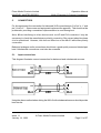
1
MASELEC MASTER SERIES
MLA-2 Precision 2-Channel
Compressor
Operation Manual
Issue 1.1 January 14, 1998
Prism Media Products Limited
MASELEC MASTER SERIES
Operation Manual
MLA-2 Precision 2-Channel Compressor
CONTENTS
1.
INTRODUCTION . . . . . . . . . . . . . . . . . . . . . . . . . . . . . . . . . . . . . . . . . . . . . . 4
2.
SUMMARY OF MLA-2 FEATURES . . . . . . . . . . . . . . . . . . . . . . . . . . . . . . . . 4
3.
GETTING STARTED . . . . . . . . . . . . . . . . . . . . . . . . . . . . . . . . . . . . . . . . . . . 5
3.1. Unpacking your MLA-2 . . . . . . . . . . . . . . . . . . . . . . . . . . . . . . . . . . . . 5
3.2. Using the MLA-2 for the first time . . . . . . . . . . . . . . . . . . . . . . . . . . . . 5
3.3. MLA-2 product concept and capabilities . . . . . . . . . . . . . . . . . . . . . . . 6
3.4. Example : MLA-2 in a mastering chain . . . . . . . . . . . . . . . . . . . . . . . . 9
3.5. Example : MLA-2 on a mixer stereo output . . . . . . . . . . . . . . . . . . . 10
4.
OPERATION . . . . . . . . . . . . . . . . . . . . . . . . . . . . . . . . . . . . . . . . . . . . . . . .
4.1. Input gain . . . . . . . . . . . . . . . . . . . . . . . . . . . . . . . . . . . . . . . . . . . . .
4.2. Output gain . . . . . . . . . . . . . . . . . . . . . . . . . . . . . . . . . . . . . . . . . . . .
4.3. Ratio . . . . . . . . . . . . . . . . . . . . . . . . . . . . . . . . . . . . . . . . . . . . . . . . .
4.4. Attack time . . . . . . . . . . . . . . . . . . . . . . . . . . . . . . . . . . . . . . . . . . . .
4.5. Release time . . . . . . . . . . . . . . . . . . . . . . . . . . . . . . . . . . . . . . . . . . .
4.6. VU/GR . . . . . . . . . . . . . . . . . . . . . . . . . . . . . . . . . . . . . . . . . . . . . . . .
4.7. Compressor in/out . . . . . . . . . . . . . . . . . . . . . . . . . . . . . . . . . . . . . . .
4.8. Compressor indicator lamp . . . . . . . . . . . . . . . . . . . . . . . . . . . . . . . .
4.9. Stereo linking . . . . . . . . . . . . . . . . . . . . . . . . . . . . . . . . . . . . . . . . . .
4.10. Threshold range . . . . . . . . . . . . . . . . . . . . . . . . . . . . . . . . . . . . . . . .
12
12
13
14
16
17
18
19
19
19
20
5.
CONNECTORS . . . . . . . . . . . . . . . . . . . . . . . . . . . . . . . . . . . . . . . . . . . . . .
5.1. Input connections . . . . . . . . . . . . . . . . . . . . . . . . . . . . . . . . . . . . . . .
5.2. Output connections . . . . . . . . . . . . . . . . . . . . . . . . . . . . . . . . . . . . . .
5.3. Rear panel connectors . . . . . . . . . . . . . . . . . . . . . . . . . . . . . . . . . . .
21
21
22
23
6.
SPECIFICATION . . . . . . . . . . . . . . . . . . . . . . . . . . . . . . . . . . . . . . . . . . . . .
6.1. Analogue inputs . . . . . . . . . . . . . . . . . . . . . . . . . . . . . . . . . . . . . . . .
6.2. Analogue outputs . . . . . . . . . . . . . . . . . . . . . . . . . . . . . . . . . . . . . . .
6.3. Performance specification . . . . . . . . . . . . . . . . . . . . . . . . . . . . . . . . .
6.4. Servicing and repair . . . . . . . . . . . . . . . . . . . . . . . . . . . . . . . . . . . . .
6.5. Mains transformer voltage selection . . . . . . . . . . . . . . . . . . . . . . . . .
23
23
24
25
25
26
Issue 1.1
January 14, 1998
© Prism Media Products Limited
Page 2 of 27
Prism Media Products Limited
MASELEC MASTER SERIES
6.6.
6.7.
6.8.
Operation Manual
MLA-2 Precision 2-Channel Compressor
Fuse . . . . . . . . . . . . . . . . . . . . . . . . . . . . . . . . . . . . . . . . . . . . . . . . . 26
Earthing . . . . . . . . . . . . . . . . . . . . . . . . . . . . . . . . . . . . . . . . . . . . . . . 26
Physical dimensions . . . . . . . . . . . . . . . . . . . . . . . . . . . . . . . . . . . . . 26
7.
ELECTROMAGNETIC COMPATIBILITY . . . . . . . . . . . . . . . . . . . . . . . . . . . 27
8.
REFERENCES . . . . . . . . . . . . . . . . . . . . . . . . . . . . . . . . . . . . . . . . . . . . . . 27
Manual Revision History
Issue 1.1 ; January 14, 1998
Issue 1.0A; 29 October 1997
Issue 1.0 ; 27 October 1997
Product Revision History
October 1997
Issue 1.1
January 14, 1998
This manual is for use with units having serial numbers
beginning with ‘1' thus : MLA2-1-xx-xxxx
© Prism Media Products Limited
Page 3 of 27
Prism Media Products Limited
MASELEC MASTER SERIES
1.
Operation Manual
MLA-2 Precision 2-Channel Compressor
INTRODUCTION
The MLA-2 Precision 2-Channel Compressor is intended for professional audio use in
recording, mixing and mastering applications where high performance is required.
The MLA-2 provides a unique set of tools, carefully crafted to provide a compressor whose
sonic character was the most important design objective.
The unique character of the device is evident in the technical description of the behaviour
of the device.
The MLA-2 employs state-of-the art analogue electronics and provides a perfect solution
to analogue mastering needs, especially used in conjunction with Prism Sound A/D and
D/A converters.
Also available in the MASELEC MASTER SERIES is the MEA-2 equalizer.
2.
SUMMARY OF MLA-2 FEATURES
Operational:
C
Easy to operate with input gain controlling compression depth (drive)
C
Minimal gain adjustment needed when changing ratio
C
Optical gain element for smoothness and freedom from noise
C
Dynamically-controlled attack and release to minimize pumping
C
Precision stepped controls
C
“ImageLink” Intelligent dynamic stereo linking system
C
Output gain make-up
C
Switchable gain reduction or signal level (VU) metering
Technical:
C
Low noise
C
Extended headroom with maximum input amplitude of +28dBu
C
Extended frequency response
C
Low distortion
C
Electronically balanced inputs and outputs
Issue 1.1
January 14, 1998
© Prism Media Products Limited
Page 4 of 27
Prism Media Products Limited
MASELEC MASTER SERIES
3.
Operation Manual
MLA-2 Precision 2-Channel Compressor
GETTING STARTED
It is not necessary to read all the manual before being able to use the MLA-2 Precision 2Channel Compressor. This section contains all the information required for you to get
going straight away.
3.1.
Unpacking your MLA-2
Check that you have the following items and that they are undamaged:
"
MLA-2 Precision 2-Channel Compressor unit
"
MLA-2 Precision 2-Channel Compressor operation manual (this book)
"
IEC320 type mains lead with appropriate plug for your supply
Check that the slide switch mounted on the rear panel is set to the correct mains voltage
range (‘120' setting : 90V-130Vac 50-60Hz; ‘240' setting : 180-260Vac 50-60Hz) and that
the plug fitted to the mains lead is of the correct type. If not, DO NOT CONNECT THE
MAINS SUPPLY, but contact your distributor.
Please keep the packaging for re-use in the event that the unit should be shipped to
another location or in the event that it should ever need to be returned to the manufacturer
for repair or upgrade.
3.2.
Using the MLA-2 for the first time
Refer to section 21 for wiring details of connecting leads. Connect a source of balanced
audio to the input connectors on the MLA-2. Connect the output of the MLA-2 to a
monitoring system or to a tape recorder input. Connect the mains supply to the MLA-2 unit.
There is a main power switch on the rear of the unit and an auxiliary switch on the front
which is more convenient to use if the equipment is rack mounted and the rear panel is
inaccessible.
The indicator lamp integral in the rear-mounted mains switch should illuminate when
switched on. If it fails to light the power may be absent or the unit may be faulty. Check the
mains supply, and try again. If the problem is still evident contact your distributor.
Issue 1.1
January 14, 1998
© Prism Media Products Limited
Page 5 of 27
Prism Media Products Limited
MASELEC MASTER SERIES
Operation Manual
MLA-2 Precision 2-Channel Compressor
Set the rear-panel Threshold switch to ‘Low’ for recording or ‘High’ for mastering or for
working on a stereo mix. Pull the switch lever to overcome the safety lock.
Switch the secondary power switch on the front of the MEA-2 to 'ON'. Set the meter
function switch to ‘G.R.’ (Gain Reduction). Set the Compressor In/Out switch to ‘In’. Either
by momentarily muting or disconnecting the inputs, check that the meter indication is at or
very near to 0dB.
(Note : When the unit is first switched on, this indication may be fractionally below the 0dB reading. This
is normal. After a few minutes during which time the unit will stabilise at its normal operating temperature,
this will settle at 0dB)
Re-connect or unmute the inputs. Switch the monitor selection to monitor the MLA-2
output. A suggested starting point for control settings is :
C
C
C
C
C
Ratio : 2
Attack : 0.100
Release : 0.10
Input Gain -10dB
Output Gain +10dB
The unit is now ready to use.
3.3.
MLA-2 product concept and capabilities
The MLA-2 Precision 2-Channel Compressor is designed to provide very high quality
signal processing for the most demanding professional applications. It has been carefully
developed in conjunction with balance engineers, producers and mastering engineers to
be easy to use, to provide a natural and warm sound and to offer a greater degree of
transparency in the presence of compression. The MLA-2 also offers precision controls
which enable exact re-creation of previously-used configurations.
3.3.1.
Driving the compressor
Early compressors or limiting amplifiers had few controls and were simple to operate.
Many such devices are still popular today, despite (or perhaps even as a result of..) the
limitations of their early technology.
Such devices often employed a ‘drive’ control which provided progressively more
compression (depth) and input gain when rotated.
Issue 1.1
January 14, 1998
© Prism Media Products Limited
Page 6 of 27
Prism Media Products Limited
MASELEC MASTER SERIES
Operation Manual
MLA-2 Precision 2-Channel Compressor
Some later devices split this function into two controls, which would have to be operated
together to achieve the same progressive effect without marked shifts in signal amplitude.
The MLA-2 uses the ‘drive’ principle and the control is called ‘Input Gain’. The compression
threshold is left unchanged while the input gain is adjusted to alter compression depth. This
has the advantage that gain and compression depth are adjusted together and so peak
level will only vary by a small amount, determined by the ‘ratio’ which sets the severity of
compression.
Therefore to increase the depth of compression, or to bring the quieter parts of the mix or
instrument dynamics forward, simply rotate the input gain control clockwise until the
desired effect is obtained.
Another problem with less sophisticated designs is that as the ‘ratio’ is increased the
output level drops dramatically.
The MLA-2 reduces this effect, particularly for moderate amounts of gain reduction, by
making small adjustments to the threshold, depending on the ratio setting. This results in
less variation on output level, for a given input range, as the ratio is varied.
For larger amounts of gain reduction (much more than about 4-6dB), as ‘ratio’ is
increased, it will be necessary to compensate by increasing the ‘output gain’.
In general, for mastering applications use the 'High' threshold setting (switch on the rear
of the MLA-2) and for recording applications (such as for an instrument, in an insert point)
use the 'Low' threshold setting.
Issue 1.1
January 14, 1998
© Prism Media Products Limited
Page 7 of 27
Prism Media Products Limited
MASELEC MASTER SERIES
3.3.2.
Operation Manual
MLA-2 Precision 2-Channel Compressor
Dynamic behaviour
The gain element of the MLA-2 is an optical device and not the more conventional VCA.
This provides a smooth transition between linear and compressed operation with a low
level of noise.
One of the main problems for compressors is recovery after loud transients, often called
‘pumping’. To avoid this the attack and release times of the MLA-2 are dynamically
controlled - i.e. program dependent. In short, the nominal attack and release times set by
the controls are modified according to the program content. This is a key feature of the
MLA-2 and one which enables the device to operate effectively and transparently on the
most difficult signals without introducing the excessive distortion or pumping so noticeable
in less sophisticated designs.
Issue 1.1
January 14, 1998
© Prism Media Products Limited
Page 8 of 27
Prism Media Products Limited
MASELEC MASTER SERIES
3.4.
Operation Manual
MLA-2 Precision 2-Channel Compressor
Example : MLA-2 in a mastering chain
The following are examples of MLA-2 settings for use in a typical mastering chain or in an
insertion point in a mixing console. Best results will be obtained with a gain structure where
0VU corresponds to +4dBu and if the chain includes D/A and A/D converters, with 0dBFS
(digital full scale) corresponding to +18dBu.
MLA-2 Examples, D/A-Eq/Comp-A/D
vs
30 OCT 97 11:00:56
Curve
I/P Gain
O/P Gain
Ratio
Least compression
-20
+20
1.4
-10
+13
1.4
-5
+11
2
-2
+11
3
0
+13
8
to
Greatest compression
Note : Typ. attack time : 0.02 msec/dB; typ. release time : 0.2 sec/dB; Thres = High.
These transfer curves are shown for a range of settings from gentle to severe
compression. Use these as a starting point, if you are unsure of suitable settings. With the
suggested gain structure, the compressor will generally prevent clipping, subject to the
Issue 1.1
January 14, 1998
© Prism Media Products Limited
Page 9 of 27
Prism Media Products Limited
MASELEC MASTER SERIES
Operation Manual
MLA-2 Precision 2-Channel Compressor
attack time setting. If clipping occurs and if it is objectionable or must be avoided for other
reasons, try reducing the attack time. If this does not solve the problem, next try reducing
the input gain. (This will result in the finest possible gain trim, as the output gain change
that results is reduced subject to the ratio setting).
3.5.
Example : MLA-2 on a mixer stereo output
This section provides some sample settings that might be selected when using the MLA-2
to control the output of a mixer when driving into a digital recorder or A/D converter. Best
results will be obtained with a gain structure where 0VU corresponds to +4dBu and 0dBFS
(digital full scale) on the A/D output corresponds to +18dBu.
MLA-2 Examples, desk to A/D MLA-2H
vs
30 OCT 97 11:00:56
Curve
I/P Gain
O/P Gain
Ratio
Least compression
-10
+10
1.7
-6
+9
2
-4
+10
3
-1
+11
5
0
+12
8
to
Greatest Compression
Issue 1.1
January 14, 1998
© Prism Media Products Limited
Page 10 of 27
Prism Media Products Limited
MASELEC MASTER SERIES
Operation Manual
MLA-2 Precision 2-Channel Compressor
Note : Typ. attack time : 0.02 msec/dB; typ. release time : 0.2 sec/dB; Thres = High.
The transfer curves are shown for a range of settings from gentle to severe compression.
Use these as a starting point, if you are unsure of suitable settings. With the suggested
gain structure, the compressor will generally prevent clipping, subject to the attack time
setting. If clipping occurs and if it is objectionable or must be avoided for other reasons,
try reducing the attack time. If this does not solve the problem, next try reducing the input
gain. (This will result in the finest possible gain trim, as the output gain change that results
is reduced subject to the ratio setting).
Comparing these settings with those of section 9, it can be seen that in general more gain
is used in the former case of the (digital) mastering chain. In the latter case, the MLA-2
input, driven by a console stereo output might reach +24dBu or more.
In each case, the MLA-2 input level is represented on the horizontal axis with the
compressed MLA-2 output level on the vertical axis.
For exceptionally hot levels and when using A/D converters set with the gain structure
recommended above (such as Prism Sound AD-124 or AD-2) use the Prism Sound
'Overkiller' passive soft clipper in series with the MLA-2 output.
Issue 1.1
January 14, 1998
© Prism Media Products Limited
Page 11 of 27
Prism Media Products Limited
MASELEC MASTER SERIES
4.
Operation Manual
MLA-2 Precision 2-Channel Compressor
OPERATION
The unit is designed for either stereo or 2-channel operation and each channel is controlled
independently by an identical set of controls. A linking facility is provided that enables
tracking of the two channels for stereo operation. When selected, stereo linking is
intelligently controlled by the “ImageLink” system described below.
Each channel has controls for :
C
C
C
C
C
C
Compressor in/out
Input gain
Output gain
Ratio
Attack
Release
Some of these parameters are dynamically controlled. More detailed descriptions are
provided below.
Metering is provided for each channel and meter function may be signal amplitude (VU
dynamic characteristic) or gain reduction (GR) according to the ‘meter’ function switch. The
meter scale is in dB units.
There is a global threshold selection, provided by a locking toggle switch on the rear of the
unit. This is designed to be set at installation and should not require changing afterwards.
See section 20 for details of the threshold range switch.
4.1.
Input gain
This control attenuates the input audio signal before the gain-reduction (compressor)
circuit, over the range 0dB to -20dB in 1dB steps.
Increasing the input gain (or reducing attenuation) will drive the compressor harder. The
depth of compression will be increased. Output level will also increase, subject to other
settings including the compression ratio and attack and release times and the audio signal
amplitude and dynamics.
Increasing the input gain can not cause overload.
Issue 1.1
January 14, 1998
© Prism Media Products Limited
Page 12 of 27
Prism Media Products Limited
MASELEC MASTER SERIES
Operation Manual
MLA-2 Precision 2-Channel Compressor
The following plot illustrates the operation of the input gain control. Threshold range is
'High' in this example :
MLA-2, sample range of Input Gain
vs
30 OCT 97 11:00:56
[NOTE: Refer to section 3.3 for an overview of MLA-2 operation and see section 4.10 regarding threshold]
4.2.
Output gain
This control increases the output audio amplitude after the gain-reduction circuit, over the
range 0dB to +20dB in 1dB steps.
The Output gain control does not affect the amount of gain-reduction (compression).
[NOTE : Refer to section 3.3 for a brief overview of MLA-2 operation]
Issue 1.1
January 14, 1998
© Prism Media Products Limited
Page 13 of 27
Prism Media Products Limited
MASELEC MASTER SERIES
4.3.
Operation Manual
MLA-2 Precision 2-Channel Compressor
Ratio
This control adjusts the severity of the compression applied to loud signals (i.e. those
which exceed the compression threshold).
The MLA-2 automatically adjusts the threshold to maintain output level for small amounts
of gain-reduction (< 6dB GR). This is best understood by looking at the transfer curves
plotted for a range of ratio settings. For completeness, plots are provided for both 'High'
and 'Low' threshold settings. [NOTE : Refer to section 3.3 for a brief overview of MLA-2 operation]
Ratios available : 1.4:1 , 1.7:1 , 2:1 , 3:1 , 5:1 , 8:1
MLA-2 Ratios, Hi Threshold range
vs
30 OCT 97 11:00:56
Range of ratios at high threshold setting
The rotation point of the compressor characteristic curves at about +16dBu is the key to
maintaining nearly constant output amplitude and the threshold variation is also clearly
visible.
Issue 1.1
January 14, 1998
© Prism Media Products Limited
Page 14 of 27
Prism Media Products Limited
MASELEC MASTER SERIES
MLA-2 Ratios, Lo Threshold range
Operation Manual
MLA-2 Precision 2-Channel Compressor
vs
10 DEC 97 19:53:29
Range of ratios at low threshold setting
Note that the threshold range and the rotation point are now 9dB lower than in the high
threshold case.
Issue 1.1
January 14, 1998
© Prism Media Products Limited
Page 15 of 27
Prism Media Products Limited
MASELEC MASTER SERIES
4.4.
Operation Manual
MLA-2 Precision 2-Channel Compressor
Attack time
Setting of this control will determine the attack-time. For real audio programme with
complex waveforms the setting will indicate the average attack-time. [NOTE : Refer to section
3.3 for a brief overview of MLA-2 operation]
Nominal attack times (ms/dB) are: 0.005 , 0.020 , 0.100 , 0.500 , 1.0 , 1.5
This graph indicates the attack characteristic. MLA-2 settings were:
Input Gain : 0dB
Output Gain : 0dB Threshold : Low
Ratio : 2:1 Attack time : 1.0msec/dB Release time : 0.02sec/dB
The attack time setting can be calculated from the plot by calculating the ratio of ms/dB of
the time interval and gain change between markers 1 & 2 namely:
Attack time = 2ms/1.93dB = 1.04msec/dB (Setting was 1.0msec/dB.)
Issue 1.1
January 14, 1998
© Prism Media Products Limited
Page 16 of 27
Prism Media Products Limited
MASELEC MASTER SERIES
4.5.
Operation Manual
MLA-2 Precision 2-Channel Compressor
Release time
Setting of this control will determine the release-time. For real audio programme with
complex waveforms the setting indicates the maximum release-time caused. Short
duration peaks will not cause long release times.
[NOTE : Refer to section 3.3 for a brief overview of MLA-2 operation]
Nominal release rates (sec/dB) are: 0.02 , 0.05 , 0.10 , 0.20 , 0.40 , 1.0
The following illustrations were captured using a Prism Sound Dscope test system and
AD-124 & DA-1 A/D and D/A converters. The test method was to select the ImageLink
feature to link the gain reduction on both channels and to drive the measured channel with
a low (below threshold) sinewave, while driving a higher level into the other (controlling)
channel. The controlling channel input was muted and the Dscope set to trigger on an
increase in level on the measured channel.
The release time measured is that set on the controlling channel. Settings for this test were
as follows:
Threshold range : High
Controlling Channel:
Input Gain : 0dB , Output Gain : 0dB
Ratio : 5:1 Attack Time 0.005 ms/dB Release time : 0.05 sec/dB
Measured Channel:
Input Gain : -20dB (This forces level below threshold), Output Gain : 0dB
Ratio : 5:1 Attack Time .005 ms/dB Release time 0.05 sec/dB
The test signal was applied at +17dBu on both channels prior to trigger and then the
controlling channel was muted.
Issue 1.1
January 14, 1998
© Prism Media Products Limited
Page 17 of 27
Prism Media Products Limited
MASELEC MASTER SERIES
Operation Manual
MLA-2 Precision 2-Channel Compressor
The actual time can be measured from the plot by dividing the time interval measured
between the markers in the plot above by the gain change between the markers. The
calculated release time is 0.23s/4.84dB = 0.048sec/dB. (Setting was 0.05sec/dB.)
4.6.
VU/GR
This control switches the meter reading between:
vu
Meter displays the output level. 0VU = +4dBu.
g.r.
Meter displays the average gain-reduction (dB).
Issue 1.1
January 14, 1998
© Prism Media Products Limited
Page 18 of 27
Prism Media Products Limited
MASELEC MASTER SERIES
4.7.
Operation Manual
MLA-2 Precision 2-Channel Compressor
Compressor in/out
This control switches the compressor, including input gain and output gain controls, in and
out of circuit.
out
Compressor by-passed. Meter displays input amplitude in VU mode.
In G.R. mode the meter will stay at 0dB.
in
Gain-reduction (compressor) circuit is active.
4.8.
Compressor indicator lamp
This bi-colour indicator indicates if the compressor’s gain reduction circuit is active.
Green Indicates that the compressor is in circuit (on).
Red
4.9.
The colour changes to red when the input signal causes gain reduction. This
is particularly useful when the two channels are stereo linked, as the VU
meters will not show which channel is causing the gain reduction. The light
will also assist when the unit is located at a greater distance from the user.
Stereo linking
This switch enables the intelligent "Image-Link" system that matches the gain reduction
applied to both channels. The linking is programme dependant. Momentary gain-reduction
due to short duration peaks will not be linked.
This technique maintains the integrity of the stereo image, while avoiding obvious pumping
effects resulting from momentary transients on one channel.
The ImageLink system is independent of all other controls. Different ratio, attack and
release can be set to either channel.
Issue 1.1
January 14, 1998
© Prism Media Products Limited
Page 19 of 27
Prism Media Products Limited
MASELEC MASTER SERIES
Operation Manual
MLA-2 Precision 2-Channel Compressor
4.10. Threshold range
This control is located on the rear panel and is designed to be pre-set at the time of
installation. It selects between two ranges, ‘Normal’ for studio use and ‘High’ for Mastering
use. In the ‘High’ setting, for a given audio programme the depth of compression will be
less.
The compression threshold is modified dynamically within these ranges by the MLA-2
control circuitry, according to programme content.
Normal Threshold :
High Threshold :
Threshold range -10.5 dBu to +14.5dBu
Threshold range -1.5dBu to +23.5dBu
Application Note:
Adjustment of threshold might be desired in order to adjust compression depth. However,
the MLA-2 provides a more convenient adjustment in the form of Input Gain which has the
benefit of increasing compression depth with a clock-wise rotation. In addition, the audio
level does not fall as depth is increased.
Issue 1.1
January 14, 1998
© Prism Media Products Limited
Page 20 of 27
Prism Media Products Limited
MASELEC MASTER SERIES
5.
Operation Manual
MLA-2 Precision 2-Channel Compressor
CONNECTORS
For this equipment, the convention for balanced XLR connections pin 2 is 'hot' or '+' and
pin 3 'cold' or '-'. Some users and equipment implement the opposite. This should not be
problematic providing a consistent implementation is used throughout.
Note: When interfacing to other devices such as A/D and D/A converters it may be
necessary to check the manufacturers polarity convention if the correct absolute phase
is to be maintained. However, this does not affect use of the MLA-2 with either polarity
convention.
Balanced analogue audio connections should use a good-quality screened twisted-pair
lead. Unbalanced connections must also be screened.
5.1.
Input connections
This diagram illustrates correct connection for balanced and unbalanced sources:
MLA-2
MLA-2
Using the above method when driving the MLA-2 with unbalanced sources should provide
best results.
Issue 1.1
January 14, 1998
© Prism Media Products Limited
Page 21 of 27
Prism Media Products Limited
MASELEC MASTER SERIES
Operation Manual
MLA-2 Precision 2-Channel Compressor
Note: The maximum input amplitude is reduced by approximately 6dB from the
nominal +28dBu when driving the MLA-2 from an unbalanced source.
5.2.
Output connections
This diagram illustrates correct connection for balanced and unbalanced loads:
MLA-2
MLA-2
Using the above method for driving unbalanced loads should provide best results. It
employs ‘Ground Loop Compensation’ and the signal level remains unchanged compared
to balanced operation.
Note: When driving unbalanced loads with the MLA-2 the maximum output level is
reduced by approximately 6dB from the nominal +28dBu.
Issue 1.1
January 14, 1998
© Prism Media Products Limited
Page 22 of 27
Prism Media Products Limited
MASELEC MASTER SERIES
5.3.
Operation Manual
MLA-2 Precision 2-Channel Compressor
Rear panel connectors
A. Audio I/O
C
Left Channel Input
C
Left Channel Output
C
Right Channel Input
C
Right Channel Output
B. Earthing Stud - Link to a good-quality ground connection by the most direct route.
C. IEC Mains Inlet (Switched).
6.
SPECIFICATION
6.1.
Analogue inputs
The analogue inputs are on a three pin XLR connector with positive and negative signal
polarities on pins 2 and 3 respectively, and screen on pin 1. Pins 2 & 3 have a high
impedance path to the chassis earth.
Differential input impedance:
Single-ended input impedance:
Coupling impedance to chassis:
Common-mode range:
27 kS
27 kS
1.0 MS
10 Vrms
(pin 2 to pin 3)
(pin 1 to 2 or 3)
(chassis/pin 1 to 2 or 3)
(note: I/P is not floating)
* Note : Some earlier units are 38.4 kS or 28.2 kS
Issue 1.1
January 14, 1998
© Prism Media Products Limited
Page 23 of 27
Prism Media Products Limited
MASELEC MASTER SERIES
6.2.
Operation Manual
MLA-2 Precision 2-Channel Compressor
Analogue outputs
The analogue outputs are on a three pin XLR connector with positive and negative signal
polarities on pins 2 and 3 respectively, and the mid-point on pin 1.
Differential output impedance:
Single-ended output impedance:
Issue 1.1
January 14, 1998
62 S (pin 2 to pin 3, balanced)
31 S (pin 1 to 2 or 3, unbalanced)
© Prism Media Products Limited
Page 24 of 27
Prism Media Products Limited
MASELEC MASTER SERIES
6.3.
Operation Manual
MLA-2 Precision 2-Channel Compressor
Performance specification
Specifications quoted in this section are to AES17-1991 (ANSI S4.51-1991) [Ref. 1], with
input level set to +22dBu except where stated. For ‘Compressor in’ measurements, the
in/out switches are illuminated and other settings are :
Input Gain :
-10dB
Output Gain :+10dB
Threshold :
High
Ratio :
2:1
Attack :
0.100ms/dB
Release :
0.10sec/dB
Maximum input amplitude :
+28dBu
Output noise :
Compressor out < -100dBu
Compressor in < -90dBu
Frequency response :
+ 0.1, -0.4dB, <1Hz to > 50 kHz
-3dB points: 0.03Hz to >350kHz
Crosstalk :
less than -100 dB, 20 Hz to 20 kHz
Un-driven input terminated 150R
Dynamic range : (Measured at -32dBu)
Compressor out
Compressor in
6.4.
> 125dB
> 107dB
Servicing and repair
There are no user serviceable parts inside this unit. Repairs should only be undertaken by
qualified electronics technicians or engineers.
Issue 1.1
January 14, 1998
© Prism Media Products Limited
Page 25 of 27
Prism Media Products Limited
MASELEC MASTER SERIES
6.5.
Operation Manual
MLA-2 Precision 2-Channel Compressor
Mains transformer voltage selection
The mains transformer has a tapped primary to allow operation at nominal voltages of
115V or 230V. A rear-panel slide switch selects the mains voltage range as 120V/240V.
Ensure that the correct voltage range is selected before using the MLA-2.
6.5.1.
Mains voltage range :
90-130V (nominally 120V) or 180-260V
(nominally 240V) operation. The selected
supply voltage range is indicated on the rear
panel slide switch.
6.5.2.
Power Consumption :
15W max.
6.6.
Fuse
There is one mains fuse, accessible externally in the IEC320 mains inlet. If this fuse is
blown it should be replaced by a similar value and type. (20x5mm 250V 315mAT (antisurge, slow)).
6.7.
Earthing
The unit has an internal link connecting the audio ground to the chassis. A chassis earth
stud is provided on the rear of the unit.
6.8.
Physical dimensions
Weight :
Width :
Height :
Depth :
9 lb (4 Kg)
19 inch (483mm) (rack-mountable)
2U (90mm)
10.25 inches (260mm) (add clearance for connectors)
Issue 1.1
January 14, 1998
© Prism Media Products Limited
Page 26 of 27
Prism Media Products Limited
MASELEC MASTER SERIES
7.
Operation Manual
MLA-2 Precision 2-Channel Compressor
ELECTROMAGNETIC COMPATIBILITY
This equipment is intended for use in an electromagnetically controlled environment. To
maintain the performance specification it should not be subject to strong magnetic fields
(such as in the immediate vicinity of a power amplifier or cathode ray tube) and all
connections should be terminated as described below. This equipment does not include
digital circuitry or generate high-frequencies that could be radiated or conducted from the
unit.
All XLR connections should use a screened twisted pair cable with the screen connected
to pin 1 of the XLR connector at both ends.
8.
REFERENCES
[1] AES17-1991 - `AES Standard Method for Digital Audio Engineering - Measurement of Digital Audio Equipment' J. Audio Eng.
Soc., Vol. 39 No. 12, pp 961-975 (December 1991)
FURTHER INFORMATION
Enquiries about this product should be addressed to :
Prism Media Products Limited
William James House
Cowley Road
Cambridge
CB4 4WX
UK
Phone: +44-(0)1223-424988
Fax: +44-(0)1223-425023
Email: [email protected]
Issue 1.1
January 14, 1998
© Prism Media Products Limited
Page 27 of 27