1
LBI-39000A
System Manual
EDACS Jessica
PBX Gateway
ericssonz
LBI-39000
NOTICE!
This manual covers Ericsson and General Electric products manufactured and sold by Ericsson Inc.
NOTICE!
Repairs to this equipment should be made only by an authorized service technician or facility designated by the supplier. Any
repairs, alterations or substitution of recommended parts made by the user to this equipment not approved by the
manufacturer could void the user’s authority to operate the equipment in addition to the manufacturer’s warranty.
NOTICE!
The software contained in this device is copyrighted by Ericsson Inc. Unpublished rights are reserved under the copyright
laws of the United States.
This manual is published by Ericsson Inc., without any warranty. Improvements and changes to this manual necessitated by typographical errors,
inaccuracies of current information, or improvements to programs and/or equipment, may be made by Ericsson Inc., at any time and without notice. Such
changes will be incorporated into new editions of this manual. No part of this manual may be reproduced or transmitted in any form or by any means,
electronic or mechanical, including photocopying and recording, for any purpose, without the express written permission of Ericsson Inc.
Copyright June 1994, Ericsson GE Mobile Communications Inc.
2
LBI-39000
TABLE OF CONTENTS
Page
1. OVERVIEW..................................................................................................................................................5
2. COMPONENTS ............................................................................................................................................8
2.1. PBX INTERFACE (PI) .......................................................................................................................9
2.1.1. Mechanical Package ..................................................................................................................10
2.1.2. Hardware Specifications............................................................................................................10
2.2. AUDIO MULTIPLEXER ...................................................................................................................11
2.2.1. T1 MUX Specifications ............................................................................................................12
2.2.2. E1 MUX Specifications.............................................................................................................12
2.3. POWER DISTRIBUTION UNIT AND -48V POWER SUPPLY ......................................................13
2.4. PI/MUX CABINET.............................................................................................................................13
2.5. MD110 LIM ........................................................................................................................................14
2.6. PBX INTERFACE MODULE (PIM)..................................................................................................14
3. OPERATION ................................................................................................................................................15
3.1. RADIO-ORIGINATED (OUTBOUND) CALLS ...............................................................................15
3.2. TELEPHONE-ORIGINATED (INBOUND) CALLS.........................................................................15
4. FEATURES...................................................................................................................................................19
4.1. MULTINODE JESSICA SYSTEM ....................................................................................................21
4.2. PI FEATURES ....................................................................................................................................22
4.2.1. Call Forwarding.........................................................................................................................22
4.2.2. Do Not Disturb and Busy/No Answer .......................................................................................25
4.2.3. Last Number Redial...................................................................................................................25
4.2.4. Priority Service Channels ..........................................................................................................25
4.2.5. Rotating/First Available Channel Assignment...........................................................................26
4.2.6. Site-Based Call Routing ............................................................................................................27
4.2.7. Toll Call Restriction (Call Validation) ......................................................................................28
4.2.8. Radio Caller Identification ........................................................................................................29
4.2.9. Remote Connectivity Administration ........................................................................................29
4.3. RADIO-ENABLING OF FEATURES................................................................................................30
4.4. MD110 FEATURES ...........................................................................................................................30
4.4.1. Voice Mail.................................................................................................................................31
4.4.2. Caller ID on Outbound ISDN Calls...........................................................................................32
4.4.3. Site-Based Call Routing ............................................................................................................32
4.4.4. Call Validation MD110 Modifications......................................................................................32
4.4.5. Enabling Inbound Phone Digits from the MD110.....................................................................32
5. SYSTEM REQUIREMENTS........................................................................................................................33
5.1. EDACS SOFTWARE REQUIREMENTS..........................................................................................33
5.2. EDACS HARDWARE REQUIREMENTS ........................................................................................35
5.2.1. System Manager Requirements .................................................................................................35
5.2.2. Site Controller Requirements ....................................................................................................35
5.2.3. IMC Requirements ....................................................................................................................35
5.2.4. GETC Requirements .................................................................................................................36
5.2.5. Jessica Requirements.................................................................................................................36
5.2.6. RF Repeater Requirements........................................................................................................37
5.2.7. Radio Requirements ..................................................................................................................37
5.2.8. Radio Requirements for DTMF.................................................................................................37
5.2.9. Power Requirements for Jessica ................................................................................................38
5.2.10. Jessica Space Requirements ....................................................................................................38
3
LBI-39000
TABLE OF CONTENTS (Cont.)
Page
6. CONFIGURATION DEFINITION .............................................................................................................. 39
6.1. JESSICA EXTERNAL INTERFACE ................................................................................................ 39
6.2. TRUNK LINE CONNECTIONS AND CHARACTERISTICS......................................................... 39
6.3. PI-TO-MD110 INTERNAL INTERFACE......................................................................................... 40
6.4. IMC-JESSICA INTERNAL INTERFACE......................................................................................... 41
6.5. PI-PBX ISDN INTERFACE SPECIFICATION ................................................................................ 41
7. INSTALLATION ......................................................................................................................................... 42
7.1. INSTALLATION AT JESSICA......................................................................................................... 43
7.1.1. PI Configuration and Cabling ................................................................................................... 43
7.1.2. MUX Configuration and Cabling ............................................................................................. 43
7.1.3. MD110 Installation and Configuration..................................................................................... 51
7.1.4. MD110-to-PI Interconnect Cabling .......................................................................................... 51
7.1.5. System Manager-to-PI Interface Cabling.................................................................................. 52
7.1.6. System Manager Database Programming ................................................................................. 52
7.1.7. Jessica Proper Shutdown .......................................................................................................... 56
7.1.8. Software and Hardware Upgrades ............................................................................................ 57
7.2. INSTALLATION AT IMC ................................................................................................................ 58
7.2.1. PIM Controller and Audio Boards Installation and Cabling..................................................... 58
7.2.2. CEC/IMC Manager Setup......................................................................................................... 59
7.2.3. IMC-to-PI/MUX Interconnect Cabling..................................................................................... 60
7.3. INSTALLATION AT SITES ............................................................................................................. 60
7.3.1. Site Controller Personality Configuration................................................................................. 61
7.3.2. GETC Personality Configuration.............................................................................................. 61
7.4. INSTALLATION VERIFICATION................................................................................................... 62
7.4.1. Subsystem Verification at Sites/IMC........................................................................................ 62
7.4.2. Verification Test at the MOM PC ............................................................................................ 63
7.4.3. Verification Test at the PI......................................................................................................... 63
7.4.4. Jessica Installation Verification ................................................................................................ 63
8. TROUBLESHOOTING................................................................................................................................ 65
8.1. TRUNK ALARM ............................................................................................................................... 65
8.1.1. Yellow Alarms.......................................................................................................................... 65
8.1.2. Blue Alarms.............................................................................................................................. 66
8.1.3. Red Alarms ............................................................................................................................... 66
8.2. UNABLE TO MAKE CALLS AFTER SYSTEM MANAGER CONNECTED................................ 67
8.3. TOLL CALL RESTRICTIONS DO NOT APPEAR TO BE CORRECT .......................................... 67
8.4. IMC-PI TRUNK IS NOT WORKING PROPERLY.......................................................................... 67
8.5. LOSE INTERCONNECT AFTER MD110-PI CABLE HAS BEEN RECONNECTED................... 67
8.6. CALL NOT CONNECTING CORRECTLY AND NO TRUNK ALARMS ..................................... 67
8.7. MUX INDICATORS PRESENT........................................................................................................ 68
8.8. MD110 NOT WORKING PROPERLY ............................................................................................. 68
8.9. INBOUND GROUP CALLS NOT WORKING PROPERLY ........................................................... 69
9. GLOSSARY ................................................................................................................................................. 70
APPENDIX A CABLE CONNECTIONS....................................................................................................... A-1
APPENDIX B APPLICABLE NEC ND4E INSTRUCTIONS ....................................................................... B-1
APPENDIX C SPARE PARTS ....................................................................................................................... C-1
APPENDIX D LAN NETWORK SURVEY ................................................................................................... D-1
APPENDIX E INTEGRATED PI/MD110 MANAGEMENT STATION ...................................................... E-1
APPENDIX F DRAWINGS ............................................................................................................................ F-1
4
OVERVIEW
1.
LBI-39000
OVERVIEW
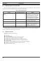
This manual contains installation and maintenance information for the Enhanced Digital Access Communications System
(EDACS) Jessica Private Branch Exchange (PBX) Gateway, known simply as Jessica. Jessica works as a centralized
subsystem within an EDACS Multisite Network to allow interconnect calls to the Public Switched Telephone Network
(PSTN) or PBX by EDACS users, as well as calls to EDACS users from the PSTN/PBX. For calls originating from a
telephone, Jessica represents a single point of entry to every site in an EDACS network.
EDACS Sites
Single Point of Entry For Routing
Telephone Calls Between the EDACS
Radio Network and the
Public Telephone Network
Level 1
SCAT
RS-422
Downlink
JESSICA
IMC/CEC
Basic EDACS
To/From PSTN
or customer PBX
Audio
Simulcast
Figure 1 - Jessica PBX Gateway Functionality
Jessica incorporates the Ericsson MD110 PBX. A default or “standard” configuration for the MD110 tailored for Jessica
is provided; however, those installing Jessica must modify the MD110 configuration to meet the customer-specific MD110
requirements. A questionnaire on the MD110 configuration (refer to Appendix A of LBI-39039) should be completed by the
customer and provided to the installer of the MD110 minimally 2 weeks in advance of the MD110 installation.
Jessica provides common telephone features (such as common speed dialing) to EDACS radio users and those persons
calling into EDACS from the PSTN. Standard ringing and busy tones are incorporated on both inbound (telephoneoriginated) and outbound (radio-originated) calls.
5
LBI-39000
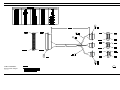
OVERVIEW
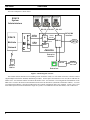
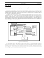
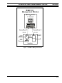
The Jessica subsystem is shown below.
S ys tem Ma na ger
EDACS
System
Administrators
RS-232
EDACS
Multisite
Network
I
M
C
P
I
M
Audio
Cards
6-Wire
RS-422
M D11 0 Term ina l
P I Adm in Term inal
RS-232
PSTN/PBX
Interface
EDACS
Interface
PI
T1/E1 ISDN
4-Wire
Audio
RS-232
MD110
T1/E1 Audio
PSTN
MUX
Jessica
Extension
Interface
EDACS
Radio
EDACS
Radios
Modem
PSTN
Extensions
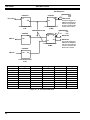
Figure 2 - Block Diagram of Jessica
This manual includes instructions for installing Jessica around the world, so it will contain references to both T1 and E1
(digital multiplexed interface standard) installation procedures. In some places the notation 23/30 is used; the 23 indicates the
number of T1 voice channels and the 30 indicates the number of E1 voice channels. The configuration and installation of the
MD110 are covered in the Ericsson documentation shown in the list that follows (documents with the BC number). A section
on configuring the MD110 is provided in LBI-39039, and a sample configuration disk is also supplied. Jessica is not a local
interconnect system associated with EDACS single-site systems. For information on local interconnect, refer to LBI-38513.
6
OVERVIEW
LBI-39000
The manuals listed below are referenced throughout this document. Some provide additional background information
and others may be useful for solving technical difficulties.
l
l
l
l
l
l
l
l
l
l
l
l
l
l
LBI-38703, System Manager Installation, Setup and Troubleshooting
LBI-38894, GETC Maintenance Manual
LBI-38938, CEC/IMC Installation, Set-up and Troubleshooting
LBI-38939, CEC/IMC Customer-Specific System Documentation Overview
LBI-38984, System Manager User’s Manual
LBI-38985, EDACS Site Controller Maintenance Manual
LBI-39001, EDACS Jessica PBX Gateway Operator's Manual
LBI-39039, EDACS Jessica PBX Gateway MD110 Configuration Manual
LBI-39040, EDACS Jessica PBX Gateway PBX Interface User's Manual
LZTU 106 1250, MD110 Technical Product Description, BC6
LZBU 106 100, MD110 Customer Library -- Small Basic, BC 6
EN/LZB 103 866, Installation MD110/50
62.6929.000.00, Equipment System PCM 30 FXM (ANT BOSCH MUX Manual)
NECA 365-454-000, Equipment Manual for ND4 Enhanced Digital Channel Bank Equipment
This manual presents system installation and maintenance information for the Jessica PBX Gateway. Section 2 describes
the Jessica components, and section 3 covers the processes that occur when a telephone call is placed. Section 4 presents
features of the system and section 5 discusses EDACS software and hardware requirements for Jessica. Section 6 covers
configuration considerations and preparations that must be completed prior to installing the Jessica equipment. Section 7
details the configuration, installation, and verification procedures to be performed when installing or adding Jessica to the
EDACS Multisite Radio Network. Section 8 presents various methods for troubleshooting technical difficulties. Section 9
contains a glossary of terms. Appendix A contains documentation on internal cable connections. Appendix B provides a
condensed listing of information applicable to the T1 Multiplexer. Appendix C includes spare parts information for the PBX
Interface, Multiplexer, and MD110. Appendix D has a LAN Network Survey that should be completed before Jessica is
installed if network connectivity is desired. Appendix E presents information on integrating the functions of the PI
administrative terminal and the MD110 configuration terminal into one management station. Appendix F contains drawings
for maintenance and reference purposes.
7
LBI-39000
COMPONENTS
2.
COMPONENTS
The primary components of Jessica are as follows:
•
•
•
•
PBX Interface (PI)
- VMEbus architecture
- PI Controller (PIC) provides interconnect call management
- Multisite Interface Controller (MIC) HDLC link to IMC Controller card
- Primary Rate Interface (PRI) T1/E1 audio to ISDN primary rate interface translation
MUX Channel Bank
- Combines 4-wire audio into single digitized audio stream
- Either T1 (23 audio channels) or E1 (30 audio channels) multiplexer
Ericsson MD110 Private Branch Exchange (PBX)
- Jessica external interface to PSTN or another PBX
- Provides full PBX functionality
- Supports a variety of both analog and digital trunk terminations
IMC PBX Interface Module (PIM)
- Provides EDACS audio path and control signaling interface to Jessica
- 1 controller card and up to 8 audio cards (4 channels per card)
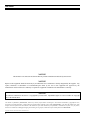
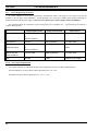
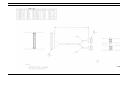
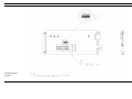
Jessica system architecture is shown below.
PI
Administrative
Terminal
PI
Hard Drive
Floppy Drive
RS-232
IMC
Control
(RS-422)
6-Wire
Termination Lines
T1/E1
MIC
PIM
Audio
(600 ohm)
4-Wire
PIC
PRI
VMEbus
ISDN
Ericsson
MD110
PBX
T1/E1
MUX
PI - PBX Interface
PIM - PI Interface Module
PIC - PI Controller
MIC - Multisite Interface Controller
PRI - Primary Rate Interface
MD110
Configuration
Terminal
Figure 3 - Jessica System Architecture
8
To PSTN or PBX
(T1/E1 or Analog)
COMPONENTS
2.1.
LBI-39000
PBX INTERFACE (PI)
The PI provides the interface between the IMC and the MD110. It is responsible for telephone interconnect call
management. The PI has a VMEbus architecture that includes three primary boards and the miscellaneous equipment below.
l
PI Controller (PIC) Board -- a single-board computer that utilizes a CISC 32-bit microprocessor. The PIC is responsible
for processing all interconnect calls. It also controls the interfaces to the floppy and hard drives through a small
computer systems interface (SCSI) port.
l
PI Multisite Interface Controller (MIC) Board -- a wide-area network (WAN) server board that provides a high-level data
link control (HDLC) link to the PIM controller board within the IMC.
l
Primary Rate Interface (PRI) Board -- provides the E1/T1 ISDN interface to the MD110 as well as the E1/T1 audio
interface to the IMC/MUX. If a T1 link is specified, a PRI-48 is used. If an E1 link is specified, a PRI-64 is used.
l
Hard Drive -- drive used for storing the application code, configuration parameters, and call activity.
l
Floppy Drive -- a 1.44 Mbyte, 3-1/2" drive for configuration parameter updates and application code upgrades.
l
VT100 administrative field terminal -- used to manipulate files on the PI via a pSOS (UNIX-like shell) terminal interface
running on the PIC.
NOTE
The functions of the PI administrative terminal and the MD110 configuration terminal may be combined into one
management station. One management station does not imply that there will be an integrated PI/MD110 entity manageable
from the Network Manager. Please see Appendix E for more information on integrating the management station.
Please refer to LBI-39040, EDACS Jessica PBX Gateway PBX Interface User’s Manual, for a detailed description of the
PI components.
9
LBI-39000
2.1.1.
COMPONENTS
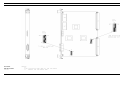
Mechanical Package
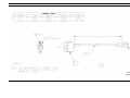
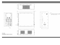
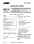
The horizontally oriented VME chassis occupies 4 rack units (RU).
IMC Control Interface
IMC Audio Interface
Audio Multiplexer
PI Electronics Assembly
Power Supply/Conditioner
Figure 4 - Rear View of the PI/MUX Cabinet
2.1.2.
Hardware Specifications
General Specifications
Interface Types
Drives
FCC Regulations
Centronics parallel printer interface
RS-232 serial interface supporting VT100 type terminals
245 or 290 Mbyte Maxtor fixed disk drive with SCSI
1.44 Mbyte, 3.5" removable diskette DOS drive with SCSI
Conforms to FCC Rules Part 15 Class A and EN 55022 Class B
Power Supply
Input Voltage (Autosensing)
Over Voltage Protection
Reverse Voltage Protection
Short Circuit Protection
Thermal Protection
Status Indicators
Duty Cycle
Redundancy
10
90-132 VAC, 47-63 Hz
180-264 VAC, 47- 63 Hz
120 to 130% of nominal output on all channels
AC "POWER ON" indicator
None
COMPONENTS
LBI-39000
Status Inputs and Outputs
Board LEDs
General Purpose CPU
MIC
PRI-48
PRI-64
Drive LEDs
Fan LED
Remote Reset Input Connector
FAIL, STATUS, RUN, and SCON
RUN, FAIL, and STATUS
RUN, FAIL, TRUNK A alarm, and Trunk B alarm
RUN, FAIL, TRUNK A alarm, Trunk B alarm, and 7-Segment SelfTest Display
Disk activity lamps on both drives
12 VDC power indicator lamp
Shorting two pins forces a system RESET
Environmental
The operating environment must be free of corrosives or contaminants such as salt water or excessive dust. The
following environmental specifications should be met:
Temperature
Operating
Non-Operating
Humidity
Storage Temperature
Operating Altitude
Shipping Altitude
0 to +40°C
-20 to 85°C
20 to 90% noncondensing (except for removable diskette drive)
-40 to +85°C
< 15,000'
< 50,000'
Diagnostics
Error Detection
System Configuration
Controlled Shutdown
2.2.
Run-time errors logged in a file for viewing or printing
Configuration files can be viewed from the VT100 terminal interface
using config -f
Using the shutdn command, the system operator can produce a graceful
system shutdown so that calls in progress are completed.
AUDIO MULTIPLEXER
The Multiplexer (MUX), also called a Channel Bank, is used to combine 4-wire balanced audio inputs from the IMC into
a single digitized stream. In North America, Japan, and Korea, the standard is a T1 multiplexer, and in Europe, Asia, and
South America the standard is an E1 multiplexer.
A single T1 allows up to 23 voice circuits to be multiplexed together. A single E1 allows up to 30 voice circuits to be
multiplexed together. Each voice circuit has its own channel unit within the MUX.
11
LBI-39000
2.2.1.
COMPONENTS
T1 MUX Specifications
The NEC MUX is used for T1 applications. Its specifications are as follows:
T1 - 23 B+D
Configured w/ 4...23 cards*
Mechanical Construction
19.2" x 19" x 12"
Weight
<59.6 lb
Power Requirements
Voltage
-44 to -56V DC (-48V nominal)
Power Consumption
34W (0.7A)
Temperature
4.4 to 38°C
Humidity
20 to 55% (without condensations)
Environmental Requirements
*Must have card for each audio line
2.2.2.
E1 MUX Specifications
The ANT BOSCH MUX is used for E1 applications. Its specifications are shown below.
E1 - 30 B+D
Configured w/ 4...30 cards*
Mechanical Construction
10.51" x 19" x 12.2"
Weight
<26.4 lb
Power Requirements
Voltage
-19 to -75V
Power Consumption
23W
Temperature
5 to 40°C
Environmental Requirements
*Must have card for each audio line
12
COMPONENTS
2.3.
LBI-39000
POWER DISTRIBUTION UNIT AND -48V POWER SUPPLY
Power Distribution Unit Specifications
The Power Distribution Unit (PDU) operates within the same environmental specifications as shown for the PI. The
operating environment must be free of corrosives or contaminants such as salt water or excessive dust. The following
environmental specifications should be met:
Temperature
Operating
Non-Operating
Humidity
Storage Temperature
Operating Altitude
Shipping Altitude
0 to +40°C
-20 to 85°C
20 to 90% noncondensing (except for removable diskette drive)
-40 to +85°C
< 15,000'
< 50,000'
-48V Power Supply Specifications
Specifications for the -48V power supply are shown below.
AC Input
100/120/220/240 VAC +10%, -13%, 47 to 63 Hz
Tolerance for 230 VAC operation is +15%, -10%
Derate output current is 10% for 50 Hz operation
-48 VDC, adjustment range is ±5% minimum
±0.05% for a 10% change
±0.05% for a 50% load change
3mV +0.05% of output voltage, peak-to-peak maximum,
all "3-terminal regulator" outputs: 3mV +0.2% peak-to-peak
maximum
Automatic current limit/foldback
0°C full rated, derated linearly to 40% at 70°C
DC Output
Line Regulation
Load Regulation
Output Ripple
Short Circuit Protection
Temperature Rating
2.4.
PI/MUX CABINET
Specifications for the PI/MUX cabinet are shown below.
Height:
Width:
Depth:
Weight:
69-1/6”
24”
24”
∼350 lb
PI Cabinet Rack Units (RU):
PI
T1 MUX
Power Supply
4 RU
11 RU or E1 MUX
4 RU
19 RU
or
4RU
6 RU
4RU
13 RU
13
LBI-39000
2.5.
COMPONENTS
MD110 LIM
The MD110 is an Ericsson Private Branch Exchange (PBX). Its primary building block is the line interface module
(LIM). The LIM performs all call processing functions. One LIM interfaces to the PI and either the Public Switched
Telephone Network (PSTN) or another PBX. It contains two to four primary switching cards which connect to a common
backplane. The backplane includes a processor bus and a device bus. The processor bus carries control data between the
device processors on the individual boards. The device bus carries voice or data to and from device boards.
In addition to the LIM, the standard MD110 has an alarm unit, an Ericsson dial-back modem for remote configuration, a
two-hour battery back-up, and up to eight on-premises extensions that allow a telephone to be directly connected to the
MD110 for testing purposes. A 386 PC for configuring the MD110 is optional.
The MD110 also has one or more termination lines to the PSTN or another PBX. All types of digital and analog trunks
and tie lines are available based on customer needs. In addition, the MD110 always has one digital ISDN T1 or E1 trunk for
connecting to the PI.
The MD110 system requires specific environmental conditions to ensure proper operation. The MD110 should not be
installed in a location where water sprinklers are present. As an alternative, Halon is the recommended fire protection system.
If static electricity is generated by the floor covering, the floor should be covered with suitable antistatic material to reduce
the risk of disturbances to the MD110.
The following normal operating and storage limits must be maintained to ensure proper MD110 operation:
Temperature range:
Recommended state:
Relative humidity range:
Recommended state:
41 to 104°F (5 to 40°C)
72 ± 2°F (22.2 ± 1.1°C)
20 to 80%
50 ± 10%
Before power is applied to an MD110 system, the equipment and the ambient room temperature/humidity must be stable
within the operating ranges. Measurements should be taken at least 60 inches above the floor and at least 20 inches from any
heat dissipating object. Typical heat dissipation for MD110 cabinets is 300W. This value recognizes that some of the power
supplied to the system rectifiers is actually dissipated over cabling and external station equipment.
The type of air filtration required for proper operation depends upon the dust and other particulate matter concentrated in
the equipment room. In a high particle-count atmosphere, use of a prefilter and a main filter in the room ventilation intake is
required. If salt air, corrosive gases, or other degrading pollutants are present, special filtering is required. Air in the
equipment room should circulate to prevent hot spots and to exhaust heated air. To be safe, circulation equipment should
change the equipment room air every 5 minutes. The circulating air should contain from 5 to 25% filtered fresh air.
Dimensions of MD110 equipment cabinets are as follows:
Height:
Width:
Depth:
62.1"
27.1"
13.4"
Floor loading is based on a 36-inch deep aisle working space in front of each cabinet and is derived from total cabinet
weight. The maximum weight of a fully loaded LIM cabinet is 440 lb. The cabinet floor loading for MD110/50 cabinets is
approximately 47.3 lb/sq ft.
2.6.
PBX INTERFACE MODULE (PIM)
Within the IMC, a PBX Interface Module (PIM) handles signaling and audio for Jessica. The PBX Interface Module
controller card can control up to eight audio cards.
14
OPERATION
3.
LBI-39000
OPERATION
Telephone interconnect calls can be initiated from an EDACS radio or from a telephone. This section describes the
processes that occur when a telephone call is placed. How a call is processed depends on whether or not B-answer
supervision is provided on the telephone lines coming into the MD110 from the PSTN or customer PBX.
3.1.
RADIO-ORIGINATED (OUTBOUND) CALLS
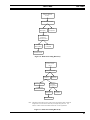
Outbound call setup is covered in Figure 5 for an MD110 configured with B-answer and Figure 6 for an MD110 not
configured for B-answer. The operation difference between MD110s with respect to B-answer is displayed in the table
below.
With B-Answer
Without B-Answer
The MD110 sends alerting to the PI. The PI requests
the IMC to generate ringing tones that are sent to the
initiating radio.
The MD110 generates its own connect to the PI and the
user listens to network ringing, rather than IMCgenerated ringing tones.
When the telephone is answered, the PSTN indicates to the MD110, which then indicates to the PI, that the party being
called has answered. The connection is now established between the originating radio and the telephone terminal, and the
conversation proceeds.
Either the telephone user or the radio user can terminate the call. If the telephone user hangs up first, the PSTN notifies
the MD110, which indicates to the Jessica PI that the telephone party has disconnected. The PI sends a drop message to the
IMC, and the message is passed to the site where the radio has been assigned a channel.
Alternately, the radio user can terminate a call by pressing the SPC or Clear key. In this case, EDACS sends the call drop
message to the IMC, which passes the drop message to the Jessica PI. On receiving the drop message, the PI disconnects the
telephone call connection to the MD110.
3.2.
TELEPHONE-ORIGINATED (INBOUND) CALLS
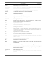
Inbound call setup is covered in Figure 7. The EDACS number plan is listed below and contains the actual digits entered
at the MD110.
Table 1 - EDACS Number Plan
00001-16382
LID (individual call)
20000-22047
GID (group call)
"2" prefix indicates GID
300001-316382
Digital LID (individual call)
"3" prefix indicates digital
320000-322047
Digital GID (group call)
"3" prefix indicates digital
"2" prefix indicates GID
A LID has 5 digits (xxxxx), a GID has the number “2” + 4 digits (2 + xxxx), and a digital call has the number “3” + 5
digits (3 + xxxxx).
The call termination is identical to the process described for radio-originated calls.
15
LBI-39000
OPERATION
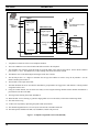
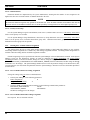
(1) User keys telephone
number
(2) Interconnect request
M-RK
(8) Radio switches to
working channel
and sends phone
digits
JESSICA
MNU
1 SYS
2 GRP
3 SCN
5
6 ADD
7 STS
8 MSG
9 DEL
*
0 DISP
4
PHN
SITE
MD110
IMC
PBX Interface (PI)
(4) Call request
(12) Digits analyzed,
trunk assigned
(else busy)
(16) Telephone
answered
(3) Deny or
queue request
(5) Channel assigned
(else busy)
(6) Port assignment
(7) Assign working
channel
(11) Call setup
performed
(10) Phone digits
sent to PI
(9) Dialed digits
sent to IMC
(14) Ringing tone
generated
(15) Ringing sent to
radio
(13) Alerting
(ringing or busy)
(17) Connect
1.
Radio user enters a telephone number then briefly presses the push-to-talk (PTT) button.
2.
A telephone interconnect request is sent to the site on the control channel.
3.
The site denies or queues the request in the trunked system.
4.
The IMC sends a call request to the Jessica PI.
5.
The PI assigns a line between itself and the IMC.
6.
The IMC assigns a port to the call.
7.
The site sends the working channel assignment to the radio over the control channel.
8.
The radio switches to the working channel and sends the telephone digits over the working channel.
9.
The site sends the phone digits to the IMC.
10. The IMC sends the phone digits to the PI.
11. The PI analyzes the call request and phone digits then requests a trunk line between itself and the MD110.
12. The MD110 analyzes the digits and routes the call to the PSTN or customer-owned PBX.
13. If the MD110 is set up for B-answer, it sends alerting to the PI, and the PI sends a ringing request to the IMC.
14. Ringing tone is generated at the IMC.
15. The site sends the ringing to the radio.
16. The telephone is answered and an off-hook is received by the MD110.
17. The audio path is enabled in the MD110, PI, and IMC and the call proceeds.
Figure 5 - Radio-Originated Jessica Call (Outbound, With B-Answer)
16
# I ND
OPERATION
LBI-39000
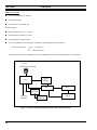
(1) User keys telephone
number
(2) Interconnect request
(8) Radio switches to
working channel
and sends phone
digits
M-RK
MNU
1 SYS
2 GRP
3 SCN
5
6 ADD
7 STS
8 MSG
9 DEL
*
0 DISP
# I ND
4
PHN
JESSICA
SITE
MD110
IMC
PBX Interface (PI)
(4) Call request
(12) Digits analyzed,
trunk assigned
(else busy)
(14) Telephone
answered
(3) Deny or queue
request
(5) Channel assigned
(else busy)
(6) Assignment
(7) Assign working
channel
(11) Call setup
performed
(10) Phone digits
sent to PI
(9) Dialed digits sent
to IMC
(13) Connect
(15) Audio path is
completed
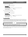
1.
Radio user enters a telephone number then briefly presses the push-to-talk (PTT) button.
2.
A telephone interconnect request is sent to the site on the control channel.
3.
The site denies or queues the request in the trunked system.
4.
The IMC sends a call request to the Jessica PI.
5.
The PI assigns a line between itself and the IMC.
6.
The IMC assigns a port to the call.
7.
The site sends the working channel assignment to the radio over the control channel.
8.
The radio switches to the working channel and sends the telephone digits over the working channel.
9.
The site sends the phone digits to the IMC.
10. The IMC sends the phone digits to the PI.
11. The PI analyzes the call request and phone digits then requests a trunk line between itself and the MD110.
12. The MD110 analyzes the digits and routes the call to the PSTN or customer-owned PBX.
13. If the MD110 is not set up for B-answer, the MD110 generates its own connect to the PI, the audio path is enabled, and
the radio user listens to network ringing, rather than IMC-generated ringing tones.
14. The telephone is answered and an off-hook is received by the MD110.
15. The audio path is completed and the call proceeds.
Figure 6 - Radio-Originated Jessica Call (Outbound, Without B-Answer)
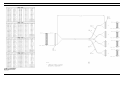
17
LBI-39000
OPERATION
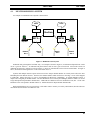
MD110
(1) Dial Jessica
(3) Enter
destination
(LID/GID)
(2) Ringing detected/
dial tone generated
M-RK
MNU
1 SYS
2 GRP
3 SCN
5
6 ADD
7 STS
8 MSG
9 DEL
PHN
0 DISP
4
*
# I ND
(11) Ringing heard at radio
(12) First PTT
PBX Interface (PI)
(4) Trunk channel
assigned (else
busy)
IMC
(5) Digits analyzed
(6) Call request
performed
(9) Alerting (ringing
or busy)
(7) Call routing
to site(s)
(else
timeout)
(10) Ringing
tone
generated
SITE
(8) Channel
assignment
(13) Channel
assignment PTT
(14) Connect
JESSICA
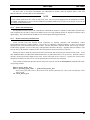
1.
Telephone user dials one of the Jessica telephone numbers.
2.
The Jessica MD110 receives the call and sends dial tone back to the telephone.
3.
The telephone user enters the logical ID (LID) or group ID (GID) of the radio(s) being called. See the EDACS number
plan in Table 1. Note: The MD110 may require routing codes before the LID is entered.
4.
The MD110 receives the dialed digits and assigns a trunk line to the PI.
5.
The PI analyzes the 5 or 6 digits to determine the call type and whether it needs to strip off any numbers. See the
EDACS number plan in Table 1.
6.
The PI sends a call request to the IMC.
7.
The IMC identifies the site or sites that the individual or group members are logged on to and initiates a working channel
assignment at those sites.
8.
Using the control channel, the site directs the radio(s) to the assigned working channel and the channel confirmation is
passed back to the PI via the IMC.
9.
The PI generates alerting to the IMC and MD110.
10. When the IMC receives alerting, it generates ringing which is sent to the radio(s) of the LID or GID being called.
11. The radio starts to ring.
12. A radio users responds by depressing the push-to-talk (PTT) button.
13. The channel assignment PTT is received by the site and sent to the IMC and the PI.
14. The audio path is enabled in the IMC, PI, and MD110, and the call proceeds.
Figure 7 - Telephone-Originated Jessica Call (Inbound)
18
FEATURES
4.
LBI-39000
FEATURES
The features of Jessica can be grouped into two classes: system features and radio user features. A list of the features in
each class is given below.
System Features
l
Basic centralized telephone interconnect, with inbound and outbound calls supported.
l
Up to 30 simultaneous calls for European, Asian, and South American systems with a digital E1 link. Up to 23
simultaneous calls for North American, Japanese, and Korean systems with a digital T1 link.
l
Encrypted voice calls.
l
Full duplex telephone calls.
l
MD110 allowance of multiple interfaces to the PSTN/PBX.
l
Automatic line clearing.
l
Authorization code disable for inbound calls (optional).
l
Activity Reports showing operational PI call activity. These reports are recorded to disk and can be redirected to debug
port 2 of the PI. Since flow control is not possible on the debug port, information will be dropped if the PI’s port 2 buffer
fills up.
l
Remote debug/code upgrades over LAN connection.
l
LAN Connectivity -- FTP, NFS, and Telnet can be used to access the PI activity reports and configuration information.
l
Direct inward dialing (DID).
l
Common speed dialing (MD110 feature).
l
Least-cost routing (LCR).
l
Optional Voice Mail.
l
System Manager Interface (individual call restrictions, no site activity monitor).
l
Priority Service Channels (dedicated lines/priority lines).
l
Site-Based Call Routing: Call routing based on originating site.
l
Rotating/First Available PI-IMC channel assignment.
l
Caller ID on outbound calls.
19
LBI-39000
FEATURES
Radio User Features
l
Call Forwarding (Busy/No Answer).
l
Last Number Redial.
l
Do Not Disturb on inbound calls.
Jessica supports:
l
Full 16382 EDACS Users (1...16382)
l
Full 2048 EDACS Groups (0...2047)
l
Failsoft and Site Controller modes
l
Up to 30 simultaneous conversations (23 maximum in North America, Japan, and Korea)
Jessica is purchased as:
4,8,12,...,23-channel T1
or
4,.......,28,30-channel E1
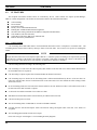
An example Jessica system, including the new System Manager Interface and Voice Mail System, is shown below.
Jessica
Administrative Terminal
System
Manager
Jessica
IMC
Site 1
Voice Mail
Leased T1/
DID lines
PC for
Admin only
Site 30
Figure 8 - Jessica with System Manager Interface and Voice Mail System
20
FEATURES
4.1.
LBI-39000
MULTINODE JESSICA SYSTEM
An example of a multinode Jessica System is shown below.
PSTN
PSTN
JESSICA B
JESSICA A
StarGate
IMC A
IMC B
Dispatch
EDACS
Site 1
Dispatch
EDACS
Site 2
EDACS
Site 3
EDACS
Site 4
Figure 9 - Multinode Jessica System
Outbound calls go through the local IMC only. For example as shown in Figure 9, an outbound call placed from a radio
on site 1 goes out Jessica A. An outbound call placed from a radio on site 4 goes out Jessica B. If Jessica B is down, an
outbound call from site 4 will not be routed to Jessica A. However, inbound calls can be routed to remote IMCs. In Figure 9
above, an inbound call through Jessica A will reach a radio on site 4.
Systems with multiple Jessicas require each Jessica to have unique channel numbers to correctly track calls to the same
LID/GID placed on different Jessicas. Therefore, the channel numbers which used to be in the range 1 to 30 will be mapped
to valid LIDs. LIDs in the range 1 to 511 are recommended for BCU/CAL compatibility. To support multiple Jessicas, a
unique LID is assigned per PI-IMC channel. The Line Definition screen of the System Manager (shown in Table 5) is used to
assign and upload unique PI-IMC channel LIDs. Valid LIDs are added into the Line Definition screen (line 1 in the Line
Definition screen corresponds to PI-IMC channel 1). Each PI must have unique PI-IMC channel LIDs.
Radio-enabled features are on a per PI basis. If the radio roams to territory covered by a different PI, then the radio user
must initiate desired features from that PI as well.
21
LBI-39000
4.2.
FEATURES
PI FEATURES
The telephone interconnect features below are controlled by the PI. Some features also require System Manager,
MD110, or radio configuration. The features are discussed in detail in the subsections that follow.
l
l
l
l
l
l
l
l
l
4.2.1.
Call forwarding.
Do not disturb.
Last number redial.
Priority service channels/dedicated lines.
Rotating/first available PI-IMC channel assignment.
Site-based call routing (includes PI and MD110 configuration modifications).
Call validation (toll call restrictions).
Caller ID provided to the MD110 on outbound calls.
Remote connectivity administration.
Call Forwarding
Call forwarding allows individual radios to forward inbound interconnect calls to a telephone or to another radio. Call
forwarding must be enacted from a radio by entering a feature code at the radio. See section 4.3 for specifics on enabling this
feature.
NOTE
All input from the radio to the Jessica System requires that the “*” button be pressed according to the requirements specified
in the radio user’s manual. If the feature code sequence is accepted, a short burst of ringing tone is heard. If the feature code
sequence is rejected, a short burst of busy tone is heard. (A short burst is defined as 5 seconds.)
Call forwarding functions according to the following rules:
l
Call forwarding to a radio causes the radio frequency (RF) channel to the first radio to be released and an RF channel to
the forwarded radio to be requested.
l
Call forwarding to a phone requires that second PI-to-MD110 channel be allocated.
l
Call forwarding loops are checked as the forwarding chain is followed and disallowed by the PI. (If the user has a car
radio and a portable radio, the user could forward each to the other and receive calls without the caller needing to know
which unit is in use.)
l
In call forwarding chains, the first radio in the chain is billed for the call, and the first radio’s call restrictions are used if
the last radio in the chain forwards to a phone.
l
A call can be forwarded a maximum of five radios in a chain.
l
Individual call forward and common call forward may be enabled at the same time.
l
Call forward setup survives reboot.
l
The call forwarding status of LIDs/GIDs is viewable via the dbv command.
l
Forwards between full and half duplex radios and between analog and digital radios with clear voice modes are
acceptable.
l
The forwarding phone number is limited to 15 digits.
Please refer to Figure 10 and Figure 11 for forwarding hierarchy diagrams.
22
FEATURES
LBI-39000
R a d io F o rw a rd a n d
C om m on F o rw a rd
Set Up
Invo ke R a dio F orw a rd
F o rw a rd e d
R a d io B usy
F o rw a rd
C om p leted
Im m e d ia te ly
F o rw a rd to
C om m on N umber
Common
N u m b er B u sy
F o rw a rd
C om p leted
C a ll D isco n ne cts
Figure 10 - Radio Forwarding Hierarchy
Pho ne F orw ard and
C om m on F orw ard
S et U p
In voke P hone F orw ard
F orwa rded
Pho n e B u sy
B -A nswe r n ot p re se n t
Forw ard
Com pleted
Im m ed ia tely
F orw ard to
C om m on N um b er
C all D isco n nects
C om m o n
N um b er Bus y
F orwa rd
Co mp leted
C all D isco nnects
N ote: If th e MD 110 trun k tha t th e call is rou ted o n does not have B-An swer, the MD 110
will ge nerate a connect w hen it s en ds the pho ne dig its a long the trunk. The
com m o n num ber cannot be fo rw ard ed to after the con nect is gen erated.
Figure 11 - Phone Forwarding Hierarchy
23
LBI-39000
FEATURES
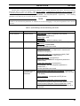
The user can select one of two forms of call forwarding: busy/no answer or do not disturb (DND). The table below
shows the results of the two forms.
Table 2 - Call Forwarding Results
Condition
Results
Busy/No Answer
Calls are forwarded if the called party is busy or does not answer
within a specified timeout. The timeout is specified via the parameter
FORWARD_NO_ANSWER_TIME in CONFIG.DAT.
Do Not Disturb
Calls are immediately forwarded without ringing the radio.
NOTE
If the System Manager interface is present, LIDs should be inbound enabled, outbound enabled, and valid at the Jessica site.
4.2.1.1. Call Forwarding Radio
Call forwarding radio allows radio users to forward inbound interconnect calls to another radio. This feature is enabled
by a feature code sequence issued at the radio. See section 4.3 for specifics on enabling this feature. If the feature code
sequence is accepted, the user hears a short burst of ringing tone. If the feature code sequence is rejected, the user hears a
short burst of busy tone.
4.2.1.2. Call Forwarding Telephone
Call forwarding telephone allows radio users to forward inbound interconnect calls to the MD110 extension or to the
PSTN. This feature is enabled by a feature code sequence issued at the radio. See section 4.3 for specifics on enabling this
feature. If the feature code sequence is accepted, the user hears a short burst of ringing tone. If the feature code sequence is
rejected, the user hears a short burst of busy tone.
4.2.1.3. Call Forwarding Common
Call forwarding common allows radio users to forward inbound interconnect calls to an MD110 extension or to the
PSTN. This feature is enabled by a feature code sequence issued at the radio. See section 4.3 for specifics on enabling this
feature. If the feature code is accepted, the user hears a short burst of ringing tone. If the feature code is rejected, the user
hears a short burst of busy tone. An example of common forwarding numbers might be a secretary, an answering service, or a
voice mail system; up to three common forwarding numbers may be defined by the system administrator using a configuration
file on the PI.
The three common forwarding numbers are specified in file PBXFEAT.DAT which is read at system boot. See LBI39040 for the creation format of PBXFEAT.DAT and set the following parameters:
COMMON_FORWARD_1
COMMON_FORWARD_2
COMMON_FORWARD_3
24
PHONEA
PHONEB
PHONEC
FEATURES
4.2.2.
LBI-39000
Do Not Disturb and Busy/No Answer
The do not disturb feature allows a radio to disable inbound interconnect individual calls. Do not disturb does not
prevent inbound interconnect group calls. If call forwarding is enabled, inbound calls will be forwarded immediately. If call
forwarding is not enabled, calls will be terminated and the caller will hear busy tone. See section 4.3 for radio-based enabling
of features.
There is a single feature code to toggle between do not disturb and busy/no answer. This feature code is unique because
the tones heard by the user have a different meaning from those in the other feature codes. If do not disturb is enabled, the
user hears a short burst of ringing tone. If busy/no answer is enabled, the user hears a short burst of busy tone. See section
4.3 for radio-based enabling of features.
4.2.3.
Last Number Redial
This feature makes it possible for a radio user to reach the last phone number dialed by entering the appropriate feature
code. The last number dialed is saved in volatile RAM and does not survive a reboot. If there is no last phone number dialed
stored in RAM, an error tone is sent to the radio user. See section 4.3 for radio-based enabling of features.
4.2.4.
Priority Service Channels
The optional priority service channels feature is used to reserve PI-IMC channels for high priority users. These reserved
channels make it more likely that high priority users will be able to place an interconnect call. However, high priority users
must still contend for RF channels, PI-MD110 channels, and PSTN lines to successfully place or receive an interconnect call.
Dedicated lines are achieved by reserving one line per dedicated user at the highest priority level. See section 4.2.4.3 for
enabling of priority service channels at the System Manager.
4.2.4.1. Priority Lines
Channel priority is implemented in the PI by assigning a priority level to LIDs/GIDs. Up to eight priority levels (0-7) are
supported, with 0 having the lowest priority. The LID/GID priority level is assigned at the System Manager. On
powerup/restart, the disk file PRIORITY.DAT assigns the number of channels per priority level. Each priority level may
have different numbers of channels. Interconnect calls are allocated channels designated for their priority, if available. If no
channels are available in their priority level, the next lower priority level is checked.
Priority channels functions according to the following rules:
•
The algorithms below are used by the priority service channels code.
If LID/GID Database Present
Use priority level of LID/GID as sent in the priority level field from the
System Manager as the requested priority.
else
Use highest LID/GID priority level for the request priority.
Channels_Pool = (MUX_CHANNELS_MASK & IMC_CHANNELS_MASK)
•
If the number of channels in Channels_Pool is not equal to the number of channels specified in PRIORITY.DAT, the
channels will be added/subtracted from the lowest available priority level.
•
If PRIORITY.DAT does not exist, all channels will be allocated to the lowest priority level. See LBI-39040 for
PRIORITY.DAT format.
•
Inbound group calls are allocated according to the priority level assigned to the group.
25
LBI-39000
FEATURES
4.2.4.2. Dedicated Lines
Dedicated channels are implemented by the system administrator, ensuring that the number of users assigned to the
highest class does not exceed the number of channels allocated to the class.
NOTE
This dedicated channel arrangement only guarantees the PI-IMC link. Since the MD110 handles the PI-MD110 link and call
redirection can use two PI-MD110 channels, there is still the possibility of being blocked even at the highest priority level.
4.2.4.3. Priority Level Setup
Use the System Manager Logical Unit Definition, menu item 11, Radio Features screen 2:3 Call Priority: Interconnect
field to set the priority level of radios.
Use the System Manager Group Identification, menu item 12, Group Parameters screen 2:3 Call Priority: Interconnect
field to set the priority level of inbound interconnect group calls. Outbound interconnect group calls are not possible.
Inbound interconnect group calls are possible.
4.2.5.
Rotating/First Available Channel Assignment
This feature allows the user to select either rotating (balanced loading) of IMC PIM audio channels or first available.
Descending channel assignments are available only with rotating assignments enabled. Ascending channel assignments are
available with both rotating and first available assignments available.
Channel assign usage may be specified from either the System Manager or the PI administrative terminal. In the System
Manager (screen 2:4 Site Parameters), changes are made by modifying the Rotate Assignments and Assign Channel
Ascending parameters. From the PI terminal, changes are made by using the config -s command to edit the CONFIG.DAT
parameters ROTATING_ASSIGNMENTS and ASSIGNMENT_ORDER (shown in LBI-39040) and then using the savecfg
command to save the changes. The System Manager method does not write the parameter changes to the PI hard drive; thus,
on each reboot the user must obtain the parameters from the System Manager, otherwise Jessica uses the default parameters
stored in the PI.
4.2.5.1. First Available Channel Ascending Assignment
Change the settings using one of the two methods below.
1.
In the System Manager, set the following parameters:
Rotate Assignments
N
Assign Channel Ascending
Y
2.
Using the config -s command at the PI terminal, set the following CONFIG.DAT parameters:
ROTATING_ASSIGNMENTS
FALSE
ASSIGNMENT_ORDER
ASCENDING
and then use savecfg to save the changes.
4.2.5.2. First Available Channel Descending Assignment
Not an option. This is consistent with sites.
26
FEATURES
LBI-39000
4.2.5.3. Rotating Channel Ascending Assignment
Change the settings using one of the two methods below.
1.
In the System Manager, set the following parameters:
Rotate Assignments
Y
Assign Channel Ascending
Y
2.
Using the config -s command at the PI terminal, set the following CONFIG.DAT parameters:
ROTATING_ASSIGNMENTS
TRUE
ASSIGNMENT_ORDER
ASCENDING
and then use savecfg to save the changes.
4.2.5.4. Rotating Channel Descending Assignment
Change the settings using one of the two methods below.
1.
In the System Manager, set the following parameters:
Rotate Assignments
Y
Assign Channel Ascending
N
2.
Using the config -s command at the PI terminal, set the following CONFIG.DAT parameters:
ROTATING_ASSIGNMENTS
TRUE
ASSIGNMENT_ORDER
DESCENDING
and then use savecfg to save the changes.
4.2.6.
Site-Based Call Routing
The MD110 and the PI both control portions of site-based call routing. The PI controls site-based call routing via the
configuration parameter SITE_ROUTING_ENABLE (this parameter is enabled when set to TRUE), and prepends 3 routing
digits used by the MD110, but the MD110 performs the actual call routing (see LBI-39040). The MD110 removes the
prepended digits and routes the call to the appropriate trunk using Route Destination Codes (DEST). There are limitations in
the MD110 as to how discriminating the routing based on the called number can be since the tables used were designed for
one or a few codes, and are now divided for 32 sites.
NOTE
The PI hardware limits the maximum number of digits to 17. If site-based routing is enabled, then the maximum number that
can be entered at the radio is 14 digits since 3 digits are prepended for the total of 17 digits.
Outbound calls contain information about the originating EDACS site. The PI prepends a user-defined routing digit (0-9)
(SITE_ROUTING_PREFIX parameter defined in CONFIG.DAT -- default of 6) followed by a 2-digit originating EDACS
site ID (01-32). The MD110 can use up to five digits of the incoming number to determine call routing. Since three of these
digits are prepended by the PI (one digit to indicate the routing tables and two digits to indicate the originating site), two
digits of the incoming number are analyzed.
27
LBI-39000
FEATURES
To allow the greatest flexibility in programming the MD110, the PI algorithm allows flexibility in prepending digits when
3-digit numbers are encountered.
The algorithm for prepending digits is as follows:
switch (num digits in number)
{
case 4: /*possible MD110 extensions*/
case 5:
break;
case >5:
case <3:
prepend digits;
break;
case 3: /*possibly 911 etc*/
if (SBR_FOR_3_DIGITS config param)
prepend digits;
break;
}
4.2.7.
Toll Call Restriction (Call Validation)
NOTE
ALLOW.DAT, DISALLOW.DAT, LID.DAT, and GID.DAT must be present in the PI for the PI to perform toll call
restrictions.
Jessica allows 16 classes of interconnect users (0-15). Users in class 15 are permitted to call any number. Users in
classes 0-14 must first be routed through the allow table and the disallow table to determine whether their class is permitted to
make a call. When the call restrictions feature is enabled by the CALL_NUM_RESTRICTIONS parameter (see LBI-39040),
any number called by the user must be explicitly permitted in the allow file and must not be denied in the disallow file.
The following algorithm is used for call validation:
if (LID/GID database present)
if (LID/GID valid and inbound/outbound enabled)
case OUTBOUND:
if ((CALL_NUM_RESTRICTIONS == TRUE) && (! class == 15))
if (ALLOW.DAT missing)
Deny all calls
else
Deny/allow calls as specified in ALLOW.DAT and DISALLOW.DAT
else
Allow call
case INBOUND:
Allow call
else
Deny call
else
if (CALL_NUM_RESTRICTIONS == TRUE)
Deny all calls
else
Allow all calls.
28
FEATURES
LBI-39000
The allow table is read from ALLOW.DAT (see LBI-39040 for details), while the disallow table is read from
DISALLOW.DAT (see LBI-39040 for more information).
NOTE
If a file contains syntax errors, the entire file will not be used. The error will be flagged to the PI administrative terminal.
The callres command may be used to check ALLOW.DAT and DISALLOW.DAT for syntax errors and may be used to test
the validity of individual numbers.
4.2.8.
Radio Caller Identification
On outbound interconnect calls, if the CALLER_ID CONFIG.DAT parameter is TRUE (see LBI-39040), the LID of the
radio originating the call will be passed to the MD110 in the call setup signaling and may be displayed on phones with a
digital display. The connection from the MD110 to an external phone must support caller ID.
4.2.9.
Remote Connectivity Administration
Jessica provides local area network (LAN) connectivity by allowing computers with Transmission Control
Protocol/Internet Protocol (TCP/IP) facilities. The PI may be completely configured remotely via the LAN connection
supporting FTP, Telnet, and Network File Server (NFS). For FTP and Telnet to function, IP.DAT must be set up correctly.
In LBI-39040, Appendix A covers Telnet usage, and Appendix B describes FTP usage. Appendix D herein contains a LAN
Network Survey that should be completed before Jessica is installed if network connectivity is desired.
NFS allows users to mount file systems located across the network and use them as part of their own file system. To use
NFS, EXPORTS.DAT (see LBI-39040) and ROUTES.DAT (see LBI-39040) must be set up correctly. Directories must be
explicitly exported by the host computer to the client. Jessica will be able to act as a host (i.e., export its file system to other
computers) but shall not be able to act as a client and mount file systems from other computers.
From a UNIX workstation on the same network as the Jessica system, execute the mount/umount commands with superuser privilege enabled.
mkdir local_mount_dir
mount jessica_host_name: / path/local_mount_dir
where jessica_host_name refers to the IP name of the Jessica connection and / refers to the root directory on the
Jessica system.
cd local_mount_dir
29
LBI-39000
4.3.
FEATURES
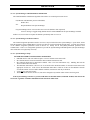
RADIO-ENABLING OF FEATURES
This section discusses the settings necessary to activate those features that may be enabled from a radio. In the table
below, FCP is used for the CONFIG.DAT parameter FEATURE_CODE_PREFIX.
Table 3 - Radio-Enabled Features
Feature
From LIDA, enter FCP
Result
Busy/no answer toggle to do not
disturb
FCP-04
Toggles between busy/no answer and
do not disturb. The user hears a short
burst of ringing when do not disturb is
enabled, and a short burst of busy
tone when busy/no answer is enabled
(and do not disturb is not enabled).
Call forwarding radio
FCP-03-LIDB
Forwards LIDA’s radio to LIDB. The
LID must be a 5-digit number.
Call forwarding telephone
FCP-02-PHONEA
Forwards LIDA’s radio to PHONEA.
Call forwarding common
FCP-01-1
Forwards LIDA’s radio to COMMON
NUMBER 1, which was defined as
PHONEA in PBXFEAT.DAT.
Last number redial
FCP-05
Calls the last phone number dialed.
To disable a feature, enter the FCP and the two digits that immediately follow it, but do not enter the arguments. For
example, to disable call forwarding common, enter FCP-01.
4.4.
MD110 FEATURES
The MD110 provides the following features:
l
l
l
l
l
l
l
l
l
l
30
Voice mail.
Caller identification.
Site-based call routing (PI and MD110 both control portions).
Analog or digital interfaces to the PSTN or another PBX.
Routing of PSTN-originated calls to EDACS or to MD110 extensions.
Routing of EDACS-originated calls to the PSTN or to MD110 extensions.
Least-cost routing.
The ability to dial any radio ID from the PSTN with analog end-to-end signaling.
Dialing restrictions on calls from EDACS or MD110 extensions.
Direct inward dialing to radios.
FEATURES
4.4.1.
LBI-39000
Voice Mail
Ericsson Business Networks can provide VMX Systems Inc. voice mail equipment with the MD110. A VMX100 6-port
system is presented here as an example. Each port is equivalent to an analog phone line. The VMX100 also requires one
MD110 control connection.
Voice mail is accessed either by a direct call to the group hunt MD110 extension (2100 in the example) or by an
individual or common call forward from a radio (to 2100). The user enters the top level of the voice mail system and is
prompted to enter the mailbox number. The LID must be entered without the leading zeros. (The text string from VMX can
state “Please enter the LID without the leading zeros.”)
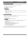
The MD110 requires three new cards for voice mail: Information Computer Unit (ICU), Extension Line Unit (ELU) 24,
and Serial Filter Unit (SFU). The ICU connects the RS-232 control data channel from the VMX system to the MD110. The
ELU24 is a 7-analog-channel card. The SFU is a line filter card. The VMX100 is connected to 6 of the 7 analog ports. The
TRS9010405/1100 is a generic cable. The three cables between the LFU and the Punch Block are distributed as follows: two
for voice mail and one for Caller ID phone. These cables may be run from the same LFU or different LFUs, depending on the
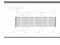
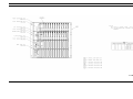
number of lines required. Please refer to Figure 12.
TRS90104050/1100
(3)TRS9010405/1100
ELU25
LFU
Punch
Block
V M X 1 00
TSR9010405/2300
ELU24
ICU
Ports
1-6
RJ11
Breakout
Box Ext
2101 - 2106
TSR9020438
MD110
SFU
25-Pair Telco Cable
D igita l P hon e
TERM2
TSR9020404/10000
IPU
SCSI
TERM1
S C S I Serial Port
PC
Figure 12 - Voice Mail Setup
The suggested LID range for VMX mailboxes is 2000 to 16382 However, the algorithm for mailbox allocation is
flexible and is outlined as follows. The first mailbox defined casts the number width of all mailboxes starting with the same
first digit. Therefore, if mailbox number 16000 is defined, then mailbox 1000 is not possible -- all mailboxes starting with 1
must be 5 digits wide. Likewise, if mailbox 300 is defined, then mailbox 3005 is not possible because all mailboxes starting
with 3 are 3 digits wide. The minimum mailbox number width is 2 digits.
31
LBI-39000
4.4.2.
FEATURES
Caller ID on Outbound ISDN Calls
See LBI-39040 for information on enabling this feature. If the feature is desired on a local MD110 extension, the
following hardware may be installed in/on the MD110 as shown in Figure 12.
1 digital telephone (DBC 661 002/001)
1 digital extension board (ELU25 ROF1375306/2)
4.4.3.
Site-Based Call Routing
Outbound calls can be routed based on the originating radio site. The MD110 and the PI both control portions of sitebased call routing. The PI controls site-based call routing via a new configuration parameter (SITE_ROUTING_ENABLE,
which is enabled when set to TRUE), but the MD110 performs the actual call routing.
The MD110 can use up to five digits of the incoming number to determine call routing. Three of these digits are
prepended by the PI (1 to indicate the routing tables and 2 to indicate the originating site). Two digits of the incoming
number are analyzed. Outbound calls contain information about the originating EDACS site. The PI prepends a user-defined
routing digit (0-9) (SITE_ROUTING_PREFIX parameter defined in CONFIG.DAT -- default of 6) followed by a 2-digit
originating EDACS site ID (01-32).
The MD110 removes the prepended digits and routes the call to the appropriate trunk using Route Destination Codes
(DEST). There are limitations in the MD110 as to how discriminating the routing based on the called number can be since
the tables used were designed for one or a few codes, and are now divided for 32 sites. The DEST routing table can support
500 entries. Please refer to LBI-39039 for an example of site-based routing.
4.4.4.
Call Validation MD110 Modifications
Early Jessica installations with no System Manager interface that are being upgraded to include a System Manager
interface require that global toll call restrictions be removed. Many early Jessica MD110 installations were configured to
prevent long distance numbers by limiting the digit length of outgoing numbers in their least-cost routing tables. Other
MD110s may have least-cost routing tables to restrict calls. Refer to actual MD110 programming to determine how to
remove toll call restrictions.
4.4.5.
Enabling Inbound Phone Digits from the MD110
Please refer to LBI-39039 for specifics on MD110 programming.
32
SYSTEM REQUIREMENTS
5.
5.1.
LBI-39000
SYSTEM REQUIREMENTS
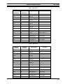
EDACS SOFTWARE REQUIREMENTS
Minimum EDACS software revision levels compatible with Jessica are shown below. All features may not be available
with the software versions shown below. Refer to Jessica Release Notes for feature compatibility.
Table 4 - EDACS Component Software Version Requirements
Platform
PBX Interface (PI)
Minimum Software Version
1.
Networks/Data VME Controller 349A9983Gx
2.
PI Application 349A9982Gx
See Release Notes 349A9982Px for features available per
release.
MD110
CEC/IMC
1.
MD110 Software BC 6.2.1G
2.
Configuration File 349A9986G1
1.
IMC Controller Board
U3 344A3565G10
U58 344A3567G10
U59 344A3568G10
U3 344A3565G7, C3 XLTR only
U58 344A3569G4, C3 XLTR only
U59 344A3570G4,C3 XLTR only
2.
IMC Audio Board
U99 344A3564G10
3.
Conventional Interface Audio Board
19D903324P1
U13 344A3694G10
4.
CEC/IMC Manager
Disk 344A3630G10
Multinode Jessica Systems require IMC Version 5.x.
C3 Maestro
1.
Disk 344A3922G10
2.
CLB U4 344A4245G10
VAX System Manager
344A4583G3
GETC-1E CC/WC Main Board
Link1 GETC UL/DL Main Board
U2 349A9607G2
U2 344A4895G1
GETC Turbo Board
Disk 344A4414G3
GETC Turbo Loader (PC)
Disk 344A4414G3
SCAT GETC and SCAT/DL
U2 344A3835G1
1
Uplink does not use the Turbo board.
33
LBI-39000
SYSTEM REQUIREMENTS
Table 4 - EDACS Component Software Version Requirements (Cont.)
Platform
DVIU VGE
Minimum Software Version
1.
344A4516G4
2.
Voice Guard
344A3000P91
Aegis
344A3000P290
Unencrypted Aegis
344A3000P490
DVIU DES
1.
344A4513G3
2.
Voice Guard
344A3000P41
Aegis
344A3000P240
Unencrypted Aegis
344A3000P440
M-PA radio
EDACS 344A4614G12
EDACS 19A149863G12
EDACS DES 344A3703G12
EDACS VGE 344A3705G12
EDACS Aegis 344A4415G12
EDACS Aegis DES 344A4419G12
EDACS Aegis VGE 344A4421G12
M-RK radio
M-RK 1 Version 1 hardware
344A4862G11
M-RK 1 Version 3 hardware
349A9842G11
M-RK 2 Version 2 hardware
344A4716G10
M-RK 2 Version 3 hardware
349A9845G10
Orion radio
34
344A4893G10
SYSTEM REQUIREMENTS
5.2.
LBI-39000
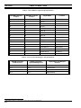
EDACS HARDWARE REQUIREMENTS
Jessica requires the EDACS hardware revision levels shown below to support the software revision levels presented in
the preceding section.
5.2.1.
System Manager Requirements
Hardware
Hardware Revision
VAX System Manager
See Software Release Notes
349A9942.
Cable for System Manager
149575P18 (10 ft)
149575P19 (25 ft)
149575P20 (50 ft)
5.2.2.
Site Controller Requirements
Hardware
VAX Site Controller
Hardware Revision
19A149302P8 for Europe
19A149302P5 for US
The PDP Site Controller and PDP System Manager do not support Jessica.
5.2.3.
IMC Requirements
Hardware
Controller Board
Hardware Revision
Rev. G or later for 19D903299P1 on all but the PIM
or
any rev. for 19D903299P3 on all including the PIM
Audio Board
Rev. H or later for 19D903302P1
or
any rev. for 19D903302P3
Clock Board
Rev. E or later
N. America may use Rev. D or later
MOM PC
NA
35
LBI-39000
5.2.4.
SYSTEM REQUIREMENTS
GETC Requirements
The following three GETC categories differ in that not all use the Turbo option, and the three do not share common
software.
5.2.4.1. GETC 1-E Control/Working Channel Requirements
Hardware
Control/Working Channel
Turbo
Yes
Hardware Revision
Rev. F or later for 19D902104
or
any rev. of 19D904266
5.2.4.2. Link GETC Uplink/Downlink Requirements
Hardware
Downlink
Turbo
Yes
Hardware Revision
Rev. F or later for 19D902104
or
any rev. of 19D904266
Uplink
No
Rev. F or later for 19D902104
or
any rev. of 19D904266
5.2.4.3. SCAT GETC Requirements
Hardware
SCAT
Turbo
Yes
Hardware Revision
Rev. F or later for 19D902104
or
any rev. of 19D904266
5.2.5.
Jessica Requirements
5.2.5.1. MD110 Requirements
Please refer to LBI-39039, EDACS Jessica PBX Gateway MD110 Configuration Manual, for MD110 requirements.
5.2.5.2. PI Requirements
The PI requirements are as follows:
T1
•
MUX and MD110 connection ports are 100 ohm balanced.
E1
•
36
MUX and MD110 connection ports are 120 ohm balanced.
SYSTEM REQUIREMENTS
LBI-39000
5.2.5.3. MUX Requirements
The MUX provided with Jessica meets the following requirements:
T1
•
•
•
•
•
•
•
•
•
23 channels of balanced 600 ohm 4-wire audio (no signaling required).
1.544 Mb/s 100 ohm aggregate interface.
T1 framing is extended superframe (ESF).
T1 line coding is B8ZS.
120 VAC 50/60 Hz or 240 VAC 50/60 Hz is preferred.
The unit will mount in a 19-inch rack.
CCITT: G.703, G.704, G.711 (u-Law), G.733, G.734, and G.824.
FCC Part 15 Class B approval is required.
CSA and UL approval are required.
E1
•
•
•
•
•
•
•
5.2.6.
30 channels of 4-wire balanced 600 ohm audio (no signaling required).
2.048 Mb/s 120 ohm impedance aggregate interface.
HDB3 line coding.
CCITT: G703, G704, G711 (A-Law), G732, G736, and G823.
CISPR22: EN 55022.
IEC: 801-2, 801-3, 801-5; EN 60950 per 950.
The unit will mount in a 19-inch rack.
RF Repeater Requirements
The equipment may be EDACS MASTR II, MASTR IIe, or MASTR III.
5.2.7.
Radio Requirements
A radio must support digital interconnect dialing. Interconnect must be enabled on each particular radio.
5.2.8.
Radio Requirements for DTMF
Dual tone multi-frequency (DTMF) tone sending capability, while connected to a called party, is necessary for special
functions, such as voice mail access.
The radio must be programmed with the settings below (minimal values) for the MD110 to detect the DTMF digits
generated by the radio.
Option
Minimum Range
0-9 (tone length)
70 ±5 ms
*,# length
70 ±5 ms
Interdigit delay
70 ±5 ms
37
LBI-39000
5.2.9.
SYSTEM REQUIREMENTS
Power Requirements for Jessica
AC power (adequate to meet system requirements, environmental control, and digital or voice grade lines) must be
available to the site prior to the installation. An unterminated power cord and a standard three-prong ground plug are
furnished for the PI cabinet power supply. Check to be sure that the power outlet complies with local ordinances.
The equipment should be connected to a good earth ground wire of adequate size. A ground stud is provided for a
separate cabinet ground.
Voltage Requirements
PI
110 VAC 50/60 Hz
Power Requirements
Power Source
150-200W
Cabinet Power Supply
or
220 VAC 50/60 Hz
Terminal for PI
110 VAC
70W (estimated)
110 VAC outlet
MD110
110 VAC 50/60 Hz
300W (typical)
110 VAC or 220 VAC
(model /10 or /50)
or
outlet
220 VAC 50/60 Hz
Optional PC and
110 VAC outlet
500W (estimated)
110 VAC outlet
-48 VDC
<35W
Cabinet Power Supply
printer for MD110
MUX
5.2.10. Jessica Space Requirements
Two separate cabinets are required for the three main components of Jessica: PI, MUX, and the MD110.
The PI and MUX are in a deep cabinet with the dimensions 69" x 24" x 24".
The MD110/50 cabinet has the dimensions 62.1" x 27.1" x 13.4".
38
CONFIGURATION DEFINITION
6.
LBI-39000
CONFIGURATION DEFINITION
This section covers configuration considerations and preparations which must be completed prior to installing the Jessica
PBX Gateway equipment.
6.1.
JESSICA EXTERNAL INTERFACE
Jessica interfaces with the PSTN or PBX switching equipment through several configurations: directly to the PSTN,
directly to the customer PBX, or directly to the PSTN and the customer PBX. These interface configurations are shown
below.
1. Directly to PSTN
EDACS
JESSICA MD110
Trunks
PSTN
2. Directly to Customer PBX
EDACS
JESSICA MD110
Trunks
3. Directly to PSTN and Customer PBX
EDACS
JESSICA MD110
Customer
PBX
PSTN
PSTN
Trunks
Customer
PBX
Figure 13 - Jessica PBX Gateway Configuration
6.2.
TRUNK LINE CONNECTIONS AND CHARACTERISTICS
A variety of trunk line connections may be used to connect the Jessica MD110 and the external switching equipment.
The MD110 supports the following types of analog and digital trunk line connections for both E1 and T1:
•
CO Trunk
•
DID Trunk
•
TIE Trunk
-
the most common variety of trunk used to interconnect to/from the PSTN
supports bothway traffic
special type of CO trunk used to interconnect from PSTN
supports only inbound traffic
used for direct inward dialing of an EDACS radio; overdialing of radio is not required
used to interconnect to/from another PBX
supports bothway traffic
39
LBI-39000
CONFIGURATION DEFINITION
The MD110 supports the following trunk line characteristics:
•
Loop Start
•
Ground Start
- commonly used with PBX systems
- problems occur when used to carry bothway traffic. The trunk can be seized in both directions at
once and the calls collide. The MD110 questionnaire recommends that loop start trunks be
converted to ground start.
- minimizes call collision
- preferred type of trunk
The figure below shows an example of trunk line configurations used to connect Jessica to the external switching
equipment.
Jessica
EDACS
MD110
CO
Trunks
DISA
DID
Trunks
Number
Mapping
PSTN
847-0621
847-0623
847-0625
528- 2000
528- 2001
528- 2002
Last 4 digits sent
Figure 14 - Example Jessica Trunk Line Configurations
6.3.
PI-TO-MD110 INTERNAL INTERFACE
Either a T1 or an E1 ISDN trunk is used to provide the Jessica internal interface connection between the PI and the
MD110. The type of digital trunk to be used depends on the digital interface standards followed by the country of
installation. Use of a T1 line allows up to a maximum of 23 simultaneous interconnect calls to be handled by Jessica. Use of
an E1 line allows up to a maximum of 30 simultaneous interconnect calls to be handled by Jessica. The number of audio
channels provided between the IMC and Jessica, and the number of termination lines provided between Jessica and the
external switching equipment must be sized with the limitation above in mind. Consideration must also be given to
maintaining an equal balance between the number of audio channels and termination lines provided. It is highly
recommended that an equal number of audio channels (between the IMC and Jessica) and termination lines (between Jessica
and the external switching equipment) be used. Failure to implement a balanced configuration may result in interconnect call
blocking within Jessica.
40
CONFIGURATION DEFINITION
6.4.
LBI-39000
IMC-JESSICA INTERNAL INTERFACE
The number of audio channels between the IMC and Jessica must be less than or equal to 23/30 (T1/E1). Audio channels
are available in increments of 4 channels (4 audio channels per IMC PIM audio board) up to the maximum allowed.
The MUX Channel Bank combines the 4-wire balanced audio inputs from the IMC into a single digitized audio stream.
Each audio channel or circuit must have its own channel unit within the MUX.
6.5.
PI-PBX ISDN INTERFACE SPECIFICATION
As the interface between the PI and the MD110 is a standard ISDN interface, it is theoretically possible to connect the
ISDN interface directly to the PSTN or existing customer PBX if the benefits afforded by the MD110 are not desired.
However, direct connection to the PSTN is not advised because it would require special certification by the FCC. Connection
to a PBX other than the MD110 could be achieved. In this case, the demarcation of responsibility is between the PI and the
non-standard PBX. Ericsson Inc. is responsible for the PI, and the customer is responsible for the PBX, including its
operation as part of Jessica telephone interconnect.
Only the ATT5ESS_USER ISDN messaging required by the MD110 has been tested. The configuration parameter
Q931_CONNECTION_TYPE specified in the LBI-39040 (PI trunk parameters table) allows other possibilities that have not
been tested by Ericsson Inc.
41
LBI-39000
INSTALLATION
7.
INSTALLATION
This section details the configuration, installation, and verification procedures to be performed when installing or adding
the Jessica PBX Gateway subsystem to the EDACS Multisite Radio Network. Installation of Jessica can be divided into three
parts: 1) configuration and installation of Jessica components, 2) configuration and installation of equipment at the IMC, and
3) configuration of equipment at the sites. Please refer to section 7.1.8 for software and hardware upgrades.
Installation at Jessica
•
•
•
•
•
•
•
Add/modify parameters in CONFIG.DAT to enable features.
Connect and program the System Manager.
Configure and run cables for the PI.
Configure and connect cables for the MUX.
Install and configure the MD110.
Install the interconnect cables from the MD110 to the PI.
Set up LAN-related configuration files based on the questionnaire in Appendix A of LBI-39039.
Installation at IMC
• Install and connect cables for the PIM Controller and Audio Boards.
• Set up the CEC/IMC Manager.
• Install the interconnect cabling from the IMC to the PI/MUX.
Installation at Sites
• Configure the Site Controller personality.
• Configure the GETC personality.
CAUTION
All PI, MUX, and MD110 boards are static-sensitive. ESD handling procedures must be followed when replacing or
installing boards. Failure to do so may result in board failure or shortened board life.
The following additional documents are referenced in performing steps of the Jessica installation:
•
•
•
•
•
•
42
LBI-38938, CEC/IMC Installation, Set-Up and Troubleshooting
LBI-38939, CEC/IMC Customer-Specific System Documentation Overview
LBI-39040, PBX Interface User’s Manual
EN/LZB 103 866, Installation MD110/50
LBI-39039, MD110 Configuration Manual
LZBU 106 100, MD110 Customer Library -- Small Basic, BC 6
INSTALLATION
7.1.
INSTALLATION AT JESSICA
7.1.1.
PI Configuration and Cabling
LBI-39000
CAUTION
Turn off the power to the PI before removing or installing any PBX interface VMEbus boards. Removing or reinstalling the
boards while the power is on will damage the boards.
The PBX Interface (PI) will be delivered with all hardware elements installed and configured in the VME chassis.
Appendix A contains documentation on internal cable connections and is included for maintenance and reference purposes.
The remaining PI installation involves Jessica application software and configuration loading, and interface cabling.
Refer to LBI-39040, PBX User’s Interface Manual, for information on loading Jessica application software and configuration
data.
PI interface cabling involves the following concentrator panel installation and cabling steps:
1. Install the concentrator panel for the PI control interface to the IMC on the PI/MUX cabinet interface panel mounting
frame. (Note: An 852327G1 concentrator board is used for the PI control interface.)
2. Connect one end of the RS-422 control cable (see RS-422 Cable Assembly, Drawing 2203710) to the J1 PI control
port labeled “Port 0,” and connect the other end to the J1 connector at the PI control interface concentrator board.
7.1.2.
MUX Configuration and Cabling
The following documents provide additional information on the T1 MUX and the E1 MUX. Either the T1 MUX or the
E1 MUX is used depending on the country of installation.
•
•
365-454-000, Equipment Manual for ND4 Enhanced Digital Channel Bank Equipment (NEC ND4E T1 MUX
Manual. Refer to Appendix B herein for a condensed listing of information applicable to the T1 MUX.)
62.6929.000.00, ANT Equipment System PCM 30 FXM (ANT BOSCH E1 MUX Manual)
7.1.2.1. E1 MUX Configuration and Cabling
The ANT BOSCH E1 MUX requires no configuring; however, the interface cabling steps below must be performed.
(Refer to Jessica E1 System Rack Data I/O Wiring Diagram, Drawing 4503706, and Figure 15.)
1. Install the concentrator panels for the MUX audio interface to the IMC on the PI/MUX cabinet interface panel
mounting frame. (Note: 852204G1 concentrator boards are used for the MUX audio interface.)
2. Cable up audio in with respect to the MUX using the E1 MUX audio cable (see E1 MUX Audio Cable Assembly,
Drawing 4203716). For audio channels 1-16, connect the P1 connector to J14 of the audio concentrator panel (for
channels 1-16), and the P2 connector to X83 of the MUX. For audio channels 17-30, connect the P3 connector to J14
of the audio concentrator panel (for channels 17-30), and the P4 connector to X84 of the MUX.
3. Cable up audio out with respect to the MUX using the E1 MUX audio cable. For audio channels 1-16, connect the P1
connector to J14 of the audio concentrator panel (for channels 1-16), and the P2 connector to X85 of the MUX. For
audio channels 17-30, connect the P3 connector to J14 of the audio concentrator panel (for channels 17-30), and the
P4 connector to X86 of the MUX.
43
LBI-39000
INSTALLATION
852327G1
903531P1
P2
PI Control
J1
J1
J14
J9
Concentrator Panel
at PI
Concentrator Panel
at IMC
19D903880P120-129
852204G1
903531P1
J15
ANT X83
J8
J14
J7
P2
J1
:
J4
852204G1
J14
This will be plugged into
PA2XX on the backplane
and will correspond with
the slot in which the PIM
Control card is located.
19D903628P11
P12
P1
P13
PIM Audio
:
:
PIM Audio
Concentrator Panel
at IMC
ANT X85
19D903628P71
P72
P73
P1
PIM Control
This will be plugged into
PA2XX on the backplane
and will correspond with
the slot in which the PIM
Audio card is located.
J15
Concentrator Panel
at PI
19D903880P120-129
852204G1
J15
ANT X84
19D903628P11
P12
P13
PIM Audio
:
:
PIM Audio
903531P1
J8
J14
J1
:
J4
J7
Concentrator Panel
at IMC
852204G1
ANT X86
J14
This will be plugged into
PA2XX on the backplane
and will correspond with
the slot in which the PIM
Audio card is located.
J15
Concentrator Panel
at PI
19D903628
P71
P72
P73
Length
20'
40'
52'
19D903628
P11
P12
P13
Length
20'
40'
52'
Figure 15 - E1 with ANT BOSCH MUX
44
19D903880
P120
P121
P122
P123
P124
P125
P126
P127
P128
P129
Length
5'
15'
7'
10'
20'
25'
30'
35'
40'
50'
INSTALLATION
LBI-39000
4. For the E1 audio link to the PI, connect one end of the E1 Trunk A MUX cable (see E1 Trunk A MUX Cable
Assembly, Drawing 2203713) to the PI port labeled “Trunk A -- E1/T1,” starting with the lowest numbered port, and
connect the other end to X87 of the MUX.
5. For the -48V Power E1 ANT BOSCH MUX, connect one end of the power cable (see 48V Power -- E1 MUX Cable
Assembly, Drawing 2203715) to J7 of the 4U Power Control Chassis, and the other end to X89 of the MUX.
Connections Between the MUX and Concentrator Panels (See Figure 15)
1.
2.
3.
4.
5.
6.
X83 is audio in with respect to the MUX (channels 1-16) and connects to 852204G1 concentrator card J14.
X84 is audio in with respect to the MUX (channels 17-30) and connects to 852204G1 concentrator card J14.
X85 is audio out with respect to the MUX (channels 1-16) and connects to 852204G1 concentrator card J14.
X86 is audio out with respect to the MUX (channels 17-30) and connects to 852204G1 concentrator card J14.
X87 is the E1 link to the PI (data cable).
X89 ties to -48V for power from the 4U Power Control Chassis.
There are two visual indications that the MUX is operating properly:
1.
The LED on the front of the MUX is not illuminated (the LED illuminates when the MUX is not working properly).
2.
The PI terminal does not display the message “MUX trunk alarm” on the screen. This message is only displayed
when the MUX is working improperly.
7.1.2.2. T1 MUX Configuration and Cabling
The T1 MUX has two digroups: Digroup A (DG-A) and Digroup B (DG-B). Either digroup may be connected,
depending on the application and the site.
To connect Digroup A, the interface cabling steps below must be performed. (Refer to Jessica T1 System Rack Data I/O
Wiring Diagram, Drawing 4503702, and Figure 16.)
1. Install the concentrator panels for the MUX audio interface to the IMC on the PI/MUX cabinet interface panel
mounting frame. (Note: 852204G1 concentrator boards are used for the MUX audio interface.)
2. Cable up audio in with respect to the MUX using T1 MUX audio cable (cable 19D903880P120-129). For audio
channels 1-23, connect the P2 connector to J14 of the audio concentrator panel, and the P1 connector to X1 of the
MUX.
3. Cable up audio out with respect to the MUX using T1 MUX audio cable (cable 19D903880P120-129). For audio
channels 1-23, connect the P2 connector to J14 of the audio concentrator panel, and the P1 connector to X2 of the
MUX.
4. For the T1 audio link to the PI, connect one end of the T1 Trunk A MUX cable (see T1 Trunk A MUX Cable
Assembly, Drawing 2203711) to the PI port labeled “Trunk A -- E1/T1,” starting with the lowest numbered port, and
connect the other end to the Y4 DG-A pins of the MUX.
45
LBI-39000
INSTALLATION
IMC Backplane
852327G1
19D903628P71
P72
P73
P1
PIM Control
903531P1
P2
PI Control
J1
J1
J14
J9
This will be plugged into
PA2XX on the backplane
and will correspond with
the slot in which the PIM
Control card is located.
Concentrator Panel
Concentrator Panel
at IMC
at PI
19D903628P11
19D903880P120-129
P12
903531P1
P13
852204G1
P2
P1
J15
J8
J1
PIM Audio
:
NEC X1
J14
J7
:
J6
Concentrator Panel
at IMC
852204G1
NEC X2
J14
:
PIM Audio
This will be plugged into
PA2XX on the backplane
and will correspond with
the slot in which the PIM
Audio card is located.
J15
Concentrator Panel
at PI
19D903628
P71
P72
P73
Length
20'
40'
52'
19D903628
P11
P12
P13
Length
20'
40'
52'
Figure 16 - T1 with NEC ND4E MUX
46
19D903880
P120
P121
P122
P123
P124
P125
P126
P127
P128
P129
Length
5'
15'
7'
10'
20'
25'
30'
35'
40'
50'
INSTALLATION
LBI-39000
To connect Digroup B, the interface cabling steps below must be performed.
1. Install the concentrator panels for the MUX audio interface to the IMC on the PI/MUX cabinet interface panel
mounting frame. (Note: 852204G1 concentrator boards are used for the MUX audio interface.)
2. Cable up audio in with respect to the MUX using T1 MUX audio cable (cable 19D903880P120-129). For audio
channels 1-23, connect the P2 connector to J14 of the audio concentrator panel, and the P1 connector to Z1 of the
MUX.
3. Cable up audio out with respect to the MUX using T1 MUX audio cable (cable 19D903880P120-129). For audio
channels 1-23, connect the P2 connector to J14 of the audio concentrator panel, and the P1 connector to Z2 of the
MUX.
4. For the T1 audio link to the PI, connect one end of the T1 Trunk A MUX cable (see T1 Trunk A MUX Cable
Assembly, Drawing 2203711) to the PI port labeled “Trunk A -- E1/T1,” starting with the lowest numbered port, and
connect the other end to the Y4 DG-B pins of the MUX.
For power to the T1 MUX the step below must be performed.
1. Connect one end of the power cable (see 48V Power -- T1 MUX Cable Assembly, Drawing 2203714) to J7 of the 4U
Power Control Chassis. Connect the other end of the power cable to Y1 of the MUX, with -48V to MAIN 1 and GND
to BAG (see Jessica T1 System Rack AC/DC Wiring Diagram, Drawing 4503703).
If the MUX was not delivered correctly configured by the manufacturer or if the MUX and/or cards are being replaced,
then the MUX should be reconfigured as shown below. The ACU module of the MUX is used to complete work on the first
five items. The last three items are performed with switches on the MUX channel cards.
NEC ND4E FPA
•
•
•
•
•
•
•
•
DG-A is enabled.
DG-B is disabled.
Framing is ESF.
Line Coding is B8ZS.
CLKA is NDDS and LOOP.
E&M VF channel card TX Attenuation is 16 dBm.
E&M VF channel card RX Attenuation is 0 dBm.
E&M VF channel card switch is in BUSY position.
There are two visual indications that the MUX is operating properly:
1.
The MAJ and MIN alarm LEDs and the various “Fail” LEDs on the front of the MUX are not illuminated (these
LEDs illuminate when the MUX is not working properly).
2.
The PI terminal does not display the message “MUX trunk alarm” on the screen. This message is only displayed
when the MUX is working improperly.
47
LBI-39000
INSTALLATION
7.1.2.2.1. Trunk Processing Memory Clear (ND4E only)
This procedure is performed whenever power is cycled to extinguish the blinking green ALM LED on the ACU board.
Data stored previously are cleared in order of the occurrence of CGA in the TP memory.
1.
2.
3.
4.
5.
6.
7.
8.
9.
10.
11.
12.
13.
Verify that the display on ACU(DS1) indicates either ND4E or SYS:
If ND4E is indicated, go to step 2.
If SYS is indicated, go to step 5.
Press the right or left arrow key to indicate SYS.
Verify that the display on ACU(DS1) indicates SYS:
If YES, go to step 5.
If NO, go to step 4.
Press the RTN key until SYS is indicated, and go to step 5.
Press the ENTR key.
Verify that the display on ACU(DS1) indicates EQPT.
Press the right arrow key to indicate CONT, and press the ENTR key.
Verify that the display on ACU(DS1) indicates TPMC, and press the ENTR key.
Verify that the display on ACU(DS1) indicates DG-A or DG-B.
Note: DG-A is Digroup A and DG-B is Digroup B.
Select DG-A or DG-B by using the left or right arrow keys and press the ENTR key.
Verify that the display on ACU(DS1) indicates CONT.
Press the RTN key to return to SYS.
The procedure is completed.
7.1.2.2.2. Carrier Group Alarm (CGA) Counter Reset (ND4E only)
This procedure is used to reset the CGA counter for each digroup. It should be performed after a MUX power cycle.
1.
2.
3.
4.
5.
6.
7.
8.
9.
10.
11.
12.
13.
14.
48
Verify that the display on ACU(DS1) indicates either ND4E or SYS.
If ND4E is indicated, go to step 2.
If SYS is indicated, go to step 5.
Press the right or left arrow key to indicate SYS.
Verify that the display on ACU(DS1) indicates SYS:
If YES, go to step 5.
If NO, go to step 4.
Press the RTN key until SYS is indicated, and go to step 5.
Press the ENTR key.
Verify that the display on ACU(DS1) indicates EQPT.
Press the right arrow key to indicate CONT, and press the ENTR key.
Verify that the display on ACU(DS1) indicates TPMC.
Press the right arrow key to indicate RST, and press the ENTR key.
Verify that the display on ACU(DS1) indicates CGAA or CGAB.
Note: CGAA resets the CGA counter for DG-A and CGAB resets the counter for DG-B. The factory default setting
is CGAA.
Select CGAA or CGAB by using the right or left arrow key, and press the ENTR key.
Verify that the display on ACU(DS1) indicates CONT.
Press the RTN key to return to SYS.
The procedure is completed.
INSTALLATION
LBI-39000
7.1.2.2.3. Enabling Digroup Alarm
The T1 multiplexer contains two independent multiplexers: Digroup A (DG-A) and Digroup B (DG-B).
This procedure describes how to enable each digroup used in the system.
1.
2.
3.
4.
5.
6.
7.
8.
9.
10.
11.
12.
13.
14.
Verify that the display on ACU(DS1) indicates either ND4E or SYS:
If ND4E is indicated, go to step 2.
If SYS is indicated, go to step 5.
Press the left or right arrow to indicate SYS.
Verify that the display on ACU(DS1) indicates SYS.
If YES, go to step 5.
If NO, go to step 4.
Press the RTN key until SYS is indicated, and go to step 5.
Press the ENTR key.
Verify that the display on ACU(DS1) indicates EQPT, and press the ENTR key.
Verify that the display on ACU(DS1) indicates DS1, and press the ENTR key.
Verify that the display on ACU(DS1) indicates DG-A or DG-B.
Note: DG-A is Digroup A and DG-B is Digroup B.
Select DG-A or DG-B by using the left or right arrow keys and press the ENTR key.
Verify that the display on ACU(DS1) indicates ENBL or DSBL.
Note: ENBL enables the alarm monitor in the appropriate digroup and DSBL disables it in the appropriate digroup.
The factory default setting is ENBL.
Select ENBL or DSBL by using the left or right key, and press the ENTR key.
Verify that the display ACU(DS1) indicates EQPT.
Press the RTN key to return to SYS.
The procedure is completed.
7.1.2.2.4. Frame Format
This procedure describes how to set the frame format on the DS1 signal for DG-A or DG-B.
1.
2.
3.
4.
5.
6.
7.
8.
9.
10.
11.
12.
13.
Verify that the display on ACU(DS1) indicates either ND4E or LINE.
If ND4E is indicated, go to step 2.
If LINE is indicated, go to step 4.
Press the right or left arrow key to indicate LINE.
Verify that the display on ACU(DS1) indicates LINE, and go to step 4.
Press the ENTR key.
Verify that the display on ACU(DS1) indicates CLK.
Note: DG-A is Digroup A and DG-B is Digroup B.
Press the right arrow key to indicate DG-A or press the right arrow key twice to indicate DG-B, and press the ENTR
key.
Verify that the display on ACU(DS1) indicates FRAM, and press the ENTR key.
Verify that the display on ACU(DS1) indicates SF or ESF.
Note: Super Frame (SF) mode or Extended Super Frame (ESF) mode is selected as the frame format on the DS1
signal. In the SF mode, 1 multi-frame consists of 12 frames. In the ESF mode, 1 multi-frame consists of 24 frames.
The factory default setting is SF.
Select SF or ESF by using the right or left arrow key and press the ENTR key.
For Digroup A, DG-A is indicated. For Digroup-B, DG-B is indicated.
Verify that the display on ACU(DS1) indicates DG-A or DG-B, and press the ENTR key.
Verify that the display on ACU(DS1) indicates CODE.
Return to LINE using the RTN key.
The procedure is completed.
49
LBI-39000
INSTALLATION
7.1.2.2.5. Line Coding
This procedure describes how to set the line code on the DS1 signal for DG-A or DG-B.
1.
2.
3.
4.
5.
6.
7.
8.
9.
10.
11.
12.
13.
Verify that the display on ACU(DS1) indicates either ND4E or LINE.
If ND4E is indicated, go to step 2.
If LINE is indicated, go to step 4.
Press the right or left arrow key to indicate LINE.
Verify that the display on ACU(DS1) indicates LINE, and go to step 4.
Press the ENTR key.
Verify that the display on ACU(DS1) indicates CLK.
Note: DG-A is Digroup A and DG-B is Digroup B.
Press the right arrow key to indicate DG-A or DG-B, and press the ENTR key.
Verify that the display on ACU(DS1) indicates FRAM.
Press the right arrow key to indicate CODE, and press the ENTR key.
Verify that the display on ACU(DS1) indicates ZCS or B8ZS.
Note: Zero Code Suppression (ZCS) or Bipolar with 8 Zeroes Substitution (B8ZS) is selected as the line code on the
DS1 signal. ZCS suppresses all zeroes by transforming the seventh bit of a channel to 1 when all of the 8-bit data
assigned to each channel have changed to zero. B8ZS changes all consecutive zeroes of 8-bit data to the pattern and
restores the pattern to all consecutive zeroes of 8-bit data at the receiving side. The factory default setting is ZCS.
Select ZCS or B8ZS by using the left or right arrow key and press the ENTR key.
Note: For Digroup A, DG-A is indicated. For Digroup B, DG-B is indicated.
Verify that the display on ACU(DS1) indicates DG-A or DG-B, and press the ENTR key.
Verify that the display on ACU(DS1) indicates EQL.
Return to LINE using the RTN key.
7.1.2.2.6. Clock Source
This procedure describes how to set the clock source for the DS1 signal for DG-A or DG-B.
1.
2.
3.
4.
5.
6.
7.
8.
9.
10.
11.
12.
13.
14.
15.
50
Verify that the display on ACU(DS1) indicates either ND4E or LINE.
If ND4E is indicated, go to step 2.
If LINE is indicated, go to step 4.
Press the → or ← key to indicate LINE.
Verify that the display on ACU(DS1) indicates LINE, and go to step 4.
Press the ENTR key.
Verify that the display on ACU(DS1) indicates CLK, and press the ENTR key.
Verify that the display on ACU(DS1) indicates EXTI.
Press the → key twice to indicate CLKA, and press the ENTR key.
Verify that the display on ACU(DS1) indicates NDDS or DDS.
Select NDDS or DDS by using the → or ← key, and press the ENTR key.
If NDDS is selected, go to step 10.
If DDS is selected, to step 12.
Verify that the display on ACU(DS1) indicates EXT, LOOP, or INT.
Note: EXT is applied to use the external clock as the non-DDS clock. LOOP is applied to use the DS1 receive
clock as the non-DDS clock. INT is applied to use the internal clock generated by ND4E as the non-DDS clock.
The factory default setting is INT.
Set one clock out of EXT, LOOP, or INT by using the → or ← key, press the ENTR key, and then go to step 12.
Verify that the display on ACU(DS1) indicates CLK, and press the ENTR key.
Verify that the display on ACU(DS1) indicates CLKB.
Return to LINE using the RTN key.
The procedure is completed.
INSTALLATION
7.1.3.
LBI-39000
MD110 Installation and Configuration
The Ericsson MD110 PBX must be installed and configured for the Jessica customer-specific application. Advance
planning and coordination with Ericsson Business Network (EBN) is required before an MD110 installation. The MD110
installation is performed by EBN or other in-country Ericsson sales office Typically, the MD110 installation will be
performed by a certified MD110 technician. Refer to EN/LZB 103 866, Installation MD110/50, for instructions on MD110
installation.
MD110 installation includes MD110 software and customer data base loading. A “standard” MD110 configuration file
tailored for Jessica is provided; however, those installing Jessica must modify this configuration to meet the customer-specific
MD110 requirements. Refer to LBI-39039, MD110 Configuration Manual, and the MD110 Customer Library for
information on properly configuring the MD110.
Ericsson Inc. is responsible for working with the customer to provide MD110 configuration definition. This is performed
by completing the MD110 configuration questionnaire contained in LBI-39039 before the MD110 installation. Several areas
that must be defined are listed below.
•
•
•
•
•
7.1.4.
Specification of trunk line connections.
Definition of trunk characteristics.
Definition of MD110 numbering plan.
Specification of least-cost routing requirements.
Identification of toll call restrictions.
MD110-to-PI Interconnect Cabling
Either a T1 or an E1 ISDN trunk line is used to connect the MD110 to the PI.
1. Connect one end of the cable labeled TSR 252 0111/20000 (see E1/T1 Trunk B MD110 Cable Assembly, Drawing
2203712, on how to put together cable) directly to the PI port labeled "Trunk B -- MD110," starting with the lowest
numbered port, and connect the other end to the LFU7 filter board within the MD110. The LFU7 filter board will be
located in the filter magazine, which is the top magazine or card cage in the MD110 cabinet.
The correct connection point at the LFU7 is found as follows: Find the TLU-63/1 or TLU-64/1 ISDN trunk board in
the MD110 that is used for connection to the PI. This board will be located in one of the lower magazines in the
MD110 cabinet. The cable connector that plugs into the front of the board is labeled. It will be labeled similar to the
example that follows:
29A*4R
This indicates where the cable connects in the filter magazine. The filter magazine contains boards primarily of the
LFU type along with SFU and PFU boards. The cable number labeling indicates the following:
29
The position the LFU7 occupies in the filter magazine. Each slot in the magazine is numbered.
A
The top half of the LFU7 board. The LFU7 has two connector sections, the top is A and the bottom is
B.
4R
The quarter-connector position at the rear of the LFU7 where the cable connects. Each connector
section A and B is divided into four quarter-connectors. Connector 1 is at the top and 4 is the lowest
or last quarter-connector.
The TSR 252 0111/20000 cable plugs into the front of the LFU7 in slot 29 in the top connector section at the lowest
quarter-connector position. This is only an example; verify the label on the cable connector at the TLU-63/1 or TLU64/1 board to determine the correct connection point.
51
LBI-39000
7.1.5.
INSTALLATION
System Manager-to-PI Interface Cabling
Plug one end of the cable (refer to section 5.2.1 for the cable part number) into Jessica port 4 and the other end into the
System Manager port that is specified in the System Manager Communication Parameters screen in the parameter
Communication Parameters: Prim Line Port Name (see Table 5). Refer to Drawing 2603732, MVME712M Transition
Module.
7.1.6.
System Manager Database Programming
The System Manager interfaces with Jessica over a serial connection and provides individual call restrictions with no site
activity monitor. Jessica supports a direct connection. If dialup modem capability is desired, an external modem setup is
required. The Jessica system initializes itself with the parameter values found in CONFIG.DAT or with the default if not
specified (correctly) in CONFIG.DAT. When the System Manager link is established, new parameter values may be sent to
Jessica at any time, but will not be written to CONFIG.DAT. Jessica is regarded as a site by the System Manager. However,
some of the screens in System Manager are misnamed/not used. System Manager parameters referenced within this document
are underlined to preclude confusion with Jessica parameters.
7.1.6.1. Initialization of System Manager Link
Set System Manager communication parameters Device Password (Jessica) and Prim Line Baud Rate (19200) to the
Jessica defaults. See LBI-38703, System Manager Installation, Setup and Troubleshooting, for the procedure to change the
System Manager baud rate. To change the baud rate on Jessica, set SM_BAUD_RATE to the desired value (9600 or 19200)
and reboot Jessica.
7.1.6.2. Configuration of Jessica Site
Perform the steps below to configure Jessica as a site in the System Manager. Refer to LBI-38984, System Manager
User’s Manual, and Table 5 for more information.
1.
2.
3.
4.
Select System Manager menu item 10 Site Definition.
a. Set RF and Allowed CC according to Table 5.
b. Set Message Conv Limit (suggested setting is 5 minutes).
c. Set Interconnect Hang Time (suggested setting is 30 seconds).
d. Set Rotate Assignments and Assign Chan Ascending as desired.
Select System Manager menu item 11 Logical Unit Definition.
a. For each LID on the interconnect system, set the parameters according to Table 6.
Select System Manager menu item 12 Group Definition.
a. For each GID on the interconnect system, set the parameters according to Table 7.
Select System Manager menu item 14 Line Definition. (This step is required only for multinode Jessica systems.
Please refer to section 4.1.)
a. Set Line Active and Dedicated To Unit columns according to Table 5.
These settings will not take effect until Jessica is rebooted or the database is uploaded according to LBI-38984, System
Manager User’s Manual.
7.1.6.3. System Manager Screens Defined for Jessica
Refer to LBI-38984, System Manager User’s Manual, for information on logging into the System Manager and general
screen format.
NOTE
The RF: field in the System Manager Channel Config screen is not used because it can operate on only 24 of the 32 bit
positions. The Toll Call Restrictions screens are also not used because they can support 4-digit restrictions only.
52
INSTALLATION
LBI-39000
The table below enumerates the defined System Manager screens directly interfacing with Jessica. Screens not explicitly
listed here have no effect on Jessica. Only Device Number, Communication Parameters: Device Password, and
Communication Parameters: Prim Line Baud Rate must be set both at the System Manager and at the PI (corresponding PI
CONFIG.DAT parameters are SITE_ID, SM_PASSWORD, and SM_BAUD_RATE, respectively). The remaining
parameters in the table may be set at either the PI or the System Manager.
NOTE
In Table 5, the associated PI parameters are indicated as an aid in debugging to verify that PI parameters were correctly
received.
Table 5 - System Manager Screens Interfacing with Jessica
Selected Menu Item
10 Site Definition
Screen
Selected Device
Parameter Initialization
Device Number = SITE_ID parameter from Jessica
CONFIG.DAT or default (16)
Device Type = SITE
Device Name = JESSICA (arbitrary name)
1:4 Channel Config
RF: CNNNNNNNNNN (Sys Man requires one to be C)
Allowed CC: YNNNNNNNNN
All other parameters are unused.
2:4 Site Parameters
Message Conv Limit: (corresponds to CONVERSATION_LIMIT
configuration parameter in CONFIG.DAT. Note that unit
conversion is required.)
Interconnect Hang Time: (corresponds to HANG_TIME
configuration parameter in CONFIG.DAT.)
Rotate Assignments: (corresponds to
ROTATING_ASSIGNMENTS configuration parameter in
CONFIG.DAT).
Assign Chan Ascending: (corresponds to
ASSIGNMENT_ORDER configuration parameter in
CONFIG.DAT.)
All other parameters are unused.
4:4 System Manager
Communication
Parameters
Communication Parameters:Device Password: (must equal
SM_PASSWORD parameter from CONFIG.DAT also set at the
PI or default)
Device Internal ID: (corresponds to SITE_ID from
CONFIG.DAT.)
Communication Parameters: Prim Line Port Name:
(corresponds to physical VAX port to which Jessica PI is tied)
Communication Parameters: Prim Line Baud Rate: (must
equal SM_BAUD_RATE in CONFIG.DAT also set at the PI or
its default)
53
LBI-39000
INSTALLATION
Table 5 - System Manager Screens Interfacing with Jessica (Cont.)
Selected Menu Item
11 Logical Unit
Definition
Screen
Parameter Initialization
Selected Unit
Unit Number: (LID)
2:3 Radio
Parameters
Call Priority:Interconnect: (range 0-7)
Radio Features: Inb Interconnect: (Y or N)
Interconnect: Toll Call Restrictions: (class level 0-15)
Interconnect: Rotary Number: (Either Rotary Number or
Dedicated Line field nonzero means outbound interconnect is
enabled. Both fields zero means outbound interconnect is
disabled.)
Interconnect: Dedicated Line: (Either Rotary Number or
Dedicated Line field nonzero means outbound interconnect is
enabled. Both fields zero means outbound interconnect is
disabled.)
12 Group Definition
3:3 Wide Area
Valid Site (for unit): (Y means valid LID; N means invalid LID.
Must be Y for Jessica.)
Selected Group
Group Id: (GID)
2:3 Group
Parameters
Call Priority: Interconnect: (range from 0-7)
Features: Inb Interconnect: (Y or N)
Note that outbound group calls cannot be made.
3:3 Wide Area
Valid Site: (Y means valid GID; N means invalid GID.)
14 Line Definition
Interconnect Line
Definition
Line Active and Dedicated To Unit columns filled in. Each PI
MUX channel must have a LID dedicated for the MUX channel
(Line) for Multinode Jessica Systems. LID must be valid in
system and not assigned to a radio. (Refer to section 4 for a
discussion of Multinode Jessica Systems.)
21 Site Reconfig Call
Parameters
Selected Device
Site Number: (corresponds to SITE_ID parameter from
Jessica CONFIG.DAT also set at the PI or default.)
2:5 Channel
Assignment
Parameters
Message Conv Limit: (corresponds to
CONVERSATION_LIMIT configuration parameter. Note that
unit conversion is required.)
Interconnect Hang Time: (corresponds to HANG_TIME
configuration parameter.)
Rotate Assignments: (corresponds to
ROTATING_ASSIGNMENTS configuration parameter.)
Assign Chan Ascending: (corresponds to
ASSIGNMENT_ORDER configuration parameter.)
All other parameters are unused.
30 Device
Communication
Database Upload
Full Logical ID Database: (Y or N)
Full Group ID Database: (Y or N)
Logical ID Changes: (Y or N)
Group ID Changes: (Y or N)
Current Time: (Y or N)
Line Database: (Y or N)
54
INSTALLATION
LBI-39000
7.1.6.4. System Manager LID/GID Database Initialization
The LID/GID database initialization algorithm shown below is executed upon Jessica reboot.
If (LID.DAT and GID.DAT present on hard disk)
Read in files
else
Request database from System Manager
If (System Manager driver on Jessica does not receive the database when requested)
An error message is logged stating database must be UPLOADED from the System Manager terminal.
Unlike a site, Jessica does not request the database periodically until it receives it.
7.1.6.5. System Manager-PI Site Parameters
The channel assignment parameters listed in screen 2:5 may be loaded from the System Manager. Upon reboot, the PI
loads the parameters from CONFIG.DAT if correctly specified or else the PI loads the default values. To block the reception
of the channel assignment parameters listed in Screen 2:5, modify the PI SYS_MGR_UPDATES parameter from
CONFIG.DAT. There is no configuration parameter to prevent the System Manager LID/GID updates (the System Manager
cable would have to be physically removed).
7.1.6.6. System Manager Setup
SYSTEM MANAGER CONFIGURATION FOR JESSICA
• LID/GID must be wide-area enabled to place or receive multisite interconnect calls.
• Site Channels must be wide-area enabled to allow multisite interconnect calls.
• Site Channels should not be interconnect enabled. This is for local interconnect only. Enabling this field for
Jessica could result in false alarms.
• The Maximum Interconnect Calls for a site is set based on the maximum number of concurrent interconnect calls
appropriate for the site. If the sum of the Maximum Interconnect Calls for all sites on the Multisite Network
exceeds the number of Jessica audio channels available, interconnect calls may be blocked.
• A site must be created for Jessica.
• The default for the Jessica site ID is 16, but can be changed to any number under 32 that is not being used.
If the System Manager interface is present, LIDs must be inbound enabled, outbound enabled, and valid at the
Jessica site regardless of whether individual toll call restrictions will be used.
55
LBI-39000
INSTALLATION
Table 6 presents fields from the System Manager Logical Unit Definition (menu item 11) used for LID configuration.
Table 7 presents System Manager Group Identification (menu item 12) used for GID configuration.
Table 6 - Description of Fields Jessica Uses from LID Database
System Manager Field
Application in Jessica
Interconnect: Toll Call Restrictions
Defines the user’s toll call class. See section 4 herein
for details on call validation.
Radio Features: Inb Interconnect
If set to Y, then the user is allowed to receive inbound
interconnect calls. If set to N, then the user is not
allowed to receive inbound interconnect calls.
Interconnect: Rotary Number or Interconnect:
Dedicated Line
Together these fields define whether outbound
interconnect calls are allowed. If either field is nonzero,
then outbound is allowed. If both fields are zero, then
outbound is not allowed.
Call Priority: Interconnect
Defines the user’s interconnect priority for priority
service channels/dedicated lines.
Wide Area: Valid Site
Defines whether the user is allowed access to Jessica.
If the Jessica site field is set to N, the user will not be
allowed to place or receive any interconnect calls. If the
Jessica site field is set to Y, the user is allowed to
access Jessica, subject to the restrictions above.
Table 7 - Description of Fields Jessica Uses from GID Database
System Manager Field
Application in Jessica
Radio Features: Inb Interconnect
If set to Y, then the group is allowed to receive inbound
interconnect calls. If set to N, then the group is not
allowed to receive inbound interconnect calls.
Call Priority: Interconnect
Defines the group’s interconnect priority for priority
service channels/dedicated lines.
Wide Area: Valid Site
Defines whether the group is allowed access to
Jessica. If the Jessica site field is set to N, the group
will not be allowed to receive interconnect calls. If the
Jessica site field is set to Y, the group is allowed to
access Jessica, subject to the restrictions above.
7.1.7.
Jessica Proper Shutdown
For the MD110:
56
1.
If changes to the configuration have been made since the last save, execute the following command from the MD110
terminal: DUSYI:DUMP=CHANGES. Wait for the save to complete; this can last up to 40 minutes. Do not remove
power while the save is in progress!
2.
Remove MD110 power.
INSTALLATION
LBI-39000
For the PI:
1.
Execute shutdn or shutdn -i from the PI terminal. This will prevent new calls from beginning. The shutdn -i causes
immediate termination of active calls, while shutdn allows active calls to terminate normally.
2.
After all calls have ended, execute sync from the PI terminal.
3.
Remove power.
7.1.8.
Software and Hardware Upgrades
Upgrading Jessica involves changes to both the software and the hardware. The steps to perform these upgrades are
presented in the subsections below.
7.1.8.1. Software Upgrades
To install application software upgrades, follow the steps below.
1.
This portion of the upgrade physically connects the System Manager and the PI, and adds the Jessica site to the
System Manager (with the SITE_ID as specified in CONFIG.DAT). The LIDs/GIDs must be valid, inbound
enabled, outbound enabled, and have their toll call class initialized. Please see section 7.1.5 for instructions on
connecting the System Manager and the PI and section 7.1.6 to set up the System Manager database programming.
2.
The next portion of the upgrade loads the applications. Take care regarding Disk 4, which has CONFIG.DAT,
ALLOW.DAT, DISALLOW.DAT, PRIORITY.DAT, IP.DAT, ROUTES.DAT, PBXFEAT.DAT, and
EXPORTS.DAT, or you may overwrite the files that have been tailored for the customer site. Unless the software
release notes specify to use Disk 4, skip steps involving Disk 4. If Disk 4 is installed, there is an automatic backup
procedure which copies the old configuration files to the backup directory. You may recover the customer sitespecific information from this backup directory. Please refer to the application loading section of LBI-39040 and
follow the steps presented.
7.1.8.2. Hardware Upgrades
1.
Please make the jumper changes described below.
a. Refer to Drawing 2603732, MVME712M Transition Module. The System Manager (port 4) requires that the
jumpers be moved from J19 to J18.
b. Refer to Drawing 3603735, sheet 2, fv5310 WAN Server Mezzanine Card. Ensure that jumpers are as
indicated.
2.
Instructions for physically connecting the System Manager and the PI are presented in section 7.1.5.
3.
For ROM operating system software upgrades, follow the steps below.
a.
b.
c.
d.
e.
f.
g.
h.
Execute shutdn with the PI terminal.
Execute status until no calls are active.
Execute sync with the PI terminal.
Remove power to the PI.
Remove the PIC board and use proper ESD protection.
Install new ROM U22 and ROM U30.
Replace PIC board.
Reapply power.
57
LBI-39000
7.2.
INSTALLATION
INSTALLATION AT IMC
The following additional documents are referenced in performing steps of the Jessica installation at the IMC:
•
•
•
•
•
•
LBI-38938, CEC/IMC Installation, Set-Up and Troubleshooting
LBI-38939, CEC/IMC Customer-Specific System Documentation Overview
LBI-39040, PBX Interface User’s Manual
EN/LZB 103 866, Installation MD110/50
LBI-39039, MD110 Configuration Manual
LZBU 106 100, MD110 Customer Library -- Small Basic, BC 6
The steps below must be performed to connect Jessica to an IMC for the first time.
7.2.1.
PIM Controller and Audio Boards Installation and Cabling
PBX Interface Module (PIM) controller and audio boards must be configured correctly and installed in the IMC.
1.
Set the dip switches on a control board for operation as a PIM with the correct site ID (must agree with PI site ID),
and insert the PIM control board into the IMC. Dip switches should be set as indicated below. Open indicates the
“up” or “on” position.
SW1
1
2
3
open
closed
closed
Switch 5 is the MSB of the site ID.
4
closed
5
MSB
6
closed
7
closed
8
open
7
-
8
LSB
SW2
1
2
3
4
5
6
open
closed
open
Switches 4 to 8 are used to define the site ID in binary, with switch 8 as the LSB.
58
2.
Insert the appropriate number of audio boards, with the dip switches set to reflect the number of the card. (See IMC
LBI-38938, Drawing 19D903515, Sheet 3.)
3.
Insert the parallel I/O cable (Part No. 344A3728P1) on the IMC backplane (JP1xx or JP2xx) from:
Control board to first audio board
First audio board to second audio board
Continuing through the daisy chain until finished
4.
Install the concentrator panel for the PIM control card on the IMC interface panel mounting frame. (Note: A
903531P1 audio concentrator is used for the PIM control card and the audio cards. Refer to Figure 16.)
5.
Install the concentrator panels for the PIM audio cards on the IMC interface panel mounting frame.
6.
Install Cable 19D903628P7x from the IMC backplane to the PIM control concentrator panel at the IMC. (See
Figure 15 or Figure 16 herein for T1 or E1, respectively.) THIS CABLE IS UNIDIRECTIONAL. (See Figure 17.)
7.
Install Cables 19D903628P1x from the IMC backplane to the PIM audio concentrator panel at the IMC. (See Figure
15 or Figure 16 herein for T1 or E1, respectively.)
INSTALLATION
MOD-24 Female
PI-PIM
Control Cable
16
HSCX RXDA 422HSCX RXDA 422+ 14
HSCX TXDA 422HSCX TXDA 422+
12
LBI-39000
MOD-24 Female
15
13
PIM Control
Concentrator
Panel
To J1 J9-1
J9-26
J9-2
10
18
19
HSCX CLKHSCX CLK+
17
18
11
9
J9-3
GND
19
P1
J9-27
J9-28
P2
THIS IS A UNIDIRECTIONAL CABLE.
Figure 17 - IMC Backplane to Concentrator Panel -- 19D903628P (-71, -72, or -73)
7.2.2.
CEC/IMC Manager Setup
The following steps must be performed at the CEC/IMC Manager (MOM PC) to configure the CEC/IMC switch for
Jessica. Both the TDM Bus slots and audio levels must be set up correctly.
1.
To set the number of slots:
a. Log in to the MOM PC.
b. Select System Audio Configuration.
c. Select TDM Bus and Slot Configuration.
d. Select System Slot Configuration.
e. Select Configure Slots.
f. Select Site Slots.
g. Scroll to the site for Jessica.
h. Set the number of slots to the number of audio channels.
i. Press Escape twice.
j. Select Send Slots.
k. The screen should display the message "Slot Allocation successfully sent to MOM controller".
l. Press Escape until reaching the main menu.
2.
To set the audio levels:
a. From the main menu select System Audio Configuration.
b. Select Trunked Channel Configuration.
c. Select Site ID.
d. Pg Dn to Site ID field and enter the Jessica site number, then press Return.
e. Enter the EDACS IMC configuration for the PIM input and output audio settings with these values.
PIM Audio (T1 NEC MUX) Audio Out 0 dBm; Audio In 0 dBm.
PIM Audio (E1 ANT MUX) Audio Out -14 dBm; Audio In 0 dBm.
f. Press F7 to send values.
g. The screen should display the message "Trunked Channel Configuration received by site <#>".
h. Press any key.
i. Press F5 to save the values to disk.
59
LBI-39000
INSTALLATION
j.
k.
l.
The screen should display the message "Trunked Channel Configuration Changed. Save to Disk?".
Select Yes.
The screen should display the message "Site # Trunked Channel Configuration Data Saved To Disk!
--Press <Esc> to Continue--".
m. Press Escape until reaching the main menu.
7.2.3.
IMC-to-PI/MUX Interconnect Cabling
The steps below must be performed to complete the IMC-to-PI/MUX control and audio interconnect cabling.
1.
Install Cable 19D903880P12x from the PIM control concentrator panel at the IMC to the control concentrator panel
at the PI. (See Figure 15 and Figure 16 herein for T1 and E1, respectively. This cable is the control link, and there
is only 1 cable to be installed.) A 6-wire control signal link is used which requires that an audio concentrator
panel be used for the control link, instead of the typical data concentrator panel.
2.
Install Cables 19D903880P12x from the PIM audio concentrator panel at the IMC to the audio concentrator panels
at the PI. (See Figure 15 or Figure 16 herein for T1 or E1, respectively.) These cables are the audio link, and there
are 2 to 4 cables to be installed.)
7.3.
INSTALLATION AT SITES
The following additional documents are referenced in performing steps of the Jessica installation at the sites:
•
•
60
LBI-38985, EDACS Site Controller Maintenance Manual
LBI-38894, GETC Maintenance Manual
INSTALLATION
7.3.1.
LBI-39000
Site Controller Personality Configuration
The Site Controller personality must be configured correctly for Jessica telephone interconnect operation. Follow the
normal installation procedures found in LBI-38985, EDACS Site Controller Maintenance Manual.
The configuration below is required for the EDACS equipment.
SITE CONTROLLER CONFIGURATION
Personality PROM
With System Manager
•
•
•
•
•
7.3.2.
Interconnect is set to centralized.
Confirmed CTIS calls.
Start up wide-area table specifies LID 16383 and each GID allowed to receive inbound interconnect calls (limit 60
GIDs).
Site channels are wide-area enabled.
The Maximum Interconnect Calls for a site is set based on the maximum number of concurrent interconnect calls
appropriate for the site.
GETC Personality Configuration
GETC personalities must be configured correctly for Jessica telephone interconnect operation. Follow the normal
installation procedures found in LBI-38894, GETC Maintenance Manual.
The configuration required for use with the EDACS equipment is shown below.
GETC CONFIGURATION
Control Channel/Working Channel, Downlink, and SCAT
Personality PROM
•
•
•
•
•
•
•
•
•
Enable CONFIRMED CALL for all GETCs except SCAT. If the GETC programmer does not allow for this, it is
accomplished by a hex edit of the personality per feature programming instructions 349A9945P1.
CTIS is set to YES.
Multisite System is set to YES.
Individual channels are enabled for interconnect.
Individual channels are enabled for External CIU (digital interconnect) only.
Maximum Interconnect Calls is set to the appropriate number for the site.
Recommended Special Call Hang Time is 30 seconds.
Recommended Message Trunked Timer is 5 minutes.
SCAT is set to YES for SCAT GETC only!
PI hang time and conversation limit should be set greater than those of the site so that the site GETC will generate
alerting tones to the radio before dropping a call. This setup provides the radio user the options of pushing the PTT button to
continue the call or simply allowing the call to be dropped due to expiration of the hang time or conversation limit.
61
LBI-39000
7.4.
INSTALLATION
INSTALLATION VERIFICATION
This section provides information on how to verify that the IMC, PI, MUX, and MD110 ISDN subsystems are working
correctly.
7.4.1.
Subsystem Verification at Sites/IMC
This section discusses how to verify that the site IMC subsystems are working correctly. Please consult your radio user’s
manual for instructions on making the calls listed below. This section does not verify Jessica, the Jessica interface, or the
IMC PIM. This section may point out a problem with the GETC or site controller programming.
Test
Make a single-site individual call.
Results
Called LID unconfirmed call
Hear channel access alert tone, then audio is transmitted to the
receiving radio.
Called LID confirmed call
Hear queue tone.
Hear channel access alert tone, then audio is transmitted to the
receiving radio.
Make a multisite individual call.
Called LID unconfirmed call
Hear channel access alert tone, then audio is transmitted to the
receiving radio.
Called LID confirmed call
Hear queue tone.
Hear channel access alert tone, then audio is transmitted to the
receiving radio.
Make a single-site group call.
Called GID unconfirmed call
Hear channel access alert tone, then audio is transmitted to the
receiving radio.
Called GID confirmed call
Hear queue tone.
Hear channel access alert tone, then audio is transmitted to the
receiving radio.
Make a multisite group call.
Called GID unconfirmed call
Hear channel access alert tone, then audio is transmitted to the
receiving radio.
Called GID confirmed call
Hear queue tone.
Hear channel access alert tone, then audio is transmitted to the
receiving radio.
62
INSTALLATION
7.4.2.
LBI-39000
Verification Test at the MOM PC
At the MOM PC:
Log in to MOM.
Select View System/Diagnostics.
At the System Display, check to ensure that "P" is not blinking.
At the Site Display (use function keys to switch between displays), check to ensure that the Jessica site number is not
blinking.
At the Link Status Display (F9), check for "LU," which stands for Link Up.
7.4.3.
Verification Test at the PI
At the PI:
Ensure that the power is on.
Log in at the terminal.
At the pSOS prompt (pSH+>), check the system status by typing "Status".
Verify the following:
ISDN Comm Status has Comm Enabled and No Trunk Alarms.
IMC Comm Status has Comm Enabled and Link Up.
Total Channels has the proper number of channels.
7.4.4.
Jessica Installation Verification
This section provides information on how to verify that Jessica is functioning properly.
The following tests are performed for clear voice and digital voice unless the system does not support both. Consult your
radio user’s manual for instructions on making the calls below. If any calls fail, consult section 8 for information on
troubleshooting.
Table 8 - Installation Verification
Test
Results
Make an inbound individual call from an
MD110 extension.
Hear ringing at the phone followed by audio after the radio
answers. The call will terminate when the radio clears it or
when the phone hangs up provided line clearing from the
telephone reaches the PI.
Make an inbound single-site group call from
an MD110 extension.
Hear ringing at the phone followed by audio after a radio
answers. The call will terminate when the phone hangs up
provided line clearing from the telephone reaches the PI.
Make an inbound multisite group call from an
MD110 extension.
Hear ringing at the phone followed by audio after a radio
answers. The call will terminate when the phone hangs up
provided line clearing from the telephone reaches the PI.
Make an outbound call to an MD110
extension.
Hear queue tone at the radio, then ringing followed by audio
when the telephone answers. The call will terminate when
the radio clears it or when the phone hangs up provided line
clearing from the telephone reaches the PI.
63
LBI-39000
INSTALLATION
Table 8 - Installation Verification (Cont.)
Test
Results
Make an inbound individual call with an
outside line from each external trunk/line
installed.
Hear ringing at the phone followed by audio after the radio
answers. The call will terminate when the radio clears it or
when the phone hangs up provided line clearing from the
telephone reaches the PI.
Make an inbound single-site group call with an
outside line from each external trunk/line
installed.
Hear ringing at the phone followed by audio after a radio
answers. The call will terminate when the phone hangs up
provided line clearing from the telephone reaches the PI.
Make an inbound multisite group call with an
outside line from each external trunk/line
installed.
Hear ringing at the phone followed by audio after a radio
answers. The call will terminate when the phone hangs up
provided line clearing from the telephone reaches the PI.
Make an outbound call to an outside line from
each external trunk/line installed.
Hear queue tone at the radio, then ringing followed by audio
when the telephone answers. The call will terminate when
the radio clears it or when the phone hangs up provided line
clearing from the telephone reaches the PI.
64
TROUBLESHOOTING
8.
LBI-39000
TROUBLESHOOTING
This section presents various methods for troubleshooting technical difficulties with Jessica.
8.1.
TRUNK ALARM
Three levels of trunk alarms are detectable at the PI: yellow, blue, and red. These events are recorded on the Jessica
administrative terminal and in the isdn.log.
Red alarms cause active calls to be torn down. The PBX interface is capable of detecting PBX/MD110 trunk alarms and
MUX/IMC trunk alarms. PBX trunk alarms may be caused by incorrect clock sourcing on the PI-MD110 link.
NOTE
If a trunk alarm occurs, perform the following steps: 1) Check the cable connections and the cable, and reboot. 2) Check that
the PI trunk parameters are set up correctly as shown in LBI-39040 (PI trunk parameters table). The meanings of the
individual alarms are presented below.
8.1.1.
Yellow Alarms
No active calls are torn down on detection of any yellow alarm. The yellow alarms below are possible.
8.1.1.1. PBX Trunk Alarming -- Received Yellow
Problem:
This alarm indicates that the PBX Interface is receiving a Remote Alarm Indication (RAI) signal. The RAI
signal is activated when the PBX/MD110 cannot synchronize the signal sent from the PBX Interface.
8.1.1.2. PBX Trunk Clearing -- Received Yellow
Problem:
This alarm indicates that the PBX Interface is no longer receiving a yellow alarm from the PBX/MD110.
8.1.1.3. MUX/IMC Trunk Alarming -- Received Yellow
Problem:
This alarm indicates that the PBX Interface is receiving a Remote Alarm Indication (RAI) signal. The RAI
signal is activated when the MUX/IMC cannot synchronize the signal sent from the PBX Interface.
8.1.1.4. MUX/IMC Trunk Clearing -- Received Yellow
Problem:
This alarm indicates that the PBX Interface is no longer receiving a yellow alarm from the MUX/IMC.
8.1.1.5. PBX Trunk Alarming -- Sent Yellow
Problem:
This alarm indicates that the PBX Interface is sending a Remote Alarm Indication (RAI) signal. The RAI signal
is activated when the PBX Interface cannot synchronize the signal sent from the PBX/MD110.
8.1.1.6. PBX Trunk Clearing -- Sent Yellow
Problem:
This alarm indicates that the PBX Interface is no longer sending a yellow alarm to the PBX/MD110.
65
LBI-39000
TROUBLESHOOTING
8.1.1.7. MUX/IMC Trunk Alarming -- Sent Yellow
Problem:
This alarm indicates that the PBX Interface is sending a Remote Alarm Indication (RAI) signal. The RAI signal
is activated when the PBX Interface cannot synchronize the signal sent from the MUX/IMC.
8.1.1.8. MUX/IMC Trunk Clearing -- Sent Yellow
Problem:
8.1.2.
This alarm indicates that the PBX Interface is no longer sending a yellow alarm to the MUX/IMC.
Blue Alarms
No active calls are torn down on detection of any blue alarm. The blue alarms below are possible.
8.1.2.1. PBX Trunk Alarming -- Received Blue
Problem:
This alarm indicates that the PBX Interface is receiving an Alarm Indication Signal (AIS). The AIS is activated
when the PBX/MD110 loses its connection to its data source and is sending all “1s” (AIS) instead.
8.1.2.2. PBX Trunk Clearing -- Received Blue
Problem:
This alarm indicates that the PBX Interface is no longer receiving a blue alarm from the PBX/MD110.
8.1.2.3. MUX/IMC Trunk Alarming -- Received Blue
Problem:
This alarm indicates that the PBX Interface is receiving an Alarm Indication Signal (AIS). The AIS is activated
when the MUX/IMC loses its connection to its data source and is sending all “1s” (AIS) instead.
8.1.2.4. MUX/IMC Trunk Clearing -- Received Blue
Problem:
8.1.3.
This alarm indicates that the PBX Interface is no longer receiving a blue alarm from the MUX/IMC.
Red Alarms
All active calls will be torn down on detection of any red alarm. The red alarms below are possible.
8.1.3.1. PBX Trunk Alarming -- Received Red
Problem:
This alarm indicates that the PBX Interface is receiving a red alarm. The red alarm is activated when the
PBX/MD110 has a Carrier Failure Alarm (loss of synchronization).
8.1.3.2. PBX Trunk Clearing -- Received Red
Problem:
This alarm indicates that the PBX Interface is no longer receiving a red alarm from the PBX/MD110.
8.1.3.3. MUX/IMC Trunk Alarming -- Received Red
Problem:
This alarm indicates that the PBX Interface is receiving a red alarm. The red alarm is activated when the
MUX/IMC has a Carrier Failure Alarm (loss of synchronization).
8.1.3.4. MUX/IMC Trunk Clearing -- Received Red
Problem:
66
This alarm indicates that the PBX Interface is no longer receiving a red alarm from the MUX/IMC.
TROUBLESHOOTING
8.2.
UNABLE TO MAKE CALLS AFTER SYSTEM MANAGER CONNECTED
Problem:
Solution:
8.3.
The IMC-PI trunk is not working properly.
The WAN board loopback allows the user to verify whether the PI side of the link is functioning properly.
Connect J1 to J4 (port 0 to port 3) with a cable that swaps transmit and receive signals and clocks. (See
Appendix A for cable specifications.) Use the stat command to verify that the link is up. The link should be
back up on the order of seconds. Please refer to LBI-39040 for a discussion of the stat command. If the link
does not come up, either the loopback cable is incorrect or the WAN board needs to be swapped.
LOSE INTERCONNECT AFTER MD110-PI CABLE HAS BEEN RECONNECTED
Problem:
Solution:
8.6.
Toll call restrictions do not appear to be correct.
Use the callres command to verify that tables are set up correctly and that there are no system errors. Phone
numbers can be tested to ensure that they are allowed/disallowed in the tables. Please refer to LBI-39040 for a
discussion of the callres command.
IMC-PI TRUNK IS NOT WORKING PROPERLY
Problem:
Solution:
8.5.
Unable to make inbound/outbound calls after connecting the System Manager.
Use the dbv command to ensure that the database is set up correctly. Please refer to LBI-39040 for a discussion
of the dbv command. The LID/GID must be inbound/outbound enabled and valid.
TOLL CALL RESTRICTIONS DO NOT APPEAR TO BE CORRECT
Problem:
Solution:
8.4.
LBI-39000
Lose interconnect after the MD110-PI cable has been disconnected and reconnected. The PI detects no trunk
alarms. If incoming calls occur while the cable is disconnected, the MD110 will busy 1 channel for each call.
The PI disconnect reason code shown is CALLEE_BUSY_DISCONNECT. The problems presented in section
8.6 also occur.
Rebooting just the PI will not correct the problem. Restart the MD110 TLU-63/1 or TLU-64/1 using the
MD110 RFEXI command. Then, reboot the PI.
CALL NOT CONNECTING CORRECTLY AND NO TRUNK ALARMS
Problem:
Solution:
The call is not connecting correctly and the PI detects no trunk alarms.
Enable call logging by setting the PI CONFIG.DAT parameters DISK_LOG_CALLS and
DISK_LOG_STATES to true. Refer to the activity logging section in LBI-39040 for details on reading call
information and reason codes.
NOTE
On installations, the problem discussed in section 8.5 has occurred at numerous customer sites.
67
LBI-39000
TROUBLESHOOTING
EXAMPLE 1
CALL:[00022] OUTBOUND CLEAR LID[00090] [CALLEE_BUSY_DISCONNECT]:PBX
IMC[01] PBX[00] PHONE[83002495] SITES: O[07] D[00]
DUR: 000.59 DATE: 10/11/94 ST: 13:49:00 CON: 00:00:00 DIS: 13:49:01
Time-> [24192] Event-> [CONSTRUCTION ] From-> [IMC] State->[OUTBOUND_ACTIVE ]
Time-> [24192] Event-> [CHANNEL_REQ
] From-> [IMC] State->[OUTBOUND_ACTIVE ]
Time-> [24194] Event-> [OUTBOUND_SETUP] From-> [IMC] State->[AWAITING_SETUP
]
Time-> [24195] Event-> [DISCONNECT
] From-> [PBX] State->[SETUP_IN_PROGRESS]
Time-> [24195] Event-> [DISC_TO_ISDN ] From-> [PI ] State->[BUSY_DISCONNECT ]
Time-> [24195] Event-> [DISC_TO_IMC
] From-> [PI ] State->[BUSY_DISCONNECT ]
Time-> [24195] Event-> [DISCONNECT_ACK] From-> [PBX] State->[BUSY_DISCONNECT ]
Time-> [24215] Event-> [DISCONNECT
] From-> [IMC] State->[BUSY_DISCONNECT ]
Time-> [24215] Event-> [DISC_TO_IMC
] From-> [PI ] State->[DISCONNECTING
]
Time-> [24215] Event-> [DISCONNECT_ACK] From-> [IMC] State->[DISCONNECTING
]
Time-> [24215] Event-> [DISCONNECTED ] From-> [PI ] State->[DISCONNECTED
]
[11] Events
Note in Example 1 that the PBX (MD110) returned DISCONNECT after the OUTBOUND_SETUP from the IMC. The PI
had requested a PI-MD110 channel assignment due to busy as evidenced by the BUSY_DISCONNECT state entered by the PI.
This condition is entered due to the PI-MD110 cable problem listed in section 8.5.
EXAMPLE 2
CALL:[00060] INBOUND CLEAR GID[00545] [PROCESSING_TIMEOUT]:PI
IMC[02] PBX[22] PHONE[] SITES: O[13] D[00] PRI[0/0] TOLL[00]
DUR: 010.30 DATE: 10/06/94 ST: 16:38:41 CON: 00:00:00 DIS: 16:38:51
Time-> [8736] Event-> [CONSTRUCTION ] From-> [PBX] State->[INBOUND_ACTIVE
]
Time-> [8736] Event-> [REF_REQUEST
] From-> [PBX] State->[INBOUND_ACTIVE
]
Time-> [8736] Event-> [INBOUND_SETUP ] From-> [PBX] State->[AWAITING_SETUP
]
Time-> [8736] Event-> [PROGRESSING
] From-> [IMC] State->[SETUP_IN_PROGRESS]
Time-> [8777] Event-> [PROC_TIMEOUT ] From-> [PI ] State->[CALL_PROGRESSING ]
Time-> [8777] Event-> [DISC_TO_ISDN ] From-> [PI ] State->[DISCONNECTING
]
Time-> [8777] Event-> [DISC_TO_IMC
] From-> [PI ] State->[DISCONNECTING
]
Time-> [8777] Event-> [DISCONNECT_ACK] From-> [IMC] State->[DISCONNECTING
]
Time-> [8778] Event-> [DISCONNECT_ACK] From-> [PBX] State->[DISCONNECTING
]
Time-> [8778] Event-> [DISCONNECTED ] From-> [PI ] State->[DISCONNECTED
]
[10] Events
Note in Example 2 that the PI has a PROC_TIMEOUT waiting for a channel assignment from the IMC. If the IMC does
not return a channel assignment or a deny within 10 seconds, the PI will terminate. In this case, the group is logged in, but
patched and inbound calls to patched groups are not a requirement of Jessica. If a group or LID is not logged into an IMC,
the IMC will deny the inbound call request.
8.7.
MUX INDICATORS PRESENT
Problem:
Solution:
8.8.
MD110 NOT WORKING PROPERLY
Problem:
Solution:
68
MUX indicators are present.
Refer to section 7.1.2 for the procedure to remove indicators on the MUX.
The MD110 is not working properly.
The MD110 requires a certified MD110 technician to troubleshoot and install the equipment. Check the call
state information discussed in section 8.6 to determine the nature of the MD110 problem from the perspective of
the PI. Contact the Technical Assistance Center.
TROUBLESHOOTING
8.9.
LBI-39000
INBOUND GROUP CALLS NOT WORKING PROPERLY
Problem:
Solution:
Inbound group calls are not working properly, but inbound individual calls are working properly.
Check SITE_ID in CONFIG.DAT to ensure that it matches the site ID in the PIM.
69
LBI-39000
GLOSSARY
9.
GLOSSARY
AC
Authorization Code -- A number that can be dialed to enable users top access dialing
privileges. The maximum number of digits in an AC is seven. Each AC provides its users with
a Class of Service that overrides any restrictions associated with the station being used to make
a call. The MD110 supports up to 20,000 Authorization Codes. This feature can be turned off
for EDACS users. See DISA.
ACU
Alarm Control Unit.
Call Conferencing
Ability to have radio users call a common telephone number to initiate a conference.
Call Discriminator
A function of the MD110 PBX, the call discriminator verifies that the caller is allowed to call
the dialed number.
Call Forwarding
Automatically forwards incoming calls to any phone number that the user can dial directly.
There are a number of services that use the call forwarding feature. Plain call forwarding
refers to calls that are forwarded on busy/no answer to a pre-arranged number such as a voice
mail number. One may also immediately call forward on do not disturb.
CEC
Console Electronics Controller.
Channel Bank
See Multiplexer.
CO
Central Office -- Location of public telephone switching equipment.
Common Speed Dial
Allows the user to program his or her line so that frequently called numbers can be reached by
dialing one or two digits. To make a speed dial call, first dial the MD110 telephone number,
then enter the speed dial digits.
Console Users
Dispatch Operators using EDACS consoles.
COS
Class of Service -- Determines which types of calls and features are available to each user of
the MD110 PBX system. A total of 64 common COS is available for voice terminals.
CTIS
Centralized Telephone Interconnect System.
C3
Type of Console.
DCE
Data Communications Equipment.
DID
Direct Inward Dial -- Allows callers from the public network to place an individual call to a
radio by dialing a single telephone number, instead of one telephone number to call JESSICA
and a second series of numbers to indicate the Logical ID. To accomplish this, the LID is
mapped to a 3-, 4-, or 5-digit number. In some cases, the DID number will be the LID.
DISA
Direct Inward System Access -- A software feature of Ericsson MD110 switches that allows
PSTN users to have extension-like capabilities and privileges via Authorization Codes.
DTE
Data Terminal Equipment.
DTMF
Dual Tone Multi-Frequency -- The standard tone or push button dialing scheme in which each
dialed digit is represented by a pair of tones.
70
GLOSSARY
LBI-39000
EDACS
Enhanced Digital Access Communications System.
EDACS System
Administrator
Person(s) responsible for configuring and maintaining EDACS, including configuring the
Jessica system to allow both inbound and outbound calls.
Exchange
A switching system which serves a group of telephones in the same geographical area.
Extension
A telephone line connected to a Private Branch Exchange (PBX).
GETC
General Electric Trunking Card.
GID
Group Identification -- radio group identification.
HDLC
High-Level Data Link Control -- data link layer protocol.
Inbound Calls
Phone-originated call to a radio.
ISDN
Integrated Services Digital Network -- Wide-area network service provided by public
telephone companies that integrates voice and data services..
IMC
Integrated Multisite Controller.
LAPB
Link Access Procedure Balanced -- data link layer protocol.
LBI
Lynchburg Book of Instruction.
LCR
Least-Cost Routing -- A function that allows the system to automatically select the most
economical route for an outgoing call. The selected route is based on trunk availability, class
of service, time of day, and week.
LID
Logical Identification -- individual radio or console ID.
Line
The pair of wires connecting a telephone to its associated switch.
Loop
Synonymous with line. Refers to the fact that a line forms a completed loop circuit when the
telephone is off-hook.
MD110
Ericsson PBX that provides connectivity to the PSTN.
MIC
Multisite Interface Controller board in the PI.
MUX
Multiplexer -- A device used to combine a number of 4-wire audio signals into a single, highspeed digital stream.
No-Answer Routing
After a certain number of rings, a call can be forwarded to a pre-arranged telephone number.
OPX
Off-Premises Extension -- A telephone line which exceeds the normal limits of line length, and
as a result, requires special equipment. An OPX may or may not actually extend beyond the
limit of the customer’s premises.
Outbound Calls
Radio-originated call to a phone.
PBX
Private Branch Exchange -- A privately owned telephone switch commonly used in business
applications.
71
LBI-39000
GLOSSARY
PI
PBX Interface -- Jessica VMEbus chassis that provides connectivity between the IMC and the
MD110.
PIC
PBX Interface Controller board in the PI.
PIM
PBX Interface Module in the IMC.
PRI
Primary Rate Interface board in the PI.
Priority Channel
Logical priority level assigned to a PI-IMC channel for the purpose of channel allocation.
pSOS
A real-time operating system.
PSTN
Public Switched Telephone Network.
PTT
Push-To-Talk button on a radio or microphone.
SCAT
Single-Channel Autonomous Trunking.
SCSI
Small Computer Systems Interface.
Station
A synonym for telephone.
Switch
A system whose primary function is to connect devices (e.g., telephones) together. Central
Offices and PBXs are switches.
Tie Line
A communications link that permits calling between two PBXs without dialing through the
public telephone network.
Trunk
A communications link that connects two switches.
VME
Versa Module Europa.
Ericsson Inc.
Private Radio Systems
Mountain View Road
Lynchburg, Virginia 24502
1-800-528-7711 (Outside USA, 804-528-7711)
Printed in U.S.A.
CABLE CONNECTIONS
LBI-39000
APPENDIX A
CABLE CONNECTIONS
A-1
LBI-39000
CABLE CONNECTIONS
PI INTERNAL WIRING
This section covers PI internal wiring, specifically the VME P2 backplate connector (of the MIC card) to the DB-25
connectors on the backplate.
Table 1 - MIC Port 0
VME P2
DB-25S
Connector
A-02
C-03
A-01
C-01
C-02
C-08
C-04
A-06
A-04
A-08
A-03
A-05
C-06
A-07
C-05
C-07
Connector
02
14
03
16
15
12
17
09
04
19
05
13
06
22
20
23
Signal Name
XMT-P
XMT-N
RCV-P
RCV-N
TSET-P
TSET-N
RSET-P
RSET-N
RTS-P
RTS-N
CTS-P
CTS-N
DCEREADY-P
DCEREADY-N
DTEREADY-P
DTEREADY-N
Function
Transmit Data
Receive Data
Transmit Clock
Receive Clock
Request To Send
Clear To Send
DCE Ready
DTE Ready
Table 2 - MIC Port 1
A-2
VME P2
DB-25S
Connector
Connector
Signal Name
A-10
02
XMT-P
C-11
14
XMT-N
A-09
03
RCV-P
C-09
16
RCV-N
C-10
15
TSET-P
C-16
12
TSET-N
C-12
17
RSET-P
A-14
09
RSET-N
A-12
04
RTS-P
A-16
19
RTS-N
A-11
05
CTS-P
A-13
13
CTS-N
C-14
06
DCEREADY-P
A-15
22
DCEREADY-N
C-13
20
DTEREADY-P
C-15
23
DTEREADY-N
Function
Transmit Data
Receive Data
Transmit Clock
Receive Clock
Request To Send
Clear To Send
DCE Ready
DTE Ready
CABLE CONNECTIONS
LBI-39000
Table 3 - MIC Port 2
VME P2
DB-25S
Connector
Connector
Signal Name
A-18
02
XMT-P
C-19
14
XMT-N
A-17
03
RCV-P
C-17
16
RCV-N
C-18
15
TSET-P
C-24
12
TSET-N
C-20
17
RSET-P
A-22
09
RSET-N
A-20
04
RTS-P
A-24
19
RTS-N
A-19
05
CTS-P
A-21
13
CTS-N
C-22
06
DCEREADY-P
A-23
22
DCEREADY-N
C-21
20
DTEREADY-P
C-23
23
DTEREADY-N
Function
Transmit Data
Receive Data
Transmit Clock
Receive Clock
Request To Send
Clear To Send
DCE Ready
DTE Ready
Table 4 - MIC Port 3
VME P2
Connector
DB-25S
Connector
Signal Name
A-26
02
XMT-P
C-27
14
XMT-N
A-25
03
RCV-P
C-25
16
RCV-N
C-26
15
TSET-P
C-32
12
TSET-N
C-28
17
RSET-P
A-30
09
RSET-N
A-28
04
RTS-P
A-32
19
RTS-N
A-27
05
CTS-P
A-29
13
CTS-N
C-30
06
DCEREADY-P
A-31
22
DCEREADY-N
C-29
20
DTEREADY-P
C-31
23
DTEREADY-N
Function
Transmit Data
Receive Data
Transmit Clock
Receive Clock
Request To Send
Clear To Send
DCE Ready
DTE Ready
A-3
LBI-39000
CABLE CONNECTIONS
Table 5 - Jessica HDLC Loopback Cable Specification
DB-25M Connector
PI Port 3
DB-25M Connector
PI Port 0
Signal Name
02
03
XMT-P
14
16
XMT-N
03
02
RCV-P
16
14
RCV-N
15
15
TSET-P
12
12
TSET-N
17
17
RSET-P
09
09
RSET-N
04
05
RTS-P
19
13
RTS-N
05
04
CTS-P
13
19
CTS-N
06
20
DCEREADY-P
22
23
DCEREADY-N
20
06
DTEREADY-P
23
22
DTEREADY-N
Function
Transmit Data
Receive Data
Transmit Clock
Receive Clock
Request To Send
Clear To Send
DCE Ready
DTE Ready
Table 6 - Jessica-to-System Manager Cable Specification1
DB-25M Connector
PI Serial Port 4
1
DB-25F Connector
System Manager Port
Signal Name with Respect
to the PI
Pin 1
Pin 1
Shield
Pin 2
Pin 2
Transmit Data
Pin 3
Pin 3
Receive Data
Pin 7
Pin 7
Signal Ground
This cable is Part No. 149575P18 (10 ft), P19 (25 ft), or P20 (50 ft).
A-4
APPLICABLE NEC ND4E INSTRUCTIONS
LBI-39000
APPENDIX B
APPLICABLE NEC ND4E INSTRUCTIONS
B-1
LBI-39000
APPLICABLE NEC ND4E INSTRUCTIONS
The Equipment Manual for ND4 Enhanced Digital Channel Bank Equipment, NECA 365-454-000, is not shipped
standard with Jessica. This appendix is included as a reference should the user obtain a manual set (5 volumes). To aid the
user, this appendix includes a condensed listing of information applicable to the T1 MUX. This information is subject to
change.
Document Number
365-454-000
365-454-001
365-454-100
365-454-200
Title
Equipment Manual for ND4 Enhanced Digital Channel
Bank Equipment
ND4 Enhanced Digital Channel Bank Equipment
Documentation Guide
ND4 Enhanced Digital Channel Bank Equipment
General Description
ND4 Enhanced Digital Channel Bank Equipment
Installation, Operation, and Maintenance
Subject
EQUIPMENT MANUAL TITLE
DOCUMENTATION GUIDE
GENERAL DESCRIPTION
INSTALLATION, OPERATION,
AND MAINTENANCE
INTRODUCTION
INT-001
Introduction
MIP-050
DLP-950
DLP-402
DLP-403
DLP-405
DLP-406
DLP-407
DLP-410
INSTALLATION
DLP-412
DLP-413
DLP-414
DLP-415
DLP-416
New Installation (FPA)
Shelf Backboard Terminal Location
Inspection
Shelf Installation for 19-inch Rack
Rear Cover Removal
PCM/EXT CLK Terminal (Y4) Signal Cable Connections
Alarm Terminal (Y2) Signal Cable Connections
Channel Line Terminal (X1 Through X7) Cable Connection
(Discard pages 15, 16, 19, and 20)
Channel Line Terminal (Z1 Through Z7) Cable Connection
(Discard pages 9, 10, 13, and 14)
Station Power Terminal (Y1) Cable Connections
Cable Fixture
Rear Cover Installation
Terminal Connections for Wrapping Terminals
Cable Connections of AMP CHAMP Connector
IAP-100
DLP-500
DLP-501
DLP-502
DLP-503
DLP-505
DLP-506
DLP-507
DLP-508
DLP-509
New Installation (FPA)
Shelf Installation Condition Check
Shelf Outward Appearance Check
Cable Connection Check for Y1 Terminal
Cable Connection Check for Y2 Terminal
Cable Connection Check for Y4 Terminal
Cable Connection Check for X1 Through X7 Terminals
Cable Connection Check for Z1 Through Z7 Terminals
Input Power Voltage Check
Cable Fixture Check
INSPECTION
EIP-150
DLP-980
DLP-550
DLP-551
DLP-552
DLP-553
DLP-554
Turn-up for Dual or Single DS1 System (FPA)
Handling
Power Voltage Measurement for BFU
Output Voltage Measurement for PCU
ACU Option Selection
Unit Insertion
Unit Removal
TURN-UP
DLP-411
B-2
APPLICABLE NEC ND4E INSTRUCTIONS
Document Number
Title
LBI-39000
Subject
SAP-200
SAP-201
DLP-940
DLP-941
Single DS1 System Acceptance Test (FPA)
Dual DS1 System Acceptance Test (FPA)
Local Station Loopback Test (FPA)
End-to-End Test (FPA)
TEST
DLP-960
DLP-600
DLP-601
DLP-602
DLP-603
DLP-604
DLP-605
System Provisioning Layer (FPA)
Digroup Alarm Supervision (FPA)
Trunk Processing (TP) Memory Clear (FPA)
Carrier Group Alarm (CGA) Counter Reset (FPA)
Provisioning Item Permission /Inhibitor (FPA)
Data Input Provisioning (FPA)
Auto Bipolar Loopback (FPA)
PROVISIONING (SYSTEM)
DLP-961
DLP-607
DLP-606
DLP-963
DLP-964
DLP-608
DLP-609
DLP-610
DLP-611
DLP-612
DLP-613
DLP-965
Line Provisioning Layer (FPA)
DDS Clock Source (FPA)
External Clock (FPA)
External Clock Setting
External Clock Diagram
DGA Clock Source (FPA)
DGB Clock Source (FPA)
Frame Format
Line Code (FPA)
Equalizer (FPA)
Channel Sequence (FPA)
Time Slot Interchange
PROVISIONING (LINE)
DLP-962
Maintenance Layer (FPA)
PROVISIONING
(MAINTENANCE)
DLP-966
DLP-614
DLP-615
DLP-616
DLP-617
DLP-618
Loopback
Bipolar Loopback (FPA)
Line Terminal (FPA)
Line Loop (FPA)
Digital MW Output (FPA)
Forced Trunk Processing (FPA)
DLP-967
DLP-968
TCP-302
DLP-710
DLP-711
TCP-301
TCP-300
DLP-700
Alarm Layer (FPA)
Alarm Description
Clear ALM LED on ACU (DS1) (FPA)
Verify CGA Counter Value (FPA)
CGA Digroup Check (FPA)
When ERR1 Message is Indicated (FPA)
When MAJ LED on ACU (DS1) Lights Up (FPA)
Clear MAJ LED on ACU (DS1) (FPA)
PROVISIONING (ALARM)
PLUG-IN UNITS
365-454-110
365-454-111
365-454-112
Bank Fuse Unit (BFU), X5243
General Description
Power Converter Unit (PCU), X5244
General Description
Clock Interface Unit (CIU), X5250
General Description
BANK FUSE UNIT
POWER CONVERTER UNIT
CLOCK INTERFACE UNIT
B-3
LBI-39000
Document Number
365-454-113
365-454-114
365-454-115
365-454-116
365-454-219
B-4
APPLICABLE NEC ND4E INSTRUCTIONS
Title
Line Interface Unit (LIU), X5247
General Description
ND4 Enhanced Digital Channel Bank
Equipment Transmitter Receiver Unit (DS1)
Unit Description
Pulse Generator Unit (PGU), X5245
General Description
ND4 Enhanced Digital Channel Bank
Equipment Alarm Control Unit (DS1)
Unit Description
4-Wire E&M (4W E/M), X5260
Description, Installation, and Maintenance
Subject
LINE INTERFACE UNIT
TRANSMITTER RECEIVER
UNIT
PULSE GENERATOR UNIT
ALARM CONTROL UNIT
4-WIRE E&M
SPARE PARTS
LBI-39000
APPENDIX C
SPARE PARTS
C-1
LBI-39000
SPARE PARTS
This appendix presents spare parts information for the PBX Interface, the Multiplexer, and the MD110. Recommended
spare parts are designated by an “*” in the information herein. Call 1-800-368-3277 to order the spare parts listed in this
appendix.
PBX Interface and Multiplexer Spare Parts List (T1 Version for North America, Japan, and Korea)
Number
PRI-48
FV5310-04
FV5310-85P
MVME147SA-001*
MVME712M
MXT7290S*
TEACFD235JS*
X5260B*
2203710G1
2203711G1
Description
Primary Rate T1 Board
RS-422 4-Port Mezzanine Board
WANServer
CPU Processor
Transition Module
290 MB Hard Disk Drive
Floppy Drive
T1 Card for Channel Bank
RS-422 Cable Assembly
T1 Trunk Cable Assembly
Quantity
1
1
1
1
1
1
1
1
1
1
PBX Interface and Multiplexer Spare Parts List (E1 Version for Europe, Asia, and South America)
Number
PRI-64
FV5310-04
FV5310-85P
MVME147SA-001*
MVME712M
MXT7290S*
TEACFD235JS*
PCM030CC01A*
2203710G1
2203713G1
Description
Primary Rate E1 Board
RS-422 4-Port Mezzanine Board
WANServer
CPU Processor
Transition Module
290 MB Hard Disk Drive
Floppy Drive
E1 Card for Channel Bank
RS-422 Cable Assembly
E1 Trunk Cable Assembly
Quantity
1
1
1
1
1
1
1
1
1
1
MD110 Spare Parts List
Number
ROF1375246/1
ROF1314309/2*
ROF1314414/3*
ROF1314413/3*
ROF1314505/1*
ROF131835/2
ROF1375320/1
ROF1375414/1*
ROF131708/5A
ROF1314507/1
ROF1310018/1*
ROF131446/1*
ROF1375238/4*
ROFU1310001/2
KDY20803/3
* designates recommended spare parts.
C-2
Description
ELU23 Card
TRU3 Card
DSU Card
LSU Card
LPU4 Card
ALU1 Card
PU4DC Card
TLU63 Card
REU Card
IPU Card
TLU45 Card
MEU5 Card
TSUT Card
MPU Card
HDU Card
Quantity
1
1
1
1
1
1
1
1
1
1
1
1
1
1
1
LAN NETWORK SURVEY
LBI-39000
APPENDIX D
LAN NETWORK SURVEY
D-1
LBI-39000
LAN NETWORK SURVEY
If the VME chassis is being connected to the Ethernet, the following survey must be completed before installation so that
IP.DAT, ROUTES.DAT, and EXPORTS.DAT can be correctly configured during installation.
IP Address (147.117.37.226) : ___________________________________
Host Name (jessica01)
: ___________________________________
Subnet Mask (FFFFF000)
: ___________________________________
If the hosts connecting to the VME chassis are not on the same LAN i.e., are connected by routers (gateways) to the
LAN, fill in the table below.
Type of Route
Description of Type
Host
If gateway specified is for individual client only
Network
If gateway specified is for all clients with same first (nonzero) digits
An example entry is provided in italics in the table below.
Type of Route (Host or Network)
Network
IP Addresses of Host or Network
147.200.0.0
Gateway IP Address
147.117.32.2
If the Network File System (NFS) features will be used, fill in the table below. You may restrict the directory access of
individual clients. An example entry is provided in italics in the table below.
IP Addresses of Clients Permitted
to Mount the VME System
147.117.37.245
D-2
Directories Permitted to Mount (all or
activity/log only or other directory)
all
INTEGRATED PI/MD110 MANAGEMENT STATION
LBI-39000
APPENDIX E
INTEGRATED PI/MD110 MANAGEMENT STATION
E-1
LBI-39000
INTEGRATED PI/MD110 MANAGEMENT STATION
The functions of the PI administrative terminal and the MD110 configuration terminal may be combined so that only one
PC is needed. The PI administrative terminal can be eliminated by setting up a PC with Microsoft Windows to run one
window with a VT100 terminal emulator for the PI terminal and another window with FIOL for the MD110 configuration
management. Please refer to Figure 1.
NOTE
One management station does not imply that there will be an integrated PI/MD110 entity manageable from the Network
Manager.
To run both FIOL and the VT100 terminal emulator (for PI) simultaneously, the PC must have two serial ports.
The PC used to integrate the PI administrative terminal and the MD110 configuration terminal must meet the hardware
and software requirements below.
HARDWARE REQUIREMENTS
386 PC
4MB RAM
2 serial ports
1 expansion slot for the installation of the SCSI to the MD110 PC Softdisk
SOFTWARE REQUIREMENTS
The software communication package, FIOL, can be used as the programming interface for the MD110, while Microsoft
Windows provides the VT100 terminal emulation for the Jessica administrative terminal.
CONNECTIONS
One serial port on the PC will be designated for the Jessica terminal and the second serial port will be designated for the
MD110 terminal.
NOTE
To provide PC Softdisk connections to the MD110, a special SCSI card must be installed in the PC; however, FIOL is
sufficient to communicate and perform most basic programming of the MD110.
E-2
INTEGRATED PI/MD110 MANAGEMENT STATION
LBI-39000
PI/M D 110
M anagem ent Station
M D110 T erm inal
&
PI T erm inal
Serial Port 1
Serial Port 2
R S -232
6-Wire
RS-422
R S -232
PI
T1/E1 ISDN
4-Wire
Audio
PSTN/PBX
Interface
EDACS
Interface
MD110
T1/E1 Audio
MUX
Jessica
Figure 1 - PI/MD110 Management Station
E-3
LBI-39000A
Appendix F
Drawings
LBI-39000
CABLE ASSEMBLY
RS422
(2203710, Rev. A)
F-1
LBI-39000
CABLE ASSEMBLY
T1 Trunk A MUX
(2203711, Rev. 0)
F-2
LBI-39000
CABLE ASSEMBLY
E1/T1 Trunk B MUX
(2203712, Rev. B)
F-3
LBI-39000
CABLE ASSEMBLY
E1 Trunk A MUX
(2203713, Rev. 0)
F-4
LBI-39000
CABLE ASSEMBLY
48V Power -- T1 MUX
(2203714, Rev. 0)
F-5
LBI-39000
CABLE ASSEMBLY
48V Power -- E1 MUX
(2203715, Rev. 0)
F-6
LBI-39000
CABLE ASSEMBLY
SCSI
(2203727, Rev. 0)
F-7
LBI-39000
P2 ADAPTER
Jumpers
Not installed.
SCSI Termination Resistors Removed
R1
R2
R3
The P2 boards are supplied with the terminators removed.
OUTLINE
MVME147P2 Adapter Board
(2603731, Rev. 0)
F-8
LBI-39000
712M TRANSITION MODULE
Serial ports 1-2 configured as DCE.
Serial ports 3-4 configured as DTE for modem support.
Jumpers on 712M
J1
J11
J13
J14
J16
J17
J18
J19
1-2
none
1-2
none
1-2
none
1-2
none
3-4
none
3-4
none
3-4
none
3-4
none
SCSI Termination Resistors Installed
R8
R9
R10
5-6
none
5-6
none
5-6
none
5-6
none
7-8
none
7-8
none
7-8
none
7-8
none
9-10
none
9-10
none
9-10
none
9-10
none
11-12
none
11-12
none
11-12
none
11-12
none
13-14
none
13-14
none
13-14
none
13-14
none
OUTLINE
MVME712M Transition Module
(2603732, Rev. A)
F-9
LBI-39000
CABLE ASSEMBLY
E1/T1 Console Adapter
(3203726, Rev. A)
F-10
LBI-39000
CABLE ASSEMBLY
E1 Adapter
(3203729, Rev. 0)
F-11
LBI-39000
PIC 147SA-1
J2 - Bank 1 EGE Operating System ROM (27C040 512Kx8)
J3 - System Controller
J5 - Factory set
J6 - Factory set
J8 - Serial port 4
J9 - Serial port 4
OUTLINE
MVME147SA-1CPU
(PIC SA1 Single-Board Computer
Jumper Settings)
(3603730, Rev. 0)
F-12
IC
U1
U15
U22
U30
Empty
Empty
EGE Even (0) ROM
EGE Odd (1) ROM
Jumpers on 147SA-1
J1
J2
J3
J5
J6
J8
J9
1-3
1-3
1-2
1-2
1-2
2-3
1-2
2-4
2-4
none
none
none
none
none
6-8
6-8
none
none
none
none
none
7-9
7-9
none
none
none
none
none
13-15
13-15
none
none
none
none
none
These drawings are for maintenance information only -- the PI will be delivered with these set.
14-16
14-16
none
none
none
none
none
LBI-39000
Table 2 - PRI-48 Line Equalization
PRI-48 MEMORY MAP ASSIGNMENT
The PRI-48 is an A24/D16 accessible-only device. Each PRI-48 board consumes a 1 Meg window of A24 space. The table below defines the VME bus base address and interrupt request vector numbers reserved for PRI-48 boards.
Switch Position
Encoder Meaning
Switch S1 defines the A24 base of the board, and must be set accordingly. A switch in the ON position matches a VME bus address bit that is Low (logic 0); OFF matches one that is High (logic 1). Switch positions S1-5 through S1-8 must be set to the OFF
position.
S2-1
Trunk A - LEN2
S2-2
Trunk A - LEN1
The first board will be board number 0, the second board will be board number 1, and the third board will be board number 2.
S2-3
Trunk A - LEN0
Table 1 - PRI-48 VME Bus Mapping
S2-4
ON - No effect
OFF - Transmit all 1s on Trunk A
S2-5
Trunk B - LEN2
S2-6
Trunk B - LEN1
S2-7
Trunk B - LEN0
S2-8
ON - No effect
OFF - Transmit all 1s on Trunk B
PRI-48 Board
Number
S1-1
(A23)
S1-2
(A22)
S1-3
(A21)
S1-4
(A20)
VME
Base Address
0
ON
ON
ON
ON
0000 0000
1
ON
ON
ON
OFF
0010 0000
2
ON
ON
OFF
ON
0020 0000
For Jessica, the board number is 0.
The table below defines the line lengths supported by the selector encoding described in the preceding section.
Table 3 - PRI-48 Line Lengths
PRI-48 T1 LINE EQUALIZATION
PRI-48 dip switch S2 configures the T1/DSX-1 interface line equalization for the board. Parameters for Trunks A and B may be
individually adjusted. Trunk A is dedicated to the Audio MUX interface with the IMC. Trunk B is dedicated to interface with the
MD110. The table below defines the selector encoding (LENx) for S2.
LEN2
LEN1
LEN0
Line Length
ON
OFF
OFF
0-133’ (0-40.5 m)
OFF
ON
ON
133-266’ (40.5-81 m)
OFF
ON
OFF
266-399’ (81-121.6 m)
OFF
OFF
ON
399-533’ (121.6-162.5 m)
OFF
OFF
OFF
533-655’ (162.5-200 m)
F-13
LBI-39000
OUTLINE
PRI-48 T1/ISDN
(3603733, Rev. A)
F-14
LBI-39000
PRI-64 MEMORY MAP ASSIGNMENT
Each PRI-64 board consumes a 512 byte window of VME
bus A16 space. Each PRI-64 board consumes a 2 Meg window
of VME bus A32 space. The A32 base address of the board is
configured under software control during the boot procedure
for the board. Specifically, the 11 MSBs of the A32 base address may be programmed.
The 7 MSBs of the PRI-64 A16 base address are specified
by the two rotary dials located on the front panel. The upper
dial specifies address bits A15-A12. The lower dial specifies
address bits A11-A09. Note that the LSB of the lower dial is
not used.
Table 4 - PRI-64 VME Bus Mapping
PRI-64 Board
Number
VME A16
Base Address
VME A32
Base Address
0
FFFF 2000
2000 0000
1
FFFF 2200
2020 0000
2
FFFF 2400
2040 0000
A16 will be set using the two dials.
For Jessica, the board number is 0.
Set per drawing.
OUTLINE
PRI-64 E1/ISDN
(3603734, Rev. A)
F-15
LBI-39000
FV5310 VMEBus Mapping
FV5310 Board
Number
VME A16 Base
Address
VME A32 Base
Address
0
FFFF 1000
1000 0000
A31-0
A23-0
A15-0
A30-0
A22-0
A14-0
A29-0
A21-0
A13-0
A28-1
A20-0
A12-1
A27-0
A19-0
A11-0
A26-0
A18-0
A10-0
A25-0
A17-0
A09-0
A24-0
A16-0
A08-0
Address Jumpers
Jumpers on FV5310
VA32 - VA24
Center pin to VA32 side
SPVSR
Center pin to side opposite SPVSR
SCON Jumper
Center pin to side opposite SCON
27256
Center pin to side opposite 27256
28P - 32P
Center pin to 32P side
The MIC provides RS-422 connection to the IMC for control. The MIC will be in slot 4.
OUTLINE
fv5310 WAN Server/Mezzanine
(Main Board)
(3603735, Sh. 1, Rev. 0)
F-16
LBI-39000
Jumpers
PORT 3
PORT 2
PORT 1
PORT 0
00I0
00I0
00I0
IIII
Port 0 - "DTE"
Port 1-3 - "DCE"
OUTLINE
fv5310 WAN Server/Mezzanine
(Mezzanine Card)
(3603735, Sh. 2, Rev. 0)
F-17
LBI-39000
CONFIGURATION
Maxtor Hard Drive 7290S
(3603736, Rev. A)
F-18
LBI-39000
CONFIGURATION
Teac FD235JS-501 Floppy Disk
(3603737, Rev. 0)
F-19
LBI-39000
CONFIGURATION
E/M Card
(3603742, Rev. A)
F-20
LBI-39000
CABLE ASSEMBLY
E1 MUX Audio
(4203716, Rev. A)
F-21
LBI-39000
CABLE ASSEMBLY
RS422 WAN Server
(4203728, Rev. 0)
F-22
LBI-39000
ASSEMBLY
T1 CHANNEL BANK
(4203740, Rev. 0)
F-23
LBI-39000
ASSEMBLY
E1 CHANNEL BANK
(4203745, Rev. 0)
F-24
LBI-39000
OUTLINE
Jessica System Rack
(PI/MUX Cabinet)
(4403701, Sh.1, Rev. 0)
F-25
LBI-39000
OUTLINE
Jessica System Rack
(PI/MUX Cabinet)
(4403701, Sh.2, Rev. 0)
F-26
LBI-39000
OUTLINE
4U PBX INTERFACE CHASSIS
(4403721, Rev. 0)
F-27
LBI-39000
OUTLINE
4U POWER CONTROL CHASSIS
(4403751, Sh. 1, Rev. A)
F-28
LBI-39000
OUTLINE
4U POWER CONTROL CHASSIS
(4403751, Sh. 2, Rev. A)
F-29
LBI-39000
DATA I/O WIRING DIAGRAM
Jessica T1 System Rack
(4503702, Rev. A)
F-30
LBI-39000
AC/DC WIRING DIAGRAM
Jessica T1 System Rack
(4503703, Rev. A)
F-31
LBI-39000
DATA I/O WIRING DIAGRAM
Jessica E1 System Rack
(4503706, Rev. A)
F-32
LBI-39000
AC/DC WIRING DIAGRAM
Jessica E1 System Rack
(4503707, Rev. A)
F-33
LBI-39000
AC/DC WIRING DIAGRAM
4U PBX Interface Chassis
(4503722, Rev. 0)
F-34
LBI-39000
DATA I/O WIRING DIAGRAM
4U PBX Interface Chassis
(4503723,Sh. 1, Rev. A)
F-35
LBI-39000
DATA I/O WIRING DIAGRAM
4U PBX Interface Chassis
(4503723,Sh. 2, Rev. A)
F-36
LBI-39000
JESSICA/BCU/CAL VERSION
4U Power Control Chassis
(4503753, Rev. A)
F-37
LBI-39000
EDG/JESSICA VERSION
4U Power Control Chassis
(4503755, Sh. 1, Rev. A)
F-38
LBI-39000
EDG/JESSICA VERSION
4U Power Control Chassis
(4503755, Sh. 2, Rev. A)
F-39