1
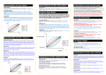
VTX10/10R PHYSICAL DIAGRAM RADIO CALIBRATION CON’T Capacitor board must be soldered properly as indicated below. 4. Pull full throttle for one second. (Followed by beep tone, N/R LED Each solder post has is labeled to indicate motor signals (A/B/C) and power connectors (+/-). Do not apply high heat on the solder posts for more than 10 seconds to avoid damage on the VTX ESC. 5. Push full brake then release. (Followed by beep tone, will be indicated as the image shown at right.) all LED’s will cycle.) 6. Calibration completed! SENSORED BRUSHLESS ESC INTRODUCTION The VIPER VTX Series sensored Electronic Speed Controller is the ultimate in engineering design from Viper R/C Solutions, Inc. Our commitment to quality and exhaustive track testing ensure that VTX series sensored Electronic Speed Controllers give you the smoothest power band and reliable performance in the most demanding R/C conditions. Please read the following instructions carefully before installing your new VTX system. SETTING UP VTX ESC ON ProGauge V-PORT LED INDICATORS S = Race Stock / Blinking Mode (Green LED will be blinking when in Race Stock/Blinking Mode) Do not test the motor without loading. This means without a pinion gear on the motor and running the motor at full power. F = Forward (Solid red LED at full throttle) Do not connect reversed voltage. This will damage the ESC and battery. R = Reverse/Brake POWER ON/OFF VTX ESC Do not leave batteries plugged into the ESC when not in use to prevent short circuits and over discharging the battery. Power On = Press the red button on the V-PORT. Always monitor both the ESC and motor temperature after running them. Temperature should never exceed 160 degrees Fahrenheit. VTX series ESC features a high performance switching BEC. It requires high quality radio system. 2.4GHz and high quality FM radio systems are the most suitable to work with VTX system. AM radio system will cause noise that results poor performance and operation failure of the VTX System. ON Resistance Max Input Voltage Support Li-Po Cell Max Peak BEC voltage/ amp Motor Limit Dimensions (WxLxH) Weight VTX10R 0.000225Ω * 2 17V / 4S Li-Po 2S~4S 7V / 5A 7V / 5A 540 / 6.5T 30x32.5x14.5mm 47g 550 / no limit 30x32.5x19.5mm 66g 3. F/R LED will light up to indicate that the VTX is in PROGRAMMING MODE. (LED indicator shown as image below) 4. Connect the ProGauge to the V-PORT by with V-PORT link cable (included), and then scroll down to “Link Device” on the ProGauge menu. Use the ESC/Up/Down/OK keys on the ProGauge to Change/Load/Save settings. Please refer to Table.1 for setting option and parameters. 5. Any setting changed on ProGauge needs to be saved in order to store in the VTX system memory. 6. After saving the settings, unplug the V-PORT connector and press the red power button for one second to go back to RUNNING MODE. (Solid orange LED at full brake/reverse) Pay attention to the motor and ESC timing. More timing will generate more heat on both the ESC and the motor. VTX10 0.00045Ω * 2 17V/ 4S Li-Po 2S~4S Press the red power button on the V-PORT for one second. N = Neutral (Green LED) VTX10/10R SPECIFICATIONS Power on VTX ESC. (Transmitter could be on or off.) 2. P = Power On (Red LED) PRECAUTIONS 1. Power Off = Press and hold the red button on the V-PORT for three seconds. All LED’s will light up and turn off individually. RADIO CALIBRATION Every VIPER VTX ESC needs to run radio calibration process when it is brand new out of the package, switching radio system, or after firmware update. Process is as easy as the following steps after all wires and battery connector are properly soldered. Connect a proper/charged battery pack to the ESC. Turn on the transmitter with the throttle endpoint adjustments at 100% and all throttle trims centered. Press and hold the red power button V-PORT LED indicator shows in PROGRAMMING MODE. V-PORT LED indicator shows in RACE STOCK / BLINKING MODE. V-PORT LED indicator shows in RACE MODIFIED MODE. on the V-PORT for three seconds. (Followed by beep tone, F/N LED on the V-PORT will be indicated as the image shown at right) VTX series user manual A03 20110412 PROGRAMMING OPTION: BRAKE PROGRAMMING OPTION: DRAG BRAKE Brake Strength: Parameters from 0% (Disabled) to 100%, (1% incremental). A lower Brake Strength percentage will have less push brakes, while a higher percentage will have stronger push brakes. Brake PWM Frequency: Parameters are 2000Hz / 2500Hz / 3200Hz / 4000Hz / 8000Hz / 12000Hz / 16000Hz PWM stands for Pulse Width Modulation and is rated in Hertz, meaning cycles per second. A lower frequency will have a more aggressive braking feel. A higher frequency results in smoother braking, is more precise, and increases the ESC temperature. Brake Curve: Parameters are +EXP1 to +EXP5 / Linear / -EXP1 to -EXP5. A negative EXP Brake Curve will have a softer brake feel at the beginning of the brakes being engaged and get more aggressive as the brake are fully engaged. A linear Brake Curve will be uniform throughout the whole brake range. A positive EXP Brake Curve has strong brakes initially and then becomes softer. Brake Strength +EXP5 +EXP1 Linear -EXP1 -EXP5 Motor RPM Neutral Brake: Parameters from 0% (Disabled) to 100%, 1% Incremental. This is how much brake is applied at neutral throttle. Neutral brake is still functional regardless if Dynamic Brake is enabled or not. DYNAMIC DRAG BRAKE Dynamic Drag Brake is an advanced function under the option of Drag Brake. It offers another step of drag brake at higher RPM of your choice. It is with 3 parameters. Trigger RPM sets the motor RPM where you wish the Dynamic Drag Brake to trigger. Max Brake Strength sets the brake strength level when Dynamic Drag Brake kicks in. Dynamic Curve sets the brake curve from Max Brake Strength to Neutral Brake point. Max Brake Strength: Parameters from 0% (Disabled) to 100%, (1% incremental). This is how much brake is applied at the top of the Dynamic Brake Curve, after the Activate RPM is reached. Dynamic Curve: Parameters are +EXP1 to +EXP5 / Linear / -EXP1 to 1EXP5. This is engaged after the Neutral Brake percentage is reached. A negative EXP Dynamic Brake Curve will have a softer brake feel at the beginning of the brakes being engaged and get more aggressive as they are fully engaged. A linear Dynamic Brake Curve will be uniform throughout the whole brake range. A positive EXP Dynamic Brake Curve has strong brakes initially and then becomes softer. Trigger RPM: Parameters from 500RPM to 60000RPM, (500RPM incremental). The motor RPM that engages the Max Brake Strength. Brake Max Brake Strength PROGRAMMING OPTION: THROTTLE Throttle PWM Frequency: +EXP5 Parameters are 2000Hz / 2500Hz / 3200Hz / 4000Hz / 8000Hz / 12000Hz / 16000Hz PWM stands for Pulse Width Modulation and is rated in Hertz, meaning cycles per second. A lower frequency will have a more aggressive throttle feel and have less motor RPM. A higher frequency results in smoother throttle, is more precise, produces more motor RPM, and increases the ESC temperature. Throttle Punch: Parameters from 1% to 100%, (1% incremental). A lower Throttle Punch percentage will have a slower throttle response and feel softer initially. A higher Throttle Punch percentage will have a faster throttle response. Throttle Curve: Parameters are +EXP1 to +EXP5 / Linear / -EXP1 to -EXP5. A lower Throttle Curve EXP will have a softer throttle feel at the beginning of the throttle power band and get more aggressive as it is fully engaged. A linear Throttle Curve will be uniform throughout the whole throttle range. A higher Throttle Curve EXP has strong throttle initially and then becomes softer. Dead Band: Parameters are Off/Narrow/Middle/Wide. This is the amount of “play” when the throttle is engaged. Off makes the throttle engage more instantaneously, while Wide would have a lag. +EXP1 Linear -EXP1 -EXP5 Neutral Brake Linear -EXP1 -EXP5 Throttle Position Start RPM: Parameters from 500 to 30000 RPM (500 RPM incremental). This sets the start RPM that acceleration timing engages. This parameter should be based on the motor KV and the track condition. To calculate Start RPM: Start RPM = Motor KV x 6.4 x 0.3 For example, if the motor KV is 2000, it will be 2000x6.4x0.3 = 3840. Then you set the START RPM = 3500 to 4000 Set Up Tips: Lower start RPM does not mean to have more power at lower end. The motor needs to have enough RPM before the acceleration timing could kick in efficiently. Try to start the parameter at higher side and monitor the motor temperature before making next adjustment. Finish RPM: Parameters from 500 to 50000 RPM (500 RPM incremental). This sets the start RPM that acceleration timing finishes. To calculate the Finish RPM: FINISH RPM = Motor KV x 6.4 For example, if the motor KV is 2000, it will be 2000x6.4 = 12800. Then you set the finish RPM = 12000 to 13000 Max Advanced Timing: Parameters from 0 to 40 degrees (1 degree incremental). This sets the maximum advanced timing at the time the motor reaches the set Finish RPM. TOP SPEED TIMING Slew Rate: Parameters from 1 to 50 degrees/1000RPM (1 degree incremental). This sets how fast the ESC reaches the maximum advanced top speed timing. The larger number will have more aggressive top speed acceleration while the smaller number will have smoother feel. Max Advanced Timing: Parameters from 0 to 40 degrees. This sets the maximum advanced timing at the time the motor reaches top speed range. PROGRAMING OPTION: MISC CONTROL Run Mode: PROGRAMING OPTION: PROTECTION Battery Cut Off: Parameters from 4.5V to 13.5V, 0.1V Incremental. Allows user to set the cut-off for the appropriate voltage per type of battery used. ESC Temperature Cut Off: +EXP1 ACCELERATION BOOST RPM Parameters from 160 Degrees to 270 Degrees (10 degrees incremental). Motor temperature cut activation is indicated by blinking “F” and “R” LEDs. +EXP5 VIPER VTX series ESC offers advanced timing system for extreme racing competitions. The MOTOR POWER has 2 sections with 5 parameters. It allows you to set up and enhance acceleration and top speed performance. Tips: Always start testing the MOTOR TIMING with minimum advanced timing. Most sensored brushless motors have 30 degrees physical advanced timing with adjustable end bell for more or less timing. The total advanced timing (motor + ESC) should not be over 60 degrees for optimized performance and efficiency. Warning: MOTOR TIMING option generates a lot of power and will easily overheat and moreover to damage both ESC and motor. VIPER R/C SOLUTIONS will not be responsible for any equipment damage caused by MOTOR POWER settings. Trigger RPM Motor Temperature Cut Off: Throttle Punch PROGRAMMING OPTION: MOTOR POWER Parameters from 160 Degrees to 270 Degrees (10 degrees incremental). ESC temperature cut activation is indicated by blinking “F” and “R” LEDs with solid “N” LED. Parameters are Practice/Race Stock/Race Modified. Practice allows all settings to be adjusted on the ESC. Also, it allows reverse. Race Stock locks out reverse and does not allow any Motor Timing to be adjusted. Race Modified locks out reverse while maintaining Motor Timing adjustability. SBEC Voltage: Parameters from 5.0V to 7.0V (0.1V incremental). A higher voltage will make servos react faster at the expense of a shorter life span. However, do not set SBEC Voltage above the servo manufacturer’s recommended voltage. Forward Power: Parameters from 50% to 100%(1% incremental). This setting allows you to limit the forward power. Reverse Power: Parameters from 25% to 100%(1% incremental). This setting allows you to limit the reverse power. Auto Power Off: Parameters from 1 to 10 minutes(1 minute incremental). This allows the user to set the ESC to power off if it remains in neutral for the amount of minutes set. CHANGE PROFILE WITHOUT A ProGauge UTILIZE FACTORY PRE-LOAD PROFILES 1. Connect a proper/charged battery pack to the ESC. 2. Power on transmitter. 3. Press and hold the red power button on the V-PORT for three seconds. (Followed by beep tone, F/N LEDs on the V-PORT will be indicated as the image shown at right) 4. Press the corresponding number of time of the desired profile (refer to TABLE.1 below) on the red power button on the V-PORT. For example, press 5 times if you wish to load profile 5. The F/R LEDs will be indicated on every button press. 5. Release the power button for 3 seconds. The VTX ESC will save the profile number and F/R LEDs will be flashing the number of time of the corresponding profile that it was saved. 6. The VTX ESC will then run an auto system reset. The F/R LEDs will flash the corresponding profile number every time after beeping of system initialization. VIPER VTX series ESC was designed with 8 profiles space for storing settings for different tracks/ applications, and for easy /quick changes. We have spent countless track hours to test VTX series ESC and designed 8 factory pre-loaded profiles for drivers who need easier and quicker start of using VIPER VTX ESC without a ProGauge. For drivers who use VIPER VTX-LITE version without a ProGauge, this will allow a quick way to switch to the most suitable profile to start using VTX ESC in just a few minutes. TABLE.1 VIPER VTX10/10R FACTORY PRE-LOAD PROFILES Brake Profile # Application 1 2 3 4 5 6 7 8 SPEC off road no-boost MOD off road no-boost SPEC off road 13.5T boost SPEC off road 17.5T boost SPEC on road no-boost MOD on road no-boost SPEC on road boost PRACTICE no-boost Intended Motors Drag Brake Strength Curve Neutral Brake 100% 100% 100% 100% 100% 80% 100% 100% Linear Linear Linear Linear Linear Linear Linear Linear 10% 10% 10% 10% 10% 12% 10% 10% 13.5T to 21.5T 6.5T to 10.5T 13.5T 17.5T 13.5T to 21.5T 2.5T to 10.5T 13.5T to 21.5T All Turns Dynamic Brake Trigger RPM Max Brake Strength Disable Disable 12000RPM 5% 11000RPM 5% 10000RPM 5% Disable Disable 14000RPM 7% 10000RPM 5% Disable Disable Throttle Motor Power MISC Control Curve Punch Curve Acceleration Boost Top Speed Timing SBEC Voltage Reserve Power Disable Linear Linear Linear Disable Linear Linear Disable 100% 70% 100% 100% 100% 60% 100% 100% Linear Linear Linear Linear Linear Linear Linear Linear Disable Disable 30 30 Disable Disable 30 Disable Disable Disable 20 20 Disable Disable 30 Disable 6.0V 6.0V 6.0V 6.0V 6.0V 6.0V 6.0V 6.0V Disable Disable Disable Disable Disable Disable Disable 50% Protection Battery ESC Temp Cutoff Cut 6.4V 6.4V 6.4V 6.4V 6.4V 6.4V 6.4V 6.4V 220 F 220 F 220 F 220 F 220 F 220 F 220 F 220 F TABLE.2 VIPER VTX10/10R PROGRAMMING PARAMETERS Root Manu Menu/Options Brake Drag Brake Throttle Change Setting Menu Brake Strength Brake PWM Frequency Brake Curve Neutral Brake Dynamic Brake Throttle PWM Frequency Throttle Punch Throttle Curve Dead Band Acceleration Boost Motor Power Top Speed Timing Misc Control Protection Load Setting Save Setting Run Mode Hole Shot Launch SBEC Voltage Forward Power Reverse Power Auto Power Off Battery Cut Off Motor Temperature Cut ESC Temperature Cut Menu/Option Parameters 0% (disable) to 100% (1% incremental) 2000Hz/2500Hz/3200Hz/4000Hz/5000Hz/6400Hz/8000Hz/9600Hz/12000Hz/160000Hz EXP1 to EXP5 / Linear / -EXP1 to -EXP5 0% (disable) to 100% (1% incremental) Max Brake Strength Dynamic Curve Trigger RPM 2000Hz/2500Hz/3200Hz/4000Hz/5000Hz/6400Hz/8000Hz/9600Hz/12000Hz/160000Hz 1% to 100% (1% incremental) EXP1 to EXP5 / Linear / -EXP1 to -EXP5 off/Narrow/Middle/Wide Start RPM Finish RPM Max Advanced Timing Slew Rate Max Advanced Timing Practice/Race Stock/Race Modified Disable/1 to 5 second (1 second incremental) 5.0V to 7.0V (0.1V incremental) 50% to 100% (1% incremental) 25% to 100% (1% incremental) Disable, 1 to 10 Minutes (1 minute incremental) 4.5V to 13.5V (0.1V incremental) Disable, 160 degrees to 270 degrees (10 degrees incremental) Disable, 160 degrees to 270 degrees (10 degrees incremental) Option Parameters 0% (disable) to 100% (1% incremental) EXP1 to EXP5 / Linear / -EXP1 to -EXP5 Disable, 500RPM to 60000RPM, 500RPM incremental PRODUCT WARRANTY Your VIPER VTX series sensored ESC is guaranteed to be free from defects in materials and workmanship for a period of 365 days. Your original receipt showing the item and the date and place of purchase is required with your warranty service application. An ESC that is found to have been mishandled, abused or used incorrectly, including use in an application other than that for which the ESC is intended, will not be covered under the warranty. Viper R/C Solutions, Inc. has no control over the use of the ESC application with other electronic devices such as motors and batteries. Viper R/C Solutions, Inc. is not liable for any loss or damage, whether direct or indirect, incidental, or consequential, or any situation from the use, misuse or abuse of the product. Your VTX series sensored ESC is not a toy. This product is not intended for use by a child under age of 14 without adult supervision. The VTX ESC generates a lot of power that could result physical injuries. By setting up, connecting or operating the product, the user accepts all related liabilities. SERVICE & SUPPORT 500 to 30000 RPM (500 RPM incremental) 500 to 50000 RPM (500 RPM incremental) 0 to 40 Degrees (1 degree incremental) 1 to 50 degrees/1000RPM (1 degree/1000RPM incremental) 0 to 40 Degrees (1 degree incremental) 1. All requests for warranty service require the original proof of purchase showing the item, date, price, and dealer info. 2. For service, please visit www.viper -rc.com and follow the service instructions for the quickest turnaround time. Or call us at 1-866-2068558. 3. For all technical questions, please visit www.viper-rc.com for the corresponding FAQ, or e-mail your question to [email protected] . Profile 1 to 8 Profile 1 to 8 VTX series user manual A03 20110412