1
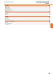
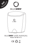
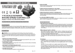
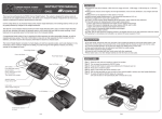
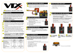
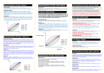
INSTRUCTION MANUAL
For 1/12 Onroad Competition
Support Both Sensor or Sensor-less Brushless Motor
INTRODUCTION
Thank you for purchasing Gforce 1S 120A ESC from G-FORCE, INC.
Please read the Instruction Manual thoroughly before you use the product. These operating
instructions are designed to ensure that you quickly become familiar with its features and
functions and make full use of this product.
FEATURES
Users could set the turbo and boosting timing which can improve the motor RPM to get
its best performance.
Well-performed throttle and brake control function could control the punch/brake rate by
point and the point can be set by user. The precision of the punch/brake rate is 1. And
the user could also custom the throttle/brake curve.
Punch control is reasonable and precise and can meet different customers' request for
linear and power.
Red copper connector is used internal of the ESC. It can decrease the internal
resistance at high current situation.
The circuit is managed by intelligent thermal management kernel algorithm which can
improve driving skill. The dynamic loss can be reduced effectively when the motor is
running at high speed or the user changes the motor speed frequently so that the motor
can be more stable when running.
The internal resistance can be reduced by laminated copper stack control technology so
that the dynamic thermal equilibrium can be got. In this case, the aluminum heat sinks
can works effectively.
The electronic switch is built in so that it could save space. And the electronic switch is
more sensitive and reliable.
The users could set and store 10 sets of profiles in the ESC. These data could be called
out at any time without any special program setting. All the setting can be exported or
imported so that the user could compare and analyze.
Safety features: low voltage protection, motor and ESC overheat protection and signal
lost protection.
SAFETY NOTE
It is not a toy and suitable for users older than 14 years old.
Never allow water, moisture, oil or other foreign materials to get inside ESC, motor, or on
the PC Boards. It may damage the ESC completely.
Never disassemble the ESC and modify the components on the PC Boards.
Suggest using the original wires and connectors which are packed in the box.
Never solder one part for more than 5 seconds as some components will get damaged
by high temperature.
Never run the ESC w/o load at full throttle and it may damage the bearings and other
moving parts.
Please make sure the location where to fix the ESC has good airflow ventilating so that
the heat could dissipate quickly.
To avoid short circuit, please keep the ESC connectors far away from other metal parts.
Never connect the battery in polarity in reverse.
Please remove the pinion gear before performing calibration and programming functions
with this system. Please keep your hands, hair, cloth, clear from the gear train and
wheels.
Before you switch on the ESC, please make sure all the cables are well solder with the
connectors (It is easy to get loose when running) . What's more, make sure the cables
not touch the moving parts.
Electronic motor timing will increase the temperatures of ESC and brushless motor. Use
extreme caution when setting up and testing your application to avoid overloading and
overheating.
Incorrect Boost and Turbo timing setting may cause permanent damage to the ESC and
motors. Please choose proper ratio and timing setting according to motor's instruction.
To avoid signal interference, please always turn on the transmitter first THEN turn on the
speed control. Do the opposite when powering it off.
Never use faulty accessories, e.g. motor which may damage the ESC. Always insulate
exposed wiring with heat shrink tubing or electrical tape to prevent short circuits, which
can damage ESC too.
Always disconnect the battery pack from the speed control when not in use to avoid
short circuits and possible fire hazard. When the ESC is switched off, there is still small
current and it may cause over discharge of the battery after some time.
The ESC can support 1 cell LiPo battery only.
ESC CALIBRATION
1) Plan Speed Control Placement
Choose a location for the speed control that is protected from debris. To prevent radio
interference, place the speed control as far away from the radio receiver as possible and
keep the power wires as short as possible. Select a location that has good airflow
ventilating. If the ESC gets air flow, it will run cooler; and that means it will be more
efficient.
2) Mount Speed Control in Vehicle
Use double-sided tape to mount the speed control in vehicle (do not use CA glue).
3) Soldering
Cut the ESC's BLUE, YELLOW & ORANGE silicone motor power wires to the desired
length and strip about 3.2mm-6.35mm (1/8”-1/4”) of insulation from the end of each wire.
“Pre-tin”the wire by heating the end and applying solder until it is thoroughly covered.
CAUTION: By very careful not to splash yourself with hot solder.
Place the ESC's BLUE Phase ‘A’ motor wire onto motor's ‘A’ solder tab and solder. Use
soldering iron to apply heat to exposed wire; begin adding solder to tip of soldering iron
and wire. Add just enough solder to form a clean and continuous joint from the plated
area of the solder tab up onto the wire. Solder the ESC's YELLOW Phase‘B’ motor wire
to the motor's ‘B' solder tab and Solder the ESC's ORANGE Phase ‘C' motor wire to
motor’s ‘C’ solder tab.
CONNECTION
1) Connect the motor sensor harness to ESC. Insert the 6 pin connector on the end of the
motor's sensor wires into ESC's sensor harness socket.
2) Connect Throttle lead to ESC and other end to the Receiver (Throttle Channel, Ch2)
3) Solder the motor and the ESC.
4) Connect ESC to battery pack.
Black power wire
Red power wire
(battery positive)
(battery negative)
Throttle
lead
Receiver
Note: We will not be responsible for any damage caused by non-compliance with above
instruction.
Battery
Pack
Calibration is necessary for the first use of the ESC, or whenever used with a new/different
transmitter. Individual transmitter's signals for full throttle, full brake and neutral vary. You
must calibrate your ESC so that it will operate more effectively with your transmitter.
How to calibrate the ESC?
ESC switch OFF.
Connect the ESC to the battery and the motor.
Turn on the transmitter.
Press and hold the ESC switch for few seconds, the motor will ring long beep once. After
that, the red LED will blink the motor will ring like beep-beep-beep… in a row which indicates
it is time to set the neutral position, full throttle and full brake one by one. You could release
the ESC switch now.
Keep the throttle trigger in neutral position, press the ESC switch once, the
green LED will blink once then extinguish and the motor will ring beep once
which indicates the neutral position has been set.
Hold full throttle and press the ESC switch once, the green LED will blink
twice then extinguish and the motor will ring twice like beep-beep which
indicates the full throttle has been set.
Move the throttle trigger to full brake and hold full brake, press the ESC
switch once, the green LED will blink three times then extinguish and the
motor will ring three times like beep-beep-beep which indicates the full brake
has been set.
After the calibration is finished, keep the throttle in neutral position, the red
LED will stay ON, the ESC and the motor is ready to work.
ESC ON/OFF AND LED INDICATOR
1. ESC ON/OFF: When the ESC is OFF, press the switch once, the motor will ring beep once and
the red LED will stay on (Motor boost and turbo timing is on), then the ESC is ready to work.
When the ESC is on, press the switch once, the LED will extinguish and the ESC is OFF.
Note 1: After running at full load, the ESC will be very hot. In this case, please turn off the
ESC after it cools down.
Note 2: When the motor is running, the ESC can't be powered off by pressing the switch;
when the motor stops working, the ESC can be powered off. In an emergency,
please disconnect the battery to power off the ESC.
Note 3: When the motor is running, keep the trigger of the transmitter to full brake for 8
seconds, the ESC will be off.
Power
Switch
2. Explanation of LED Indicator
Bluetooth Module
(Optional part)
The firmware can be updated by connecting the ESC with PC.
It can be off by keeping the trigger to full brake for 8 seconds when running.
1/8
PREPARATION
Yellow motor
phase wires
(phaseB)
Motor
Sensor Wire
2/8
Blue motor
phase wires
(phaseA)
3/8
Orange motor
phase wires
(phaseC)
The throttle trigger is in neutral position
Red LED is blinking (zero timing)
The throttle trigger is in neutral position
Red LED stays on
(Motor boost and turbo timing is on)
The motor is running while the throttle trigger doesn’t
reach to the highest throttle/brake position
Green LED is blinking.
The throttle trigger is at the highest throttle/brake position.
Green LED stays ON
4/8
ESC PROGRAMMING
Programmable Items and Description
The ESC can be programmed by program box or PC(connecting by program box).
Section
How to program the ESC?
Red power wire
(battery positive)
General
Setting
Battery
Pack
Throttle
Control
Black power wire
(battery negative)
Power
Switch
Brake
Control
OR
To PC
Boost
Timing
Turbo
Timing
Program Item
Running Mode
Motor Direction
Reverse Speed
Voltage Cutoff
ESC Overheat Protection
Motor Overheat Protection
Punch Rate Switch Point
1st Stage Punch Rate
2nd Stage Punch Rate
TH Input Curve
Throttle Dead Band
Throttle Status
Drag Brake
Brake Strength
Initial Brake
Brake Rate Switch Point
1st Stage Brake Rate
2nd Stage Brake Rate
Brake Input Curve
Boost Timing
Boost Start RPM
Boost End RPM
Boost Liner Slop
Boost Constrain by TH
Turbo Timing
Turbo Activation Method
Turbo Full TH Delay
Turbo Start RPM
Turbo Engage Slop
Turbo Deactive Slop
Profiles Preset
Description
Forward/Brake Forward/Brake/Reverse
Forward/Reverse
Normal
Reverse
25-100% (in 1% increment)
3.0-11V (in 0.1V increment), disable Auto (3.2V)
85℃/185℉ 105℃/221℉
85℃/185℉ 105℃/221℉
1-99%(in 1% increment)
1-30(in 1 increment)
1-30(in 1 increment)
Linear
Custom
0.002-0.150ms
125℃/257℉ Disable
125℃/257℉ Disable
The users could preset and store 10 sets of profiles in the ESC. These data could be called
out for application at any time without any special program setting. The user could also reset
the profile according to his request. There is one factory default setting called Modify in the
ESC. This mode can be used for modify class of touring car racing.
Setting Details of Modify Mode
Modify Mode Setting Value
Section
General
Setting
0-100%(in 1% increment)
0-100%(in 1% increment)
=Drag Brake 0-50%
1-99%(in 1% increment)
1-20(in 1 increment)
1-20(in 1 increment)
Linear
Custom
0-64 deg (in 1° increment)
1000-35000RPM (in 500RPM increment)
3000-60000RPM(in 500RPM increment)
Linear
Custom
Yes
No
0-64 deg (in 1° increment)
RPM
Full TH+RPM
Full TH
0.01-1.00S(in 0.01S increment)
Instant
9000-50000RPM/MIN(in 1000RPM increment)
1deg/0.1S - 64deg/0.1S (in 1° increment)
1-64 deg/0.1S(in 1°increment)
Instant
Throttle
Control
Brake
Control
Boost
Timing
If you set the cut-off voltage manually, please note the adjustable votage is TOTAL cut-off
voltage of the battery pack. In AUTO mode, the default cut-off voltage is 3.0V/S.
Note: The output power of the motor will be improved when you adjust the motor timing.
Electronic motor timing will increase the temperatures of ESC and brushless motor. Use
extreme caution when setting up and testing your application to avoid overloading and
overheating. Incorrect Boost and Turbo timing setting may cause permanent damage to the
ESC and motors. Please choose proper ratio and timing setting according to motor's
instruction.
Here is some suggestions about motor timing,
Motor Turns
Boost Timing
Turbo Timing
5/ 8
3.5T/4.0T
0
10
4.5T/5.5T
0
15
6.5T/7.5T
10
45
6/ 8
8.5T/9.5T
15
50
10.5T/11.5T
20
56
Turbo
Timing
Program Item
Running Mode
Motor Direction
Reverse Speed
Voltage Cutoff
ESC Overheat Protection
Motor Overheat Protection
Punch Rate Switch Point
1st Stage Punch Rate
2nd Stage Punch Rate
TH Input Curve
Throttle Dead Band
Throttle Status
Drag Brake
Brake Strength
Initial Brake
Brake Rate Switch Point
1st Stage Brake Rate
2nd Stage Brake Rate
Brake Input Curve
Boost Timing
Boost Start RPM
Boost End RPM
Boost Liner Slop
Boost Constrain by TH
Turbo Timing
Turbo Activation Method
Turbo Full TH Delay
Turbo Start RPM
Turbo Engage Slop
Turbo Deactive Slop
Description
Forward/Brake
Normal
25%
3.2V/1S (Auto)
105℃/221℉
SPECIFICATION
Constant/Burst Current
Motor Compatible
Car Compatible
Motor Limits
Resistance
0.0003ohm
Battery Cell Count
BEC Output
Size
Weight
120A/760A
Brushless Sensor & Sensorless Motor
1/12 onroad competition
3.5T(3 slots, 2 poles, 540 class motor)
1S LiPo
6V@3A, linear
38.5x37.8x22.5mm (LxWxH)
50g (w/o wire)
REMARK: All the testing results are working with 540 class motors with standard timing.
105℃/221℉
50%
5
15
Linear
0.080ms
10%
75%
=Drag Brake
50%
10
16
Linear
0°
15000RPM
25000RPM
Linear
Yes
10°
Full TH
0.10S
20000RPM
48°/0.1S
30°/0.1S
Products by
G-FORCE, Inc.
www.gforce-hobby.jp
Mare-kanda Bld.9F, 1-3-1, Kajicho, Chiyoda-ku,
Tokyo, 101-0044, Japan
≥13.5T
30
64
Copyright © 2014 G FORCE, Inc. All Right Reserved.
7/ 8
8/ 8