1
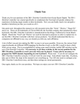
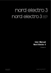
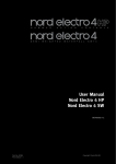
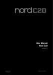
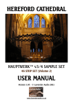
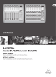
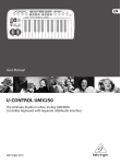
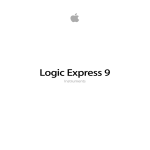
Drawbar Controller DB-1 User Manual Ocean Beach Digital www.oceanbeachdigital.com Program Button Power Button Battery Door Top Button DIP Switches Thank You Thank you for your purchase of the DB-1 Drawbar Controller from Ocean Beach Digital. The DB-1 Drawbar Controller was created specifically to complement the Nord and will greatly enhance the experience of playing organ sounds on these keyboards. Now you can finally reach over and grab a handful of drawbars just like you would on a B-3. A lot of effort was put into making the DB-1 as easy to set up as possible. However, the various Nord organ keyboards use different MIDI mappings for drawbar events, so the DB-1 needs to know which Nord you are using. This is accomplished by setting some small switches (called DIP switches) inside the battery compartment. It is necessary to set these switches in the correct position for the DB-1 Drawbar Controller to work correctly with your keyboard. It may also be necessary to program the MIDI channel, depending on your keyboard setup. Please note – if you do not configure the DB-1 Drawbar Controller correctly, it will not work for your setup. And nobody wants that. So please, take care to follow the steps in this manual to set everything up. You will only need to configure your DB-1 Drawbar Controller(s) once, and then these settings are stored permanently unless you change them later. One quick note: throughout this manual you will encounter terms like “Nord,” “Electro,” “Stage EX” and so on. These are all trademarks of Clavia DMI AB, the Swedish company that manufactures these keyboards. The DB-1 Drawbar Controller is manufactured in San Diego, California by Ocean Beach Digital. Words like “Nord” and “Electro” are used for descriptive purposes in order to explain how to use this DB-1 Drawbar Controller with their various products. You should understand that the two companies not affiliated in any way, nor should you infer any such affiliation. Once again, thank you for your purchase. We hope you enjoy your new DB-1 Drawbar Controller. Getting Started OK, you’re probably eager to get going with your new DB-1 Drawbar Controller, so we’ll try to make this as quick and painless as possible. Here are the five steps you need to follow: 1. Determine your keyboard & drawbar configuration 2. Set the DB-1 Drawbar Controller DIP Switch(es) accordingly 3. Make all your MIDI connections 4. Check for power 5. Teach your DB-1 Drawbar Controller(s) what MIDI channel(s) to use That’s it. So we will tackle each of these steps one at a time. 1 Step 1: Determining your keyboard and drawbar configuration Because you just bought this DB-1 Drawbar Controller, it’s probably safe to assume that you have a Nord keyboard that you want to connect it to. There are three “families” of Nord keyboards this Controller can talk to: The Electro family (Electro, Electro 2, Electro 3, Electro Rack) The Stage family (Stage, Stage EX, Stage 2) The organ family (C1, C2) and as luck would have it, these three families use different MIDI messages for drawbar commands. Also, you may be using one or two DB-1 Drawbar Controllers with your keyboard, and that affects how you set up your Drawbar Controllers. So the first step is to figure out what your configuration is. Are you using one DB-1 Drawbar Controller with an Electro? Are you using two Drawbar Controllers with a C1? That sort of thing. If you’re using two DB-1 Drawbar Controllers, you will need to designate one controller as the Upper manual drawbars, and the other one the Lower manual drawbars. Step 2: Setting the DIP Switches Inside the battery compartment of your DB-1 Drawbar Controller there’s a set of four small white switches called “DIP switches.” For each Drawbar Controller in your setup, you will need to put those switches in the correct position. Otherwise, your controller will send the wrong MIDI commands and all kinds of crazy things will happen. You don’t want that. The photos and descriptions that follow describe the switches as viewed from the rear of the Drawbar Controller, looking down into the battery compartment. So the MIDI jacks should be facing towards you and the front of the unit away from you. We are only concerned with the three left-most switches as viewed from the rear of the DB-1. Depending on when your DB-1 was manufactured, the DIP switches may be toggle / paddle style switches, or they may be sliding switches. Both styles are shown here. As you can see they are very similar, but use the one that most closely resembles the switches in your DB-1. All the DIP switch configurations are summarized on the next page. Note that the first group of three are the settings when you’re using a single DB-1 Drawbar Controller, and the second group of three are for when you’re using two of them. 2 one DB-1 controlling both Nord manuals Electro / Electro 2 / Electro 3 down-down-down MIDI channel is set automatically Stage / Stage EX / Stage 2 down-down-up MIDI channel(s) must be programmed in Learn mode C1 / C2 down-up-down MIDI channels must be programmed in Learn mode two DB-1's - one for upper and one for lower each manual for C1 / C2; upper for Electro / E2 / E3 down-up-up MIDI channel must be programmed in Learn mode lower manual for Electro / E2 / E3 up-down-down MIDI channel must be programmed in Learn mode Stage / Stage EX / Stage 2 up-down-up MIDI channel must be programmed in Learn mode GSi VB3 user defined via SYSEX up-up-up MIDI channel, polarity, and Control Change number are programmed via System Exclusive message 3 Step 3: Making all the MIDI connections: one DB-1 Drawbar Controller If you have one DB-1 Drawbar Controller, regardless of which Nord you have, your MIDI connections should look like this: optional external sound module midi in optional keyboard acting as lower organ manual c midi out d b a out in aux out in main in out midi The MIDI connections are as follows: a. DB-1 Drawbar Controller MAIN OUT to Nord MIDI IN b. DB-1 Drawbar Controller MAIN IN from Nord MIDI OUT c. DB-1 Drawbar Controller AUX OUT to external sound module (optional) d. DB-1 Drawbar Controller AUX IN from external keyboard triggering Nord (optional) 4 Step 3: Making all the MIDI connections: two DB-1 Drawbar Controllers If you have two DB-1 Drawbar Controllers, regardless of which Nord you have, your MIDI connections should look like this: optional external sound module midi in optional keyboard acting as lower organ manual midi out e f d c b a out in aux out in main out in aux in out midi upper drawbars a. b. c. e. f. g. out in main lower drawbars Upper Drawbar MAIN OUT to Nord MIDI IN Upper Drawbar MAIN IN from Nord MIDI OUT Upper Drawbar AUX OUT to Lower Drawbar MAIN IN Upper Drawbar AUX IN from Lower Drawbar MAIN OUT Lower Drawbar AUX OUT to external sound module (optional) Lower Drawbar AUX IN from external keyboard triggering Nord (optional) 5 Step 4: Check for Power The DB-1 was designed to run, when possible, using the voltage present on the MIDI signal coming in the MAIN MIDI IN jack. For this reason, if you plan to run off MIDI bus power, you need to make both MAIN MIDI IN and OUT connections as described above. That generally seems to work just fine for simple setups (ie nothing else connected via MIDI except your Nord and the DB-1.) If your setup involves the use of the AUX MIDI connections, it may be necessary to use a 9v battery. Power up your Nord, and double check the MIDI connections described above. The DB-1's power button operates differently from other power buttons you've encountered: button is in: DB-1 draws its power from the internal 9v battery (not included) button is out: DB-1 draws its power from the MIDI bus Whenever the DB-1 has power, the LED will flicker whenever you move a drawbar. If you don't see this, or if the DB-1 appears to be operating erratically, try installing a fresh 9v battery and putting the power button in the in position whenever the DB-1 is in use. When inserting the battery into the battery compartment, take care not to accidentally bump any of the DIP switches into different positions. And when whenever there’s no battery in place, you should use the protective battery terminal cover to prevent the battery harness contacts from inadvertently shorting against anything inside the drawbar controller. Some Words About MIDI Bus Power This DB-1 Drawbar Controller has been designed to run off MIDI bus power when possible. But you should understand that there is no MIDI Specification for drawing power off the MIDI bus. This is really unfortunate, as it’s quite handy for a small device such as this one. Ocean Beach Digital has gone to great lengths to minimize the current consumption of the DB-1 so that it can run under MIDI bus power in as many scenarios as possible. Most of our customers have found that a single drawbar module connected to a single keyboard works fine under MIDI bus power. But you may need to use a battery if you have a more complicated MIDI setup or if you are using multiple DB-1s. By the way – we also provided a way to make the power switch “off” position really truly off. That’s what the rightmost DIP switch is for. You'll probably never need to use it. When power switch is off, DB-1 draws power from MIDI bus When power switch is off, DB-1 cannot draw power from MIDI bus 6 Step 5: Setting the MIDI channel – one DB-1 Drawbar Controller This procedure varies slightly depending on your keyboard configuration, so please read carefully. Electro family with one DB-1 Drawbar Controller The short answer: MIDI channel selection happens automagically for Electro and Electro 2 setups, and also for Electro 3 setups that don't use an external keyboard as a lower organ manual. That seems to be the majority of DB-1 buyers. If you're among this group, you're done already. You can skip this step. The long answer: the DB-1 defaults to MIDI channel 1 at boot, but automatically switches to whatever channel you are using. This makes life very easy for most Electro owners. But if your Electro is on MIDI channel 6, you will need to play something before the DB-1 starts transmitting on channel 6. If that's an annoyance, you can set the MIDI channel explicitly. And if you're using an Electro 3 with a second keyboard as a lower organ manual, you will need to teach the DB-1 what MIDI channels you are using. The procedure is simple: 1. Press and hold the white PROGRAM BUTTON located on the rear panel. Hold this button down until the LED begins to flash. Release the button. The LED will continue to flash, indicating that you are in Learn Mode. 2. Press and hold the TOP BUTTON. While holding the TOP BUTTON, play a few notes on the Electro keyboard. If you have an Electro 3, and if you are using an external keyboard as a lower organ manual, play a few notes on that keyboard also. 3. Release the TOP BUTTON 4. Quickly press and release the PROGRAM BUTTON. The LED will stop flashing. You will only need to do this once. C1 or C2 with one DB-1 Drawbar Controller You need to teach the DB-1 Drawbar Controller which MIDI channels are used for the upper and lower manuals. To do this: 5. Press and hold the white PROGRAM BUTTON located on the rear panel. Hold this button down until the LED begins to flash. Release the button. The LED will continue to flash, indicating that you are in Learn Mode. 6. Press and hold the TOP BUTTON. While holding the TOP BUTTON, play a few notes on the upper manual, then play a few notes on the lower manual. 7. Release the TOP BUTTON 8. Quickly press and release the PROGRAM BUTTON. The LED will stop flashing. That’s it. The DB-1 Drawbar Controller now knows what MIDI channels you’re using. This information has also been written to FLASH memory, so you will not have to perform this step again unless you change your Nord’s MIDI channel assignments. 7 Stage / Stage EX / Stage 2 Stage 2 version 1.40 or later You should first verify that the Stage 2 is still using the default values in the MIDI Menu: Global MIDI Channel = 1 MIDI Slot A Channel = OFF MIDI Organ A Channel = OFF MIDI Piano A Channel = OFF MIDI Synth A Channel = OFF MIDI Slot B Channel = OFF MIDI Organ B Channel = OFF MIDI Piano B Channel = OFF MIDI Synth B Channel = OFF MIDI Prog Change Mode = Send & Receive MIDI Ctrl Change Mode = Send & Receive If you use an external keyboard as a lower organ manual, that keyboard cannot use the Stage's Global MIDI channel. You must pick some other MIDI channel. Set the external keyboard to transmit on this channel. In the Stage 2's MIDI Menu, also set the MIDI Dual KB Channel to this same channel. Lastly, put the Stage into Dual KB Mode. (This is all described in the Nord Stage 2 manual, by the way). To set the DB-1's MIDI Channel: 1. Press and hold the white PROGRAM BUTTON located on the rear panel. Hold this button down until the LED begins to flash. Release the button. The LED will continue to flash, indicating that you are in Learn Mode. 2. Press and hold the TOP BUTTON. While holding the TOP BUTTON, play a few notes on the Stage keyboard. If you have an external keyboard connected, do NOT play any notes on it. 3. Release the TOP BUTTON 4. Quickly press and release the PROGRAM BUTTON. The LED will stop flashing. If you set up a keyboard split, have two Slots active, and have organs active in both Slots, the two Slots act as independent organ manuals. The DB-1 drawbars will act upon the Slot that's in focus (the slot whose LED is flashing.) When using either a keyboard split or an external lower manual, change Slot focus between upper and lower organ manual by using the Slot A / Slot B buttons on the Stage 2 control panel. You can also program the Top Button to toggle Slot focus for you – see the section on programming the Top Button below. While in Learn Mode, press and hold the TOP BUTTON and press the Slot button that is currently not in Focus, forcing the Stage to change Slots. Then exit Learn Mode. 8 Stage, Stage EX, and Stage 2 prior to 1.40 What is now called a “Slot” on the Stage 2 used to be called a “Panel” on the Stage and Stage EX. This section will use the “Panel” nomenclature. In order for the DB-1 to control legacy Stage and Stage EX keyboards, it must make assumptions based on the MIDI channels it sees during the Learn Mode MIDI channel assignment. If it sees one MIDI channel, it will operate in single-channel mode. If the DB-1 sees two MIDI channels during the Learn mode assignment, it will assume that you have two organ manuals controlling two Panels. For this reason: If you do not use multiple organ manuals, before assigning the DB-1's MIDI channel, make sure that you only have Panel A active and that you have turned off all the Piano / Organ / Synth MIDI channel overrides in the MIDI menu, as shown in the Stage 2 section above. The DB-1 will keep track of whether it sees Note On events on one or two MIDI channels during the Learn process. To set the MIDI Channel: 1. Press and hold the white PROGRAM BUTTON located on the rear panel. Hold this button down until the LED begins to flash. Release the button. The LED will continue to flash, indicating that you are in Learn Mode. 2. Press and hold the TOP BUTTON. While holding the TOP BUTTON, play a few notes on the Stage keyboard. If you have an external keyboard connected or a split point set, play notes on the upper keyboard or split, then on the lower keyboard or split. 3. Release the TOP BUTTON 4. Quickly press and release the PROGRAM BUTTON. The LED will stop flashing. If the DB-1 sees one MIDI channel during this process, it will assume that you want to control one Panel, and the Top Button defaults to doing nothing, but can be reprogrammed as described later in the manual. If it sees two MIDI channels, it will remember both channels, and the Top Button will toggle between MIDI channels, allowing you to toggle control between both Panels. But keep in mind, on legacy Stage and Stage EX instruments, the DB-1 cannot control which Panel is in focus on the Stage control panel. That means the DB-1 could end up controlling the Panel that is not in focus. The drawbar commands will still be received by the Stage's “hidden” organ engine, but you won't see the LED bargraphs change on the control panel (because those bargraphs always represent the Panel in focus). Whew. Ok, you’re now ready to play. 9 Step 5: Setting the MIDI channel – two DB-1 Drawbar Controllers The procedure is the same for all keyboard configurations: You must teach each DB-1 Drawbar Controller separately what MIDI channel to use for its corresponding manual (upper and lower). We start with the Upper drawbar controller: 1. On the Upper DB-1 Drawbar Controller, press and hold the white PROGRAM BUTTON located on the rear panel. Hold this button down until the LED begins to flash. Release the button. The LED will continue to flash, indicating that you are in Learn Mode. 2. Press and hold the Upper DB-1 Drawbar Controller’s TOP BUTTON. While holding this button, play a few notes on the upper manual only. Release the button. 3. Quickly press and release the PROGRAM BUTTON on the Upper DB-1 Drawbar Controller. The LED will stop flashing. Now repeat the procedure for the Lower manual: 4. On the Lower DB-1 Drawbar Controller, press and hold the rear-panel PROGRAM BUTTON until the LED begins to flash. Release the button. The LED will continue to flash, indicating that you are in Learn Mode. 5. Press and hold the Lower DB-1 Drawbar Controller’s TOP BUTTON. While holding this button, play a few notes on the lower manual only. Release the button. 6. Quickly press and release the Lower DB-1 Drawbar Controller’s PROGRAM BUTTON. The LED will stop flashing. You have now taught each of the DB-1 Drawbar Controllers its MIDI channel. This information has been written to FLASH memory, so you will not have to perform this step again unless you change your Nord’s MIDI channel assignments. You will need to keep track of which DB-1 Drawbar Controller is upper and which is lower. You’ll get unexpected results if you later swap them without reprogramming them. Time to Play! That’s it! Go play some music. As you move each drawbar, you should see the LED display for the corresponding virtual drawbars move up and down. If not, carefully double-check the procedures in the five setup steps. Also, please note that that the Stage and the Electro only display one set of virtual bar-graph drawbars at a time, but these keyboards internally can support two organ manuals, each having their own drawbar registration. The DB-1 attempts to control the organ manual that is “in focus” on the control panel, and it attempts to keep track of panel focus changes by listening to the MIDI messages being sent by your Nord. There may be some exception cases where the Nord has silently changed panel focus undetected, and the DB-1 starts controlling the virtual drawbars that are not currently being displayed. These exception cases have been avoided where possible to do so. 10 Programming the TOP BUTTON The purpose of the TOP BUTTON depends on your keyboard configuration. Single DB-1 Drawbar Controller with C1/C2: the TOP BUTTON acts as a toggle which selects whether the drawbars are controlling the upper or lower organ manual. This button is not programmable, so you can skip to the next section. Single DB-1 Drawbar controller with Electro family, and Single DB-1 Drawbar Controller with Stage family and second keyboard set up as a lower organ manual: if you programmed two MIDI channels into your DB-1 Drawbar Controller, the TOP BUTTON will act as a toggle which selects which manual the drawbars are controlling, but it can be reprogrammed to do other things. For all other keyboard configurations, the TOP BUTTON does nothing initially but can be reprogrammed. The TOP BUTTON can be programmed to send most MIDI Control Change (CC) messages to the Nord. Subsequent pushes of the button will toggle between sending a data value of 0 and sending 127 (hex 7F) which is the maximum MIDI value. The TOP BUTTON is programmed by sending it a MIDI CC message while in learn mode while holding the TOP BUTTON down, similar to how MIDI channels are programmed. Many of the Nord’s front toggle panel functions work by sending either 0 or 127 for some MIDI CC, so you can program the TOP BUTTON to duplicate any of these functions. For example, you might want the TOP BUTTON to toggle the speed of the rotary simulator. Or on an Electro, if you use two manuals you might want the TOP BUTTON to toggle between Upper and Lower manual. To set this up: 1. Press and hold the white PROGRAM BUTTON located on the rear panel. Hold this button down until the LED begins to flash. Release the button. The LED will continue to flash, indicating that you are in Learn Mode. 2. Press and hold the TOP BUTTON. 3. While holding the TOP BUTTON , press the button on the Nord’s control panel whose function you would like to assign to the TOP BUTTON. 4. Release the TOP BUTTON 5. Quickly press and release the PROGRAM BUTTON. The LED will stop flashing. The TOP BUTTON has just “learned” the MIDI Control Change message associated with whatever Nord button you pushed. (This assumes that the Nord button you pushed causes a MIDI Control Change message to be send. Most of the Nord’s toggle-state buttons do this.) You should now be able to push the TOP BUTTON and see that it duplicates the function of the Nord button you just assigned to it. 11 Programming the TOP BUTTON (Continued) Send All Function: The TOP BUTTON can be programmed to resend all drawbar data whenever it's pressed. This is useful if you want to have the drawbars set to one registration and then bring up a patch set to some other registration. You can play the patch with the stored registration, and then instantly change the entire registration by pushing the Top Botton. The Top Button is programmed for Send All by exiting Learn Mode while holding the Top Button down. 12 Drawbar Auto-Sync An advantage of Clavia’s virtual drawbar system is the ability to have the virtual drawbars jump to a pre-programmed set of drawbar positions (organists call this a “registration”) whenever you select a preset. Now that you have real drawbars, when you call up this preset the virtual drawbars will jump to whatever registration was stored for that preset, but the physical drawbars of course will not. Imagine that you have all the drawbars in your DB-1 Drawbar Controller pushed in, and you call up a preset on your Nord that has an “888888888” registration where all of the drawbars are pulled out. The DB-1 Drawbar Controller normally does not generate any MIDI traffic unless you do something, the Nord’s control panel will not reflect the actual positions of your DB-1 drawbars. As you move each of the drawbars on your DB-1 Drawbar Controller, the Nord’s virtual drawbars will “snap” to the correct position, and when you’ve moved all of the drawbars the two will be back in sync. And some folks like that. And it's also possible to use the TOP BUTTON Send All function to resend everything at once, described earlier in the manual. A third option is Auto Sync. You can program the organ preset to resynchronize automatically with the DB-1 drawbar positions whenever the preset is selected, sorta like the B and Bb presets on an old console organ. The DB-1 can remember up to four MIDI Program Changes that you designate as Auto-Sync presets. These presets are stored by selecting Programs on your Nord while in Learn Mode and with the TOP BUTTON held down, so the procedure is very similar to how MIDI Channel and the TOP BUTTON are programmed: 1. Press and hold the white PROGRAM BUTTON located on the rear panel. Hold this button down 2. 3. 4. 5. until the LED begins to flash. Release the button. The LED will continue to flash, indicating that you are in Learn Mode. Press and hold the TOP BUTTON. While holding the TOP BUTTON , select the desired preset(s) using the Nord’s control panel Release the TOP BUTTON Quickly press and release the PROGRAM BUTTON. The LED will stop flashing. Note: if you are using two DB-1 Drawbar Controllers, you only need to perform this procedure on the Upper Manual Drawbar Controller. Now when you select the designated preset(s), all of the DB-1’s drawbar positions will be automatically re-sent to the Nord, effectively re-syncing the Nord with the positions of the physical drawbars on your DB-1 Drawbar Controller. If you are using a single DB-1 Drawbar Controller to control two organ manuals, the Upper manual will automatically be selected for you. 13 Learn Mode summary In earlier sections of this manual we have described various settings that can be stored using Learn Mode. Here’s a quick summary of all those settings. To enter Learn Mode: press and hold the white PROGRAM BUTTON located on the rear panel. Hold this button down until the LED begins to flash slowly. This should take approximately three seconds. Release the button. The LED will continue to flash slowly, indicating that you’re in Learn Mode. Once you’re in Learn Mode, the DB-1 Drawbar Controller listens for certain MIDI events and remembers them. The things that can be learned this way are: MIDI Channel (except for Electro with one DB-1 Drawbar Controller) TOP BUTTON function (except for C1/C2 with one DB-1; see “About the TOP BUTTON” above) Program Changes for Drawbar Auto-Sync The things learned in Learn Mode are written to FLASH memory. This memory is retained even when there’s no power, so you will only need to reprogram things in Learn Mode if your keyboard configuration changes, or if you decide to move your organ presets around. To exit Learn Mode: quickly press and release the small white PGM button on the rear panel. The LED will stop flashing slowly, and will resume flashing only when MIDI is sent or received. Clear Memory The things learned in Learn Mode can be un-learned by using the Clear Memory function, which restores everything to the factory defaults. To perform the Clear Memory function, press and hold the small white PROGRAM BUTTON on the rear panel. After about three seconds it will flash slowly, but continue to hold it down. After approximately 8 more seconds it will flash quickly. Release the button. All of the user setup data has now been cleared and the factory defaults have been restored. You will need to repeat Step 5 to reprogram the MIDI channel. Rubber Feet Your DB-1 Drawbar Controller comes with self-adhesive rubber feet. These feet are remarkably grippy and should help your drawbar controller stay parked where you want it. Peel four of the feet off of the rubber backing and apply them near the outside corners of the bottom of the drawbar controller enclosure. If you find that the 9 volt battery rattles inside the battery compartment, you can use one of the feet to stop that from happened. Just apply it to the bottom of the battery door and it’ll stop the battery from moving around. 14 Configuring the DB-1 with other MIDI tonewheel organs and modules The DB-1 was designed to be particularly easy to set up with Nord keyboards, but it can used with other keyboards, organ modules, and virtual organ software as well. However: Not all keyboards with drawbar organ sounds respond to drawbar commands. Many keyboards and modules just play an organ sample, with no ability to control the individual drawbar positions. So adding drawbars to such an instrument will not magically give it the power to make drawbar adjustments. There is no MIDI standard for drawbar events. Even among the various Nord models different MIDI CC values are used, which is why the DB-1 has DIP Switches to select specific Nord products. It’s unlikely that non-Nord keyboards will respond to Nord drawbar MIDI commands in a useful way. One exception to this is EVB3 which comes bundled with MainStage. In EVB3 parlance, keyboard mappings are called “MIDI Modes” and there is a MIDI Mode which emulates the Nord Electro mapping. Click on the MIDI Mode field and select NE. The DB-1’s DIP switches should be configured for Single DB-1 controlling Nord Electro. Another excellent and very popular virtual tonewheel system is GSi VB3. The DB-1’s default MIDI CC mapping in User-Defined mode is set to the VB3 defaults, with the TOP BUTTON preconfigured to toggle rotary speaker speed. Thus the DB-1 is compatible with VB3 right out of the box, with no programming necessary. Most virtual organ software can be trained to “learn” MIDI CC values and assign those commands to specific drawbars. That might be the easiest way to configure such a setup to work with the DB-1. But you can also configure the DB-1 directly. The DB-1’s drawbars and TOP BUTTON can be configured to send MIDI CC on any MIDI Channel. This programming can be performed using the DB-1 Configurator which can be downloaded for free on the Ocean Beach Digital website. 15 Internal MIDI Routing You may find this block diagram of the DB-1's internal MIDI routing useful. Note that it is the AUX MIDI IN that is merged with the DB-1s internal drawbars. in out MAIN AUX MIDI OUT MIDI IN MIDI OUT MIDI IN merge drawbars Ocean Beach Digital DB-1 You will probably want to connect your master controller’s output to the AUX MIDI IN jack, and the DB-1’s MAIN MIDI OUT to your sound module or virtual tonewheel software. This will allow you to use the DB-1’s internal MIDI Merger to merge your drawbar movements into the MIDI stream generated by your master controller keyboard. Note also that the DB-1 can only grab power from the MAIN MIDI IN jack, so you would need to use the 9v battery for power in this configuration. 16 Troubleshooting If you’re reading this section, apparently Trouble has befallen you and so must be shot. This section will guide you through the necessary steps. First, let’s take a step back and look at the big picture. The DB-1 works by sending MIDI messages to your Nord, and it also must be able to receive messages from the Nord for programming. If the setup steps at the beginning of this manual didn’t get things going for you, any one of several things could be the cause. In order for the DB-1 to function, the following conditions must all be met: The DB-1 must have enough power to operate. The Nord must receive the MIDI messages sent by the DB-1 The DB-1 must receive messages sent by the Nord. So let’s work our way down the list. 1. The DB-1 must have enough power to operate. The easiest way to remove any uncertainty is to connect a fresh 9-volt battery to the DB-1 and press the Power button in. When you move the DB-1 drawbars back and forth, you should see the LED flicker, indicating that the unit has power and that it’s sending MIDI messages. If this isn’t happening, make sure the Power button is on (pressed in) and that the battery is in good condition. Once you’ve verified the DB-1 has power, you can move on to the next step. 2. The Nord must receive the MIDI messages sent by the DB-1. Your Nord has a MIDI indicator LED of its own, and it should also flicker when you move the DB-1’s drawbars. If not, double check your cable connections – the DB-1’s MAIN OUT should be connected to the Nord’s MIDI IN, and the DB-1’s MAIN IN should be connected to the Nord’s MIDI OUT. You might also try swapping the cables for different ones to make sure it’s not a cable problem. 3. The DB-1 must receive messages sent by the Nord. Similarly, when you play note on the Nord, move the expression pedal, or press the virtual drawbar buttons, you should see the DB-1’s LED flicker, indicating that it is receiving those messages. If not, double check the cabling as described above. It might also be a Nord MIDI configuration issue, the resolution of which is described below. If it appears that you have physical connectivity (cables are plugged into the correct places), you should also verify that the Nord has been configured to send and receive MIDI Note On and CC information. All of the Nord models have MIDI menu functions to configure this stuff, and to our knowledge the default configurations work fine. But it’s possible at some point these menu settings have changed, so you’ll want to bust out your Nord’s manual and go to the MIDI menu sections towards the back of the manual. The things you want to look for are described on the next page. 17 Troubleshooting (continued) Here are the things to look for: For all keyboard models: make sure that you have the MIDI cables connected to the correct jacks. Even if you connect the cables backwards, the DB-1 may still be able to run off MIDI power, so don’t be fooled by this – make sure DB-1 MAIN OUT goes to Nord MIDI IN, and Nord MIDI OUT goes to DB1 MAIN IN. For Electro and Electro 2: make sure that the MIDI channel is set to 1-16, and not “—“ (off). For Electro 3: make sure the MIDI channel is set to 1-16, and not OF make sure Control Change (CC) Mode is set to Sr (Send and Receive). make sure Program Change Mode is set to Sr (Send and Receive). For Stage 2: double-check the MIDI menu settings described in the Stage 2 section of this manual For Stage and Stage EX: make sure the MIDI Panel A/B Channel is set to 1-16, and not Off make sure the MIDI Organ A/B Channel is set to 1-16, and not Off make sure MIDI Control Change Mode is set to Send & Receive make sure MIDI Prog Change Mode is set to Send & Receive 18 Troubleshooting (continued) For C1 Organ: make sure the Upper MIDI channel is set to 1-16. It should not be set to one of the “E” channels E1-E9 nor OFF. It has been reported that the C1 does not respond to CC messages (including drawbar commands) when using the “E” channels. similarly, make sure the Lower MIDI chanel is set to 1-16, but to a different channel than Upper make sure Continuous Controller Mode is set to Sr (Send and Receive). make sure Program Change Mode is set to Sr (Send and Receive). For C2 Organ: make sure the Swell Channel is set to 1-16, and not OFF make sure the Great Channel is set to a different channel than the Swell channel, and not OFF make sure Control Change (CC) Mode is set to Sr (Send and Receive). make sure Program Change Mode is set to Sr (Send and Receive). make sure the Local Control Mode is not set to E (external device). It has been reported that the C2 does not respond to to CC messages (including drawbar commands) in Local Mode E. in the System menu, make sure the Organ Trig Mode is set to n (normal). It has been reported that the C2 also does not respond to CC messages when in Fast Trigger Mode. 19 California Proposition 65 Warning This product contains chemicals known to the State of California to cause cancer and birth defects or other reproductive harm. Wash hands after handling. Disposal of Waste Equipment This symbol on the product or on its packaging indicates that this product must not be disposed of with your other household waste. Inappropriate disposal may be harmful. Instead, it is your responsibility to dispose of your waste equipment by handing it over to a designated collection point for the recycling of waste electrical and electronic equipment. The separate collection and recycling of your waste equipment at the time of disposal will help to conserve natural resources and ensure that it is recycled in a manner that protects human health and the environment. For more information about where you can drop off your waste equipment for recycling, please contact your local city office, your household waste disposal service or the shop where you purchased the product. Electromagnetic Compatibility Ocean Beach Digital declares that this product complies with the following standards regulating emissions and immunity: FCC Part 15 Class B EN550022 Class B EN55103-1 EN55103-2 ICES-003 Ocean Beach Digital declares under its sole responsibility that the Product Drawbar Controller DB-1 complies with Part 15 of FCC rules. Operation is subject to the following two conditions: (1) This device may not cause harmful interference, and (2) This device must accept any interference received, including interference that may cause undesired operation. 20 Warranty Information Ocean Beach Digital warrants this product, under normal use, to be free of defects in materials and workmanship for a period of one (1) year from date of purchase, so long as the product is owned by the original purchaser, with proof of purchase either from Ocean Beach Digital or from an authorized Ocean Beach Digital dealer. This warranty explicitly excludes cables which may become defective as a result of normal wear and tear. In the event that Ocean Beach Digital receives, from an original purchaser and within the warranty coverage period, written notice of defects in materials or workmanship, Ocean Beach Digital will either replace the product, repair the product, or refund the purchase price at its option. In the event that repair is required, a Return Materials Authorization (RMA) number must be obtained from Ocean Beach Digital. After this number is obtained, the unit should be shipped back to Ocean Beach Digital with the RMA number clearly written on the address label. Packages delivered without a valid RMA number will not be accepted and will be returned to the shipper. The package must also include a description of the problem and a copy of the original purchase receipt. Shipment to and from Ocean Beach Digital and possible nominal handling charges shall be the purchaser's responsibility. In the event that Ocean Beach Digital determines that the product requires repair because of user misuse or regular wear, it will assess a fair repair or replacement fee. The customer will have the option to pay this fee and have the unit repaired and returned, or not pay this fee and have the unit returned un-repaired. The remedy for breach of this limited warranty shall not include any other damages. Ocean Beach Digital will not be liable for consequential, special, indirect, or similar damages or claims including loss of profit or any other commercial damage, and in no event will Ocean Beach Digital's liability for any damages to the purchaser or any other person exceed the price paid for the product, regardless of any form of the claim. Ocean Beach Digital specifically disclaims all other warranties, expressed or implied. Specifically, Ocean Beach Digital makes no warranty that the product is fit for any particular purpose. This warranty shall be construed, interpreted, and governed by the laws of the state of California. If any provision of this warranty is found void, invalid or unenforceable, it will not affect the validity of the balance of the warranty, which shall remain valid and enforceable according to its terms. In the event any remedy hereunder is determined to have failed of its essential purpose, all limitations of liability and exclusion of damages set forth herein shall remain in full force and effect. 21 Ocean Beach Digital 4876 Santa Monica Ave #162 San Diego CA 92107 864-DRAWBARS (864-372-9227) www.oceanbeachdigital.com DB-1 Manual fw ver 2.00 rev a