1
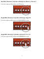
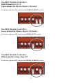
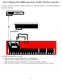
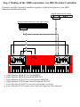
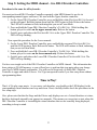
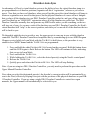
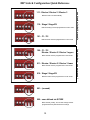
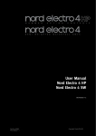
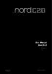
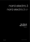
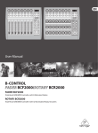
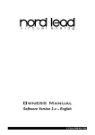
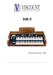
Thank You
Thank you for your purchase of the DB-1 Drawbar Controller from Ocean Beach Digital. The DB-1
Drawbar Controller was created specifically to complement the Nord and will greatly enhance the
experience of playing organ sounds on these keyboards. Now you can finally reach over and grab a
handful of drawbars just like you would on a B-3.
One quick note: throughout this manual you will encounter terms like “Nord,” “Electro,” “Stage EX”
and so on. These are all trademarks of Clavia DMI AB, the Swedish company that manufactures these
keyboards. The DB-1 Drawbar Controller is manufactured in San Diego, California by Ocean Beach
Digital. Words like “Nord” and “Electro” are used for descriptive purposes in order to explain how to
use this DB-1 Drawbar Controller with their various products. You should understand that the two
companies not affiliated in any way, nor should you infer any such affiliation.
A lot of effort was put into making the DB-1 as easy to set up as possible. However, the various Nord
organ keyboards use different MIDI mappings for drawbar events, so the DB-1 needs to know which
Nord you are using. This is accomplished by setting some small switches (called DIP switches) on the
rear of the Drawbar Controller. It is necessary to set these switches in the correct position for the
DB-1 Drawbar Controller to work correctly with your keyboard. It may also be necessary to
program the MIDI channel, depending on your keyboard. Please note – if you do not configure the
DB-1 Drawbar Controller correctly, it will not work for your setup. And nobody wants that. So please,
take care to follow the steps in this manual to set everything up. You will only need to configure your
DB-1 Drawbar Controller(s) once, and then these settings are stored permanently.
Once again, thank you for your purchase. We hope you enjoy your new DB-1 Drawbar Controller.
1
Getting Started
OK, you’re probably eager to get going with your new DB-1 Drawbar Controller, so we’ll try to make
this as quick and painless as possible. Here are the five steps you need to follow:
1.
2.
3.
4.
5.
Determine your keyboard & drawbar configuration
Set the DB-1 Drawbar Controller DIP Switch(es) accordingly
Make all your MIDI connections
Connect power to your Controller(s)
Teach your DB-1 Drawbar Controller(s) what MIDI channel(s) to use
That’s it. So we will tackle each of these steps one at a time.
Step 1: Determining your keyboard and drawbar configuration
Because you just bought this DB-1 Drawbar Controller, it’s probably safe to assume that you have a
Nord keyboard that you want to connect it to. There are three “families” of Nord keyboards this
Controller can talk to:
• The Electro family (Electro, Electro 2, Electro 3)
• The Stage family (Stage, Stage EX)
• The organ family (C1, C2)
and as luck would have it, these three families use different MIDI messages for drawbar commands.
Also, you may be using one or two DB-1 Drawbar Controllers with your keyboard, and that affects how
you set up your Drawbar Controllers.
So the first step is to figure out what your configuration is. Are you using one DB-1 Drawbar Controller
with an Electro? Are you using two Drawbar Controllers with a C1? That sort of thing. If you’re using
two DB-1 Drawbar Controllers, you will need to designate one controller as the Upper manual
drawbars, and the other one the Lower manual drawbars.
Step 2: Setting the DIP Switches
On the rear panel of your DB-1 Drawbar Controller there’s a rectangular window, and inside that
window is a set of small white switches called “DIP switches.” For each Drawbar Controller, you will
need to put those switches in the correct position. Otherwise, your controller will send the wrong MIDI
commands and all kinds of crazy things will happen. You don’t want that.
If you look very closely, you’ll see that there are some small numerals printed above each switch. The
numerals are upside down because the DIP Switch is attached to the bottom of the circuit board – don’t
be thrown by that. The photos and descriptions that follow describe the switches as viewed from the
rear of the Drawbar Controller, with the power connector to the immediate left and PROGRAM BUTTON
off to the right.
All the possible combinations are handled in the next two pages.
2
One DB-1 Drawbar Controller with Electro, Electro 2, Electro 3
Set the three right-most DIP switches in the UP position:
Single DB-1 Drawbar Controller with Stage, Stage EX
Set the three right-most DIP switches in the UP-UP-DOWN position:
Single DB-1 Drawbar Controller with Nord C1 or C2
Set the three right-most DIP switches in the UP-DOWN-UP position:
3
Two DB-1 Drawbar Controllers:
Both Manuals for C1, C2
Upper manual for Electro, Electro 2, Electro 3
Set the three right-most DIP switches in the UP-DOWN-DOWN position:
Two DB-1 Drawbar Controllers:
Lower manual for Electro, Electro 2, Electro 3
Set the three right-most DIP switches in the DOWN-UP-UP position:
Two DB-1 Drawbar Controllers:
Both manuals for Stage, Stage EX
Set the three right-most DIP switches in the DOWN-UP-DOWN position:
4
Step 3: Making all the MIDI connections: one DB-1 Drawbar Controller
If you have one DB-1 Drawbar Controller, regardless of which Nord you have, your MIDI connections
should look like this:
optional external sound module
midi in
optional keyboard acting as lower organ manual
c
midi out
d
b
a
out in
aux
out in
main
in out
midi
The MIDI connections are as follows:
a. DB-1 Drawbar Controller MAIN OUT to Nord MIDI IN
b. DB-1 Drawbar Controller MAIN IN from Nord MIDI OUT
c. DB-1 Drawbar Controller AUX OUT to external sound module (optional)
d. DB-1 Drawbar Controller AUX IN from external keyboard triggering Nord (optional)
5
Step 3: Making all the MIDI connections: two DB-1 Drawbar Controllers
If you have two DB-1 Drawbar Controllers, regardless of which Nord you have, your MIDI
connections should look like this:
optional external sound module
midi in
optional keyboard acting as lower organ manual
midi out
e
f
d
c
b
a
out in
aux
out in
main
out in
aux
in out
midi
upper drawbars
a.
b.
c.
e.
f.
g.
out in
main
lower drawbars
Upper Drawbar MAIN OUT to Nord MIDI IN
Upper Drawbar MAIN IN from Nord MIDI OUT
Upper Drawbar AUX OUT to Lower Drawbar MAIN IN
Upper Drawbar AUX IN from Lower Drawbar MAIN OUT
Lower Drawbar AUX OUT to external sound module (optional)
Lower Drawbar AUX IN from external keyboard triggering Nord (optional)
6
Step 4: Connect power to your DB-1 Drawbar Controllers
Your DB-1 Drawbar Controller was shipped with a “wall-wart” style power supply. You should
connect this power supply to your DB-1 Drawbar Controller(s) right now. Later on you can determine
whether you actually need it (more on that later) but for now, go ahead and connect to external power.
It will be one less variable to deal with if you encounter any issues.
Some Words About MIDI Bus Power
This DB-1 Drawbar Controller has been designed to run off MIDI bus power when possible. But you
should understand that there is no MIDI Specification for drawing power off the MIDI bus. This is
really unfortunate, as it’s quite handy for a small device such as this one, and it’s why we can make no
guarantees that your DB-1 will run under MIDI bus power in your keyboard configuration.
We strongly advise that when you first set up your DB-1 Drawbar Controller, you do so using the
supplied “wall wart” power supply. Once you determine that everything is working OK, then try
removing the external power supply and see what happens. Under most (but not all) keyboard
configurations, the DB-1 will work fine with no external power supply.
The MIDI spec was designed to avoid “ground loop” issues by electrically isolating the MIDI IN jack.
Unfortunately, if the MIDI IN jack is electrically isolated, there’s no way to draw power from it. So it’s
necessary to bend the rules a bit. We don’t foresee a reason why you’d need to do this, but the DB-1
does provides a way to preserve the specified electrical isolation of the MIDI IN jack by using the two
left-most DIP switches:
Drawbar module completely isolated
from MIDI bus, cannot draw power.
Must use external power transformer.
Drawbar module able to draw
power from MIDI bus.
7
Step 5: Setting the MIDI channel – one DB-1 Drawbar Controller
This procedure varies slightly depending on your keyboard configuration, so please read carefully.
Electro family with one DB-1 Drawbar Controller: this step is not necessary. Your DB-1’s MIDI
channel selection happens automagically, so you’re all ready to go!
Stage / Stage EX with one DB-1 Drawbar Controller: you need to teach the DB-1 Drawbar
Controller which MIDI channel(s) you are using in your setup. To do this:
1. Press and hold the white PROGRAM BUTTON located on the rear panel. Hold this button down
until the LED begins to flash. Release the button. The LED will continue to flash, indicating
that you are in Learn Mode.
2. Press and hold the TOP BUTTON. While holding the TOP BUTTON, play a few notes on the
upper manual.
3. If you have a second keyboard connected as a lower organ manual, while still holding the TOP
BUTTON play a few notes on that keyboard.
4. Release the TOP BUTTON
5. Quickly press and release the PROGRAM BUTTON. The LED will stop flashing.
Additional steps for Stage: In your Stage’s MIDI menu, you need to change the following settings:
• MIDI Organ A/B Channel: the default is off but needs to be set to a channel (1 to 16)
• MIDI Prog Change Mode: needs to be set to either Receive or Send and Receive in order to
use the Drawbar Auto-Sync feature
• MIDI Ctrl Change Mode: needs to be set to Send & Receive to program the TOP BUTTON
That’s it. The DB-1 Drawbar Controller now knows what MIDI channel(s) you’re using. This
information has also been written to FLASH memory, so you will not have to perform this step again
unless you change your Nord’s MIDI channel assignments. You’re now ready to play.
C1 or C2 with one DB-1 Drawbar Controller: you need to teach the DB-1 Drawbar Controller which
MIDI channels are used for the upper and lower manuals. To do this:
1. Press and hold the white PROGRAM BUTTON located on the rear panel. Hold this button down
until the LED begins to flash. Release the button. The LED will continue to flash, indicating
that you are in Learn Mode.
2. Press and hold the TOP BUTTON. While holding the TOP BUTTON, play a few notes on the
upper manual, then play a few notes on the lower manual.
3. Release the TOP BUTTON
4. Quickly press and release the PROGRAM BUTTON. The LED will stop flashing.
That’s it. The DB-1 Drawbar Controller now knows what MIDI channels you’re using. This
information has also been written to FLASH memory, so you will not have to perform this step again
unless you change your Nord’s MIDI channel assignments.
8
Step 5: Setting the MIDI channel – two DB-1 Drawbar Controllers
Procedure is the same for all keyboards:
You must teach each DB-1 Drawbar Controller separately what MIDI channel to use for its
corresponding manual (upper and lower). We start with the Upper drawbar controller:
1. On the Upper DB-1 Drawbar Controller, press and hold the white PROGRAM BUTTON located
on the rear panel. Hold this button down until the LED begins to flash. Release the button.
The LED will continue to flash, indicating that you are in Learn Mode.
2. Press and hold the Upper DB-1 Drawbar Controller’s TOP BUTTON. While holding this
button, play a few notes on the upper manual only. Release the button.
3. Quickly press and release the PROGRAM BUTTON on the Upper DB-1 Drawbar Controller. The
LED will stop flashing.
Now repeat the procedure for the Lower manual:
4. On the Lower DB-1 Drawbar Controller, press and hold the rear-panel PROGRAM BUTTON
until the LED begins to flash. Release the button. The LED will continue to flash, indicating
that you are in Learn Mode.
5. Press and hold the Lower DB-1 Drawbar Controller’s TOP BUTTON. While holding this
button, play a few notes on the lower manual only. Release the button.
6. Quickly press and release the Lower DB-1 Drawbar Controller’s PROGRAM BUTTON. The
LED will stop flashing.
You have now taught each of the DB-1 Drawbar Controllers its MIDI channel. This information has
been written to FLASH memory, so you will not have to perform this step again unless you change
your Nord’s MIDI channel assignments. You will need to keep track of which DB-1 Drawbar
Controller is upper and which is lower. You’ll get unexpected results if you later swap them without
reprogramming them.
Time to Play!
That’s it! Go play some music. As you move each drawbar, you should see the LED display for the
corresponding virtual drawbars move up and down. If not, carefully double-check the procedures in the
five setup steps.
Also, please note that that the Stage and the Electro only displays one set of virtual drawbars at a time,
but these keyboards internally can support two manuals. This means you can get into a state where the
DB-1 Drawbar Controller is controlling the virtual drawbars that are not currently being displayed,
something to keep in mind.
9
Attaching your DB-1 Drawbar Controller
Your DB-1 Drawbar Controller ships with four suction-cup feet to attach the DB-1 Drawbar Controller
to your keyboard. The suction cups are attached using a threaded stud, pictured here:
The coarser threads shown on the left side of the picture (the ones that look like sheet metal or wood
screw threads) go into the hole in the rubber suction cup. The threads on the right side of this
photograph are machine threads – this is the end that screws into the bottom of the drawbar enclosure.
The various models of Nord keyboard come in different widths. For example, the 73 note Electro has
plenty of room to attach the DB-1 to the left of the control panel, but there’s a lot less room on the 61.
We designed the DB-1 Drawbar Controller to be as small as possible while still preserving the
traditional spacing of the drawbars. To facilitate the smaller instruments, we have provided eight
mounting holes on the bottom of the enclosure. You should pick the four that give you the best
positioning of your DB-1 Drawbar Controller on your Nord.
The suction cups work surprisingly well on older Nords with the smooth metal finish. They work less
well on the newer Nords with the textured-pebble finish because the suction cup loses its airtight seal.
We have discovered that smooth clear plastic tape (such as packing tape) provides a better surface for
the suction cups. For this reason we have enclosed four clear circular labels. If you find that you have
trouble getting the suction cups to stick to the surface of your keyboard, you can try placing these labels
so that each label is centered under each of the suction cup feet. When the suction cup is centered on
these labels they’re much more effective at holding the DB-1 Drawbar Controller in place.
In addition to the suction cups, there are four small self-adhesive rubber feet.
Super serious road warriors may want to consider attaching your DB-1 Drawbar Controller using
adhesive velcro (not included, but available at your local hardware store.).
10
About the TOP BUTTON
The purpose of the TOP BUTTON depends on your keyboard configuration.
Single DB-1 Drawbar Controller with C1/C2: the TOP BUTTON acts as a toggle which selects
whether the drawbars are controlling the upper or lower organ manual. This button is not
programmable, so you can skip to the next section.
Single DB-1 Drawbar controller with Electro family, and
Single DB-1 Drawbar Controller with Stage family and second keyboard set up as a lower organ
manual: if you programmed two MIDI channels into your DB-1 Drawbar Controller, the TOP BUTTON
will act as a toggle which selects which manual the drawbars are controlling, but it can be
reprogrammed to do other things.
For all other keyboard configurations, the TOP BUTTON does nothing initially but can be
reprogrammed.
The TOP BUTTON can be programmed to send any MIDI Control Change (CC) message to the Nord.
Subsequent pushes of the button will toggle between sending a data value of 0 and sending 127 (hex
7F) which is the maximum MIDI value. The TOP BUTTON is programmed by sending it a MIDI CC
message while in learn mode while holding the TOP BUTTON down, similar to how MIDI channels are
programmed.
Many of the Nord’s front toggle panel functions work by sending either 0 or 127 for some MIDI CC, so
you can program the TOP BUTTON to duplicate any of these functions. For example, you might want the
TOP BUTTON to toggle the speed of the rotary simulator. Or on an Electro, if you use two manuals you
might want the TOP BUTTON to toggle between Upper and Lower manual. To set this up:
1. Press and hold the white PROGRAM BUTTON located on the rear panel. Hold this button down
until the LED begins to flash. Release the button. The LED will continue to flash, indicating
that you are in Learn Mode.
2. Press and hold the TOP BUTTON.
3. While holding the TOP BUTTON , press the button on the Nord’s control panel whose function
you would like to assign to the TOP BUTTON.
4. Release the TOP BUTTON
5. Quickly press and release the PROGRAM BUTTON. The LED will stop flashing.
The TOP BUTTON has just “learned” the MIDI Control Change message associated with whatever Nord
button you pushed. (This assumes that the Nord button you pushed causes a MIDI Control Change
message to be send. Most of the Nord’s toggle-state buttons do this.) You should now be able to push
the TOP BUTTON and see that it duplicates the function of the Nord button you just assigned to it.
11
Drawbar Auto-Sync
An advantage of Clavia’s virtual drawbar system is the ability to have the virtual drawbars jump to a
pre-programmed set of drawbar positions (organists call this a “registration”) whenever you select a
preset. Now that you have real drawbars, when you call up this preset the virtual drawbars will jump to
whatever registration was stored for that preset, but the physical drawbars of course will not. Imagine
that you have all the drawbars in your DB-1 Drawbar Controller pushed in, and you call up a preset on
your Nord that has an “888888888” registration where all of the drawbars are pulled out. The DB-1
Drawbar Controller normally does not generate any MIDI traffic unless you do something, so the two
will stay out of sync. As you move each of the drawbars on your DB-1 Drawbar Controller, the Nord’s
virtual drawbars will “snap” to the correct position, and when you’ve moved all of the drawbars the two
will be back in sync.
We thought it might be nice to provide a way for organ presets to come up in sync with the drawbar
controller. The DB-1 Drawbar Controller accomplishes this by remembering up to two MIDI Program
Changes received while in Learn Mode with the TOP BUTTON held down, so the procedure is very
similar to how MIDI Channel and the TOP BUTTON are programmed:
1. Press and hold the white PROGRAM BUTTON located on the rear panel. Hold this button down
until the LED begins to flash. Release the button. The LED will continue to flash, indicating
that you are in Learn Mode.
2. Press and hold the TOP BUTTON.
3. While holding the TOP BUTTON , select the desired preset(s) using the Nord’s control panel
4. Release the TOP BUTTON
5. Quickly press and release the PROGRAM BUTTON. The LED will stop flashing.
Note: if you are using two DB-1 Drawbar Controllers, you only need to perform this procedure on the
Upper Manual Drawbar Controller.
Now when you select the designated preset(s), the drawbar’s current position will be automatically resent to the Nord, effectively keeping it in sync with the positions of the physical drawbars on your DB1 Drawbar Controller. If you are using a single DB-1 Drawbar Controller to control two organ
manuals, the Upper manual will automatically be selected for you.
12
Learn Mode summary
To enter Learn Mode: press and hold the white PROGRAM BUTTON located on the rear panel. Hold this
button down until the LED begins to flash slowly. This should take approximately three seconds.
Release the button. The LED will continue to flash slowly, indicating that you’re in Learn Mode. Once
you’re in Learn Mode, the DB-1 Drawbar Controller listens for certain MIDI events and remembers
them. The things that can be learned this way are:
• MIDI Channel (except for Electro with one DB-1 Drawbar Controller)
• TOP BUTTON function (if programmable, see “About the TOP BUTTON” above)
• Program Changes for Drawbar Auto-Sync
The things learned in Learn Mode are written to FLASH memory. This memory is retained even when
there’s no power, so you will only need to reprogram things in Learn Mode if your keyboard
configuration changes, or if you decide to move your organ presets around.
To exit Learn Mode: quickly press and release the small white PGM button on the rear panel. The LED
will stop flashing slowly, and will resume flashing only when MIDI is sent or received.
Clear Memory
The things learned in Learn Mode can be un-learned by using the Clear Memory function, which
restores everything to the factory defaults. To perform the Clear Memory function, press and hold the
small white PROGRAM BUTTON on the rear panel. After about three seconds it will flash slowly, but
continue to hold it down. After approximately 8 more seconds it will flash quickly. Release the button.
All of the user setup data has now been cleared and the factory defaults have been restored.
13
DIP Switch Configuration Quick Reference
MIDI channel is set automatically
110: Stage / Stage EX
MIDI channel(s) must be programmed in Learn mode
101: C1 / C2
MIDI channels must be programmed in Learn mode
MIDI channel must be programmed in Learn mode
011: Electro / Electro 2 / Electro 3 lower
MIDI channel must be programmed in Learn mode
010: Stage / Stage EX
MIDI channel must be programmed in Learn mode
001: (unused)
000: user defined via SYSEX
MIDI channel, polarity, and Control Change number
programmed via System Exclusive message
14
two drawbars - one per manual
100: C1 / C2
Electro / Electro 2 / Electro 3 upper
one drawbar for both manuals
111: Electro / Electro 2 / Electro 3
Troubleshooting
If you’re reading this section, apparently Trouble has befallen you and so must be shot. This section
will guide you through the necessary steps.
First, let’s take a step back and look at the big picture. The DB-1 works by sending MIDI messages to
your Nord, and it also must be able to receive messages from the Nord for programming. If the setup
steps at the beginning of this manual didn’t get things going for you, any one of several things could be
the cause. In order for the DB-1 to function, the following conditions must all be met:
• The DB-1 must have enough power to operate.
• The Nord must receive the MIDI messages sent by the DB-1
• The DB-1 must receive messages sent by the Nord.
So let’s work our way down the list.
1. The DB-1 must have enough power to operate. The easiest way to remove any uncertainty is to
connect the wall-wart power supply to the DB-1. When you move the DB-1 drawbars back and
forth, you should see the LED flicker, indicating that the unit has power and that it’s sending MIDI
messages. If this isn’t happening, verify that the wall wart is plugged into a powered outlet. You
might try plugging some other piece of equipment into this same outlet to verify the outlet has
power. Once you’ve verified the DB-1 has power, you can move on to the next step.
2. The Nord must receive the MIDI messages sent by the DB-1. Your Nord has a MIDI indicator
LED of its own, and it should also flicker when you move the DB-1’s drawbars. If not, double
check your cable connections – the DB-1’s MAIN OUT should be connected to the Nord’s MIDI IN,
and the DB-1’s MAIN IN should be connected to the Nord’s MIDI OUT. You might also try
swapping the cables for different ones to make sure it’s not a cable problem.
3. The DB-1 must receive messages sent by the Nord. Similarly, when you play note on the Nord,
move the expression pedal, or press the virtual drawbar buttons, you should see the DB-1’s LED
flicker, indicating that it is receiving those messages. If not, double check the cabling as described
above. It might also be a Nord MIDI configuration issue, the resolution of which is described
below.
If it appears that you have physical connectivity (cables are plugged into the correct places), you should
also verify that the Nord has been configured to send and receive MIDI Note On and CC information.
All of the Nord models have MIDI menu functions to configure this stuff, and to our knowledge the
default configurations work fine. But it’s possible at some point these menu settings have changed, so
you’ll want to bust out your Nord’s manual and go to the MIDI menu sections towards the back of the
manual. The things you want to look for are described on the next page.
15
Here are the things to look for:
For Electro and Electro 2:
• make sure that the MIDI channel is set to 1-16, and not “—“ (off).
For Electro 3:
• make sure the MIDI channel is set to 1-16, and not OF
• make sure Control Change (CC) Mode is set to Sr (Send and Receive).
• make sure Program Change Mode is set to Sr (Send and Receive).
For Stage and Stage EX:
• make sure the MIDI Panel A/B Channel is set to 1-16, and not Off
• make sure the MIDI Organ A/B Channel is set to 1-16, and not Off
• make sure MIDI Control Change Mode is set to Send & Receive
• make sure MIDI Prog Change Mode is set to Send & Receive
For C1 Organ:
• make sure the Upper MIDI channel is set to 1-16. It should not be set to one of the “E”
channels E1-E9 nor OFF. It has been reported that the C1 does not respond to CC messages
(including drawbar commands) when using the “E” channels.
• similarly, make sure the Lower MIDI chanel is set to 1-16, but to a different channel than
Upper
• make sure Continuous Controller Mode is set to Sr (Send and Receive).
• make sure Program Change Mode is set to Sr (Send and Receive).
For C2 Organ:
• make sure the Swell Channel is set to 1-16, and not OFF
• make sure the Great Channel is set to a different channel than the Swell channel, and not OFF
• make sure Control Change (CC) Mode is set to Sr (Send and Receive).
• make sure Program Change Mode is set to Sr (Send and Receive).
• make sure the Local Control Mode is not set to E (external device). It has been reported that
the C2 does not respond to to CC messages (including drawbar commands) in Local Mode E.
• in the System menu, make sure the Organ Trig Mode is set to n (normal). It has been reported
that the C2 also does not respond to CC messages when in Fast Trigger Mode.
Drawbar Controller DB-1 User Manual Revision 1.02
16