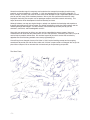
1
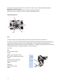
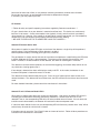
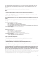
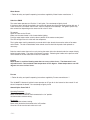
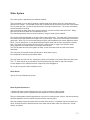
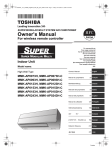
Revision 12A-0711
Owner’s Manual
Almost three decades ago, this company was founded on the concept that camping should be easy,
practical, and most importantly…enjoyable. In 1983, we pioneered the first solid wall, collapsible, “A
frame” camper, and every year since we have refined and developed it into a dependable product that will
provide you with many years of outdoor pleasures. We say this with confidence because the same
employees that build your campers use our prototype campers to do field research and testing. This
helps advance the Aliner development in both functionality and ease.
Although imitators can copy our original designs, nobody can duplicate the knowledge and experience
that goes into building every Aliner camper. Our skilled assemblers use only the finest products and the
newest lightweight technologies. We also carefully select dealerships that will provide you with
courteous, convenient, and knowledgeable services.
Along with your purchase of an Aliner, you also receive unparalleled customer support. Not many
manufacturers can boast that they allow owners to call in with questions, comments, part orders, or just to
receive help on periodic maintenance. We are here to provide you with a service that can take any
apprehension out of that long awaited cross country sightseeing trip.
A lot of things have changed since our first Aliner in 1983, but the founding concept and our ongoing
commitment to provide you with the finest solid wall “A frame” camper remains unchanged. We are just as
proud of our campers now as we were then and we thank you for purchasing our product.
The Aliner Team,
-2-
Table of Contents
1) Safety information and Disclaimer ------------------------ Page 4
i) Reporting Safety Defects ------------------------- Page 4
2) Chassis ---------------------------------------------------------- Page 5
i) Tires--------------------------------------------------------------- Page 5
ii) Axles -------------------------------------------------------------- Page 6
iii) Brakes ------------------------------------------------------------ Page 7
iv) Frame------------------------------------------------------------- Page 8
v) Coupler----------------------------------------------------------- Page 8
vi) Stabilizer --------------------------------------------------------- Page 9
vii) Step --------------------------------------------------------------- Page 9
3) Main Camper Assembly ------------------------------------- Page 10
i) Floor -------------------------------------------------------------- Page 10
ii) Sidewalls--------------------------------------------------------- Page 10
iii) Extrusions ------------------------------------------------------- Page 10
iv) Seals-------------------------------------------------------------- Page 10
v) Lights ------------------------------------------------------------- Page 10
vi) Fire Extinguisher----------------------------------------------- Page 10
vii) Skylights -------------------------------------------------------- Page 11
viii) Vents-------------------------------------------------------------- Page 11
4) Standard Electrical Features ------------------------------- Page 12
i) Converter -------------------------------------------------------- Page 12
ii) Battery------------------------------------------------------------ Page 12
5) Propane System ----------------------------------------------- Page 13
i) Tanks ------------------------------------------------------------- Page 13
ii) LP Detector ----------------------------------------------------- Page 14
iii) Stove-------------------------------------------------------------- Page 15
iv) Water Heater --------------------------------------------------- Page 16
v) Furnace ---------------------------------------------------------- Page 16
6) Water System -------------------------------------------------- Page 17
i) Heater ------------------------------------------------------------ Page 17
ii) Maintenance ---------------------------------------------------- Page 17
7) Preparing to Go ------------------------------------------------ Page 19
i) Loading----------------------------------------------------------- Page 19
ii) Attaching to Tow Vehicle ------------------------------------ Page 20
iii) Break-Away Switch ------------------------------------------- Page 20
8) Arriving at Camp----------------------------------------------- Page 21
i) Raising the Roof ----------------------------------------------- Page 21
ii) High Wind Kit --------------------------------------------------- Page 21
iii) Connecting Utilities-------------------------------------------- Page 22
iv) Awning ----------------------------------------------------------- Page 23
v) VersaDine Set Up --------------------------------------------- Page 24
9) Breaking Camp ------------------------------------------------ Page 25
i) Lowering the Roof --------------------------------------------- Page 25
ii) Steps before Leaving ----------------------------------------- Page 25
10) Care and Cleaning -------------------------------------------- Page 25
11) 7 Way Wiring Diagram --------------------------------------- Page 26
12) Warranty --------------------------------------------------------- Page 27
13) Green Addendum --------------------------------------------- Page 28
14) Maintenance Log ---------------------------------------------- Page 29
15) Notes ------------------------------------------------------------- Page 30
16) Part Terminology ---------------------------------------------- Page 31
3
IMPORTANT SAFETY INSTRUCTIONS
PLEASE READ AND FOLLOW ALL RELATED OPERATIONAL MANUALS AND THE INSTRUCTIONS
IN THIS OWNER MANUAL BEFORE USE.
THIS OWNER’S MANUAL IS INTENDED TO ACT AS A GENERAL GUIDE FOR OPERATION. THIS
MANUAL IS SUBJECT TO CHANGE WITHOUT NOTICE AND MAY/MAY NOT INCLUDE
INFORMATION REGARDING YOUR CAMPER.
ALWAYS REFER TO THE SPECIFIC MANUFACTURER’S OWNER, OPERATIONS, AND SAFETY
MANUAL FOR OPTIONAL EQUIPMENT WHICH INCLUDES, BUT IS NOT LIMITED TO, FURNACES,
REFRIGERATORS, WATER HEATERS, COOKTOPS, AND DETECTORS.
SAVE All INSTRUCTIONS.
Unless noted, names and brands that may be used in this document are not used to indicate an
affiliation or endorsement between the proprietors of these names and brands and Columbia
Northwest, Inc. Those names and brands may be the trademarks or registered trademarks of
those parties or others.
Reporting Safety Defects
If you believe that your vehicle has a defect which could cause a crash or could cause injury
or death, you should immediately inform the National Highway Traffic Safety
Administration (NHTSA) in addition to notifying Columbia Northwest, Inc.
If NHTSA receives similar complaints, it may open an investigation, and if it finds that a
safety defect exists in a group of vehicles, it may order a recall and remedy campaign.
However, NHTSA cannot become involved in individual problems between you, your
dealer, or Columbia Northwest, Inc. To contact NHTSA, you may call the Vehicle
Safety Hotline toll-free at 1–888–327–4236 (TTY: 1–800–424–9153); go to
http://www.safercar.gov; or write to:
Administrator
NHTSA
1200 New Jersey Ave SE
Washington, DC 20590
You can also obtain other information about motor vehicle safety from
http://www.safercar.gov.
4
Chassis
**NOTE**
MECHANICAL MAINTENANCE SHOULD ONLY BE PERFORMED BY A QUALIFIED MECHANIC. IF
YOU DO NOT HAVE THE EXPERIENCE OR THE TOOLS TO SAFELY COMPLETE MAINTENANCE
PROCEDURES, PLEASE CONTACT YOUR DEALER. WE ASSUME NO LIABILITY FOR INJURIES OR
DAMAGES INCURRED AS A RESULT OF IRRESPONSIBLE, UNAUTHORIZED SERVICING.
Tires/ Air Pressure
Air pressure is the most important factor determining tire life and under inflation is the number one cause
of trailer tire failure.
Maintain recommended air pressure listed on the tire sidewall, and periodically inspect both tires for tread
wear and damage from road hazards.
All tires must be identical in size for the tires to properly manage the weight of the trailer.
All "ST" tires have a maximum speed rating of 65 mph.
The mileage expectation of a trailer tire is 5,000 to 12,000 miles.
It is suggested that trailer tires be replaced after three to four years of service regardless of tread depth or
tire appearance.
Maintenance
•Clean the tires using mild soap and water.
•Do not use tire-care products containing alcohol or petroleum distillates.
•Inspect the tires for any cuts, snags, bulges or punctures
Tire Sizes
Alite
4.80 x 12
990# / 90 psi
5 on 4.5 pattern
Sport / Scout / Ranger / Classic / Titanium
ST 175/80R13
1315# / 50 psi
5 on 4.5 pattern
Off Road / Expedition / Titanium / Dormer / Highwall
ST 205/75R14
1760# / 50 psi
5 on 4.5 pattern
It is important to maintain proper wheel mounting torque on your lug nuts. When possible, use a torque
wrench to prevent loose wheels and broken studs. Start all nuts by hand to prevent cross threading.
Tighten the lug nuts in stages. First, tighten to 20-25 ft. /lb., then to 50-60 ft. /lb., and finally to 85-90 ft. /lb.
-5-
Check lug nut torque before the first use, and after 25 and 75 miles. Check periodically thereafter.
White Rims use 13/16” lug nuts
Black plastic caps over white rim lugs are removed by pulling straight off.
Aluminum rims can use either 13/16” or ¾” lug nuts, dependent on style.
Tightening Sequence
Axle
**Follow all safety and specific operating instructions supplied by the Axle manufacturer.**
All models use the AL-KO rubber torsion axle which offers greater dampening than conventional spring
suspensions and allows each tire to move independently. This feature gives a smoother ride and
improved tracking and cornering over rough road conditions. In addition, this type of axle has no metal to
metal contact or springs, shackles, hangers, or U-bolts to wear out.
Axle Sizes
Alite
SF 19 w/ electric brakes
1000#
Sport / Scout / Ranger / Classic
SF 19 with or without electric brakes
2000#
Off Road / Dormer / Highwall
U29 w/ electric brakes
3000#
Expedition
U35 w/ electric brakes
3500#
-6-
Torsion
Swing arm
Axle Spindle
Electric Brakes
The electric brake option on your camper is similar to the brakes on your towing vehicle, with the
exception that the camper’s brakes are electromagnetic, while your towing vehicle’s brakes are hydraulic.
When the brakes in the towing vehicle are activated, your controller determines how hard they are being
pressed, and sends the appropriate current through the hitch wire to the brake assembly. As you depress
the brake pedal, the controller sends more current to the electromagnet, and the brake shoes press
harder into the brake drums, forcing the wheel to resist rotation. Releasing the brake pedal decreases
the current to the brake assembly, allowing the wheel to spin freely.
The brakes are self adjusting, but will need an initial manual adjustment after the first 200 miles. The
brakes should be inspected every 3000 miles.
Contact your dealer unless you have the tools and experience to do a brake inspection, adjustment, and
replacement.
Brake Adjustment:
•
•
•
•
•
•
•
•
•
Elevate the camper by positioning jacks under the frame 12” to 20” behind the axle. Use the jack
stands under the frame to support the camper any time it is elevated.
NEVER PLACE THE JACKS UNDER THE FLOOR OR USE THE STABILIZERS TO ELEVATE
THE CAMPER.
Do not remove the wheels or hub/drum assembly.
Locate the adjusting slot at the bottom of the backing plate and remove the protective cover.
While spinning the wheel, use a blade screwdriver to rotate the star wheel until there is a heavy
brake drag.
Loosen until the wheel turns freely.
Replace the protective plug.
Repeat adjustment steps for the other wheel.
Never adjust just one brake.
Brake Inspection:
The brake linings and magnets are subject to wear and require inspection every 6,000 miles or annually.
Replacement is necessary if the linings are worn (to within 1/16” or less), contaminated with grease or oil,
or abnormally scored or gouged. It is important to replace all linings (both wheels) at the same time to
maintain even braking action across the axle. Annually inspect the wires under the trailer and on the axle
for broken insulation or faulty connections. Repair or replace as necessary.
Bearing Inspection:
Wash all grease and oil from the bearing and cone using a suitable solvent. Dry the bearing with a clean,
lint free cloth and completely inspect each roller. Replace the bearing cone and cup if there are any signs
of pitting, wear, or corrosion. Repeat the inspection procedure for the inner bearing cone.
** ALWAYS REPLACE THE BEARING CONE AND CUP AS A PAIR.
**NOTE**
DO NOT MIX LITHIUM, CALCIUM, SODIUM, OR BARIUM COMPLEX GREASES DUE TO POTENTIAL
COMPATIBILITY PROBLEMS. WHEN CHANGING FROM ONE TYPE OF GREASE TO ANOTHER, IT
IS NECESSARY TO INSURE THAT ALL OF THE OLD GREASE HAS BEEN REMOVED.
-7-
Bearing Lubrication:
Proper adjustment and adequate lubrication of the bearings are essential to the longevity and
performance of your trailer axle. The bearings should be lubricated every 6000 miles or 6 months.
Procedure:
Remove the rubber plug from grease cap.
Insert grease gun on the grease zerk.
Pump until new grease begins to appear.
Replace rubber plug.
Frame
The main frame members are 2.0” x 3.0” 11 gauge box channel steel. The Expedition has the larger 2.0”
x 5” 11 gauge box channel steel main frame.
All frames have been powder coated rather than using conventional liquid paint to produce a high
specification coating which is relatively harder and more abrasion resistant. The powder coating process
also emits near zero volatile organic compounds (VOC), gives the ability to apply a much thicker coat
without running, and produces less hazardous waste during production.
No normal maintenance is required, but if the welds or scratches need attention, first remove any rust,
dirt, or grease and coat with gloss black touch up paint.
There is a 2” receiver located on the rear bumper for optional equipment. This receiver is designed for
light weight cargo with the load positioned close to the receiver and bumper.
DO NOT EXCEED 125 POUNDS total weight on the receiver.
Coupler
Your high quality coupler needs no adjusting or maintenance other than periodic oiling to ensure smooth
operation. All models use a coupler that receives a 2” ball.
Set the hitch height of the tow vehicle so that the trailer is being pulled in a horizontal position. The height
listed below is the optimal height after the tongue weight is resting on the hitch. Trailers must be towed
as level as possible for proper handling and weight distribution.
The Classic, Ranger, Scout, Sport, and Alite
Set ball height ~14” from ground to bottom of ball.
Set ball height ~17” from ground to top of ball.
Off Road and High Wall option
Set ball height ~18” from ground to bottom of ball.
Set ball height ~21” from ground to top of ball.
Expedition, Titanium
Set ball height ~19” from ground to bottom of ball.
Set ball height ~22” from ground to top of ball.
-8-
Attaching the Trailer to the Tow Vehicle
Classic, Ranger, Scout, Sport, Expedition
Position the receiver over the ball, and lift the tab handle of the hitch upward as you lower the jack. After
the ball is seated, allow the handle to return back down parallel to the frame. It will click, indicating that it
has locked onto the ball. Attach the safety chains, insert the camper plug into the towing vehicle
receptacle, and test the signal lighting. Raise the jack as far as it will go by turning the crank handle
clockwise. Remove the castor wheel by removing locking pin and sliding the wheel assembly downward.
The locking pin can be inserted into the hitch locking mechanism for storage and added security.
** Do not tow the vehicle with the front jack in the lowered position or with the wheel attached.
Alite
Position the receiver over the ball, and lift the tab handle of the hitch upward as you lower the jack. After
the ball is seated, allow the handle to return back down parallel to the frame. It will click, indicating that it
has locked onto the ball. Attach the safety chains, insert the camper plug into the towing vehicle
receptacle, and test the signal lighting. Raise the jack as far as it will go by turning the crank handle
clockwise. Raise the front jack by pulling handle pin and rotating jack, including the wheel, toward the
rear of the trailer. The pin will lock into place in the stowed position.
Stabilizers
Trailers are equipped with two front and two rear 22” low-profile, lightweight stabilizer jacks. The high
strength design allows for increased load stabilization and fine leveling. Each stabilizer has a corrosionresistant finish.
Included is one rust inhibitive, zinc-plated ¾ “speed crank handle for quick response of both the up and
down movement.
** Ranger and Scout models have two rear stabilizers only.
Oil the jacks periodically to ensure smooth operation.
Never use the stabilizers to raise the camper tires off the ground.
Always raise the stabilizers completely before travel.
Step
Classic, Ranger, Scout, Sport come with a single slide out 7.25” drop step. The 20” tread is perforated
and equipped with anti-slip safety strip for added traction.
Expedition models have a double step with the above features.
Always stow the step /steps before travel.
-9-
Main Camper Assembly
Floor
One solid piece of vinyl flooring covers the seamless PerforMax 500 wooden floor. PerforMax 500 is
specifically engineered to withstand outdoor elements by using waterproof resins in the wood and also by
laminating an Ovation overlay on the exterior side of the wood for even more moisture resistance.
The Ovation overlay is thermally bonded and is highly resistant to scratches and abrasions. However, if
damage does occur, it can be repaired easily by using one of the following methods:
Loctite Metal/ Concrete Epoxy, available at hardware stores. This product is dark gray and dries very
quickly.
Bondo Metal Filler, available at automotive stores. This product is red in color and dries quickly.
Both products bond well to the PerforMax floor and are resistant to moisture, heat and cold and can be
painted with an oil based primer.
Sidewalls
The sidewalls, the hinged “A” walls, and the front and rear roof are made from a composite material
known as foam core lamination. At our factory, we laminate 2.7 millimeter “superlite” paneling, 1”
polystyrene foam, and 1.30 millimeter fiberglass together with a urethane adhesive. The lamination is
then placed in a vacuum press. The resulting solid core product is lightweight, extremely strong, and
thermally insulated. This rigid 1 1/8” material also eliminates the weight and wall thickness of the stud
and bracing method. The exposed edges of the walls and roof are capped with anodized aluminum
extrusions. Exterior flanges, covers, vents, and baggage doors are affixed to the outside walls with
silicone and screws before finishing with a sealing bead of silicone around the perimeter.
Extrusions
All of the aluminum extrusions on the camper are anodized to resist weathering. This process
deliberately oxidizes the surface of the aluminum to form a protective film that is impervious to corrosion
under normal conditions.
Seals
All models contain varying sizes and shapes of both rubber and foam seals. These seals should be
inspected regularly for tears, rips, or deterioration. If seals need replaced, a kit is available from Aliner or
from your local dealership.
Lights
There are two separate lighting systems in your camper. The convenience lights require power from the
converter, battery, or the battery of the towing vehicle. The trailer signal lights receive power from the
towing vehicle’s brakes, turn signals, running lights, and reverse lights. You should test the trailer and
towing vehicle lighting systems before every outing.
Fire Extinguisher
Your camper is equipped with a fire extinguisher for your safety. Please follow the instructions on the fire
extinguisher for testing and operation.
- 10 -
Skylights
The optional skylights are made of tinted polycarbonate. Compared to glass, polycarbonate is lighter,
less fragile, and shatter resistant. Periodic inspection should be done to ensure the silicone caulking
around the skylight is intact with both the roof and the skylight.
General cleaning: Blow off dust, clean with water and mild soap solution
Annual cleaning: Use a cleaner specific for polycarbonate. We recommend NOVUS Plastic Clean &
Shine No. 1, NOVUS Fine Scratch Remover No. 2 & NOVUS Heavy Scratch Remover No. 3.
Do not use ammonia or abrasive polishes. Do not use gas or petroleum. Do not use auto polish unless
taking out deep scratch. Do not use Rain X.
Roof Vents
The roof vents are used for cooking ventilation and can also be used to help keep the camper more
comfortable on hot days. Open the roof vent by turning the crank counter-clockwise. Always lower and
lock the vent in the down position before travel.
Fan-tastic Vent
This optional roof vent features a fan to evacuate the hot air that collects inside the roof peak. Best
results can be achieved by closing all other roof vents and opening a window on the shaded side of the
camper. The roof vent must be open approximately 3” before the motor will operate. Always lower and
lock the vent in the down position before travel.
- 11 -
Standard Electrical Features
Converter
**Follow all safety and specific operating instructions supplied by Converter manufacturer.**
The converter changes standard household electrical power into 12 volt dc, the type of electrical power
necessary for the operation of RV appliances and recharging RV batteries. There are three modes of
operation that the converter automatically senses and then self adjusts.
Absorption / Normal mode: Nominal battery charge and supplies power to appliances.
Bulk / Charge mode: fast battery charge and supplies power to appliances.
Float / Trickle Charge mode: supplies a slight trickle charge to maintain battery charge during storage.
Please follow converter manual for operation and safety instructions.
Do not block the small, automatic cooling fan on the converter.
Auxiliary Battery
TO AVOID CONVERTER DAMAGE DO NOT REVERSE THE BATTERY POLARITY!
Caution: RV Batteries contain sulfuric acid. Handle with care.
An auxiliary battery enables you to operate 12-volt dc appliances without draining your tow vehicle battery
or plugging your converter into a 120volt AC receptacle. Lights, heater fans, water pumps, roof fans,
radios, and cigarette lighter receptacles can run on the auxiliary battery power. Air conditioners,
microwave ovens, and standard outlets operate exclusively on 120 volts AC and therefore cannot run
from auxiliary battery power.
Use a deep cycle battery because its design gives maximum performance between recharging without
damaging the battery.
Note: A deep cycle battery will take longer to recharge as compared to a regular automotive battery.
Secure the lug and wire that has the 20-amp in line fuse to the batteries positive terminal.
The lugs on the remaining two white wires connect to the batteries negative terminal.
** Do not reverse the polarity of the battery and 12 volt wires as damage can occur to the
converter and wiring system **
If there is an electrical problem, first check the 20-amp fuse at the battery then check the fuses located in
the converter.
Do not replace battery fuses with anything other than a 20-amp fuse.
Some models are equipped with an internal storage box for the battery. This dual vented battery box is
required to discharge the hydrogen gas produced during charging.
In cold weather, store the battery in a location where the temperature remains above freezing. Do not
charge or store your battery in the camper unless it is in its proper enclosure.
- 12 -
Ground Fault Circuit Interrupt (GFCI)
In accordance with RVIA standards as well as the NEC, your camper is equipped with a ground fault
circuit interrupt (GFCI). The GFCI receptacle is a safety device designed to protect against shock
hazards.
Test the GFCI monthly by pressing the test button on the outlet. After testing, press the reset button to
restore power to the receptacle and the branch circuits.
If you lose power to your outlets, check the GFCI to see if it needs reset. If the GFCI will not reset, check
to see if a breaker on the converter or campground supply has tripped.
LP (Liquid Petroleum) System
** NOTE**
THE FURNACE, REFRIGERATOR, STOVE, AND WATER HEATER BURN LP (LIQUEFIED
PETROLEUM) GAS DURING OPERATION. LP GAS IS A VERY RELIABLE, CONVENIENT, AND
AFFORDABLE FUEL. HOWEVER, THIS GAS IS EXTREMELY DANGEROUS WHEN SAFETY
PRECAUTIONS ARE IGNORED.
LP Gas Tanks
To remove the tanks (or bottles) for filling, turn the tank valves off. Make a note of the regulator vent
position. Disconnect the hose or fitting to the tank valve. Loosen the wing nuts under the mounting
bracket and lift the hold down rods out of the way. To transport or store the tank, install the plastic plug
into the valve body. This prevents dust, dirt, and moisture from collecting in the valve. This plug also
protects the threads. After filling the tanks, fasten them securely to the mounting bracket using the wing
nuts and hold down rods.
Checking for Leaks
A hissing sound, condensation, or LP odor may indicate a ruptured gas line, in which case you should
turn the tank valve off immediately and have the system service by an authorized service center.
Before checking for leaks, make sure all LP gas appliances are turned off. Put out all flames and sources
of sparks.
Turn the tank valve on and generously apply a mild soap and water solution to each connection. Bubbles
will appear if there is a leak. If it leaks at a fitting, simply tightening the fitting may stop the leak.
Caution: Do not over tighten the fitting as they may crack.
If the leak continues even after tightening, replace the fittings. Leaks around the seals or vents of the
regulator will require replacing the regulator.
After testing for leaks, purge the air in the gas lines by opening a valve until you detect the odor of LP
gas. Allow enough time for the gas to dissipate before lighting any appliances. Periodically inspect the
tanks for dents, cracks, and corrosion. Inspect the mounting hardware and hoses for signs of wear, and
replace if necessary.
Always keep the valve on the tank closed when not in use or when traveling.
Never fill a tank over 80%.
- 13 -
Never test for leaks with a flame, or use products containing ammonia or chlorine to test for leaks.
Do not store your tank in an enclosed place with extreme temperature changes.
If necessary, you may repaint your tank.
LP Detector
** Follow all safety and specific operating instructions supplied by Detector manufacturer. **
LP gas is heavier than air so your detector is mounted near floor level. This device runs continuously
from the 12 volt source. Current consumption is low (typically 10 mA), and will not drain your battery
during normal use. However, if the camper is not going to be used for long periods, you can temporarily
remove the in line fuse located near the battery to avoid unnecessarily draining.
** BE SURE TO REPLACE THE FUSE BEFORE USING THE CAMPER. **
Atwood LP Detector Series 2001
When power is applied, a green LED lights on the face of the detector, a single chirp will be produced,
and then there is a 30-second delay until the detector is enabled.
Normal operation displays a flashing green light every 8 seconds.
The gas detector is a safety device that sounds a loud alarm and produces a rapid flashing red LED when
it detects 2000 ppm of LP gas in the atmosphere. The alarm may be silenced by pressing the “test”
button. However, if unsafe conditions are still detected, the alarm will sound again in 4 minutes.
The detector is sensitive to other products, so to avoid false triggering, do not store damp articles or use
any chemicals, cleaning agents near it.
If low voltage is detected, the alarm will display a steady red LED. In this mode, the detector is non
functional until power is restored in excess of 10 volts.
The detector should be tested weekly during use. Press the “test” button until the alarm sounds, then
release the button. The detector will sound three times; the LED will flash Red, and then return to normal
mode.
For more detailed information, please consult the manufacturer’s instructions.
Atwood LP and CO Detector Model LPCO
When power is applied, allow three to 6 minutes for stabilization. After which, the power LED will be lit
indicating gas concentrations are being continuously monitored. If unsafe levels of LP or CO are
detected in the air, the corresponding LED will be lit and an audible alarm will sound. If the air levels fall
to within normal concentrations, the detector will reset itself to the normal power mode.
If a fault has been detected in the unit, the corresponding LED will flash every second and a “chirp” will be
emitted every 40 seconds until the fault is cleared.
If the alarm sounds, press the “Test / Reset” button and move to fresh air. Follow all other procedures as
indicated in the manufacturer’s instructions.
- 14 -
The detector should be tested weekly during use. The Test / Reset button will sound the alarm twice,
with 4 beeps in one second followed by 5 seconds of silence. This will test normal functions of the
detector.
For more detailed information, please consult the manufacturer’s instructions.
Stove
** Follow all safety and specific operating instructions supplied by Stove manufacturer. **
** NEVER OPERATE THE STOVE FOR COMFORT HEATING! BEFORE LIGHTING THE STOVE,
OPEN A WINDOW AND A ROOF VENT. “
Failure to observe these rules may result in potentially dangerous levels of carbon monoxide inside the
camper.
Your camper has been equipped with either a built in counter cook top or a two burner indoor/outdoor
cook top.
Atwood manual lighting instructions:
Make sure LP gas is on at the shutoff valve.
Press burner control inwards and turn counter-clockwise.
Immediately light the burner by holding a match or hand held spark igniter near the burner ports.
Extinguishing instructions:
Turn the appropriate burner knob clockwise to off.
SMEV lighting instructions:
Make sure LP gas is on at the shutoff valve.
Press in knob and turn to “ignite” position.
Keep the knob pressed in and push the ignition button.
Once the burner has remained lit, turn the knob to the desired flame.
Extinguishing instructions:
Turn the appropriate burner knob clockwise to off.
Indoor / Outdoor Stove instructions:
** Follow all safety and specific operating instructions supplied by stove manufacturer. **
For units equipped with the indoor/outdoor stove or grill:
** Do not operate indoor / outdoor stove or grill with optional awning erect. **
An extruded aluminum bracket, which holds the cook top or grill, is mounted on the rear door side of the
camper. Tilt the front of the grill up as you attach the rear pin into this bracket. Lower the grill down
slowly until the bracket supports the weight.
The flexible propane hose is then attached to a quick connect adapter located under the camper directly
below the grill. The quick connect has a security feature which will only allow the disconnection of the
hose if the valve lever is turned perpendicular to the hose. This would place the valve in the off position.
When used inside the camper, follow all instructions for operating cook top indoors.
The quick connect is located under the front driver side bunk or in some models under the sink area. The
quick connect has a security feature which will only allow the disconnection of the hose if the valve lever
is turned perpendicular to the hose. This would place the valve in the off position.
- 15 -
Water Heater
** Follow all safety and specific operating instructions supplied by Water Heater manufacturer. **
Suburban SW6D
The water heater operates on LP with a 12 volt igniter. Do not attempt to light by hand!
If the burner does not light immediately, the system will attempt two more times before ignition lock out. If
a lock out occurs, turn rocker switch to “off”, wait five seconds, and reattempt. The ignition system may
take several tries depending on the amount of air in the LP lines.
To operate:
Open the valve on the LP tank.
Make sure the water heater is full of water before lighting.
Push the water heater rocker switch to the on position at the master control panel.
The LED will light if there is a fault with the component.
The 6 gallon water tank is protected by an anode which helps absorb the corrosive action of hot water
and minerals. The rod will deteriorate under normal use and should be inspected and replaced as
necessary.
Drain the water heater when not in use by turning the water drain valve located under the camper directly
below the water heater. The water will evacuate via gravity. Releasing the handle on the pressure relief
valve located on the hot water tank will assist in water flow.
Caution
Water heater is capable of heating water that can cause serious burns. The thermostat is not
adjustable and is set to maintain water temperature of 135 degrees. Water temperatures over 125
degrees can cause serious burns.
Furnace
** Follow all safety and specific operating instructions supplied by Furnace manufacturer. **
The 16,000 BTU electronic ignition furnace operates on LP gas for its fuel source but also needs 12 volt
electric to operate the blower. Do not attempt to light by hand!
Atwood Hydro flame 7916-II
Operating Procedure:
Open the valve on the LP tank.
Move small switch located on the thermostat to the “on” position.
Set thermostat to desired setting.
To shut off:
Slide thermostat to lowest setting.
Move switch located on thermostat to the “off” position.
Close the LP valve on the tank when not in use.
- 16 -
Water System
The water system is operated by two different methods.
The first method of use is done by hooking a potable water hose directly to the city water port on the
outside of the camper. The lockable access door is located outside on the driver rear side of the camper.
The city water port has a screen to keep debris from entering the interior lines. The screen and washer
can be removed for cleaning.
After connecting the water hose and turning the water on, the lines and hot water tank will fill. Slowly
open the sink faucet to allow air to escape from the lines.
The onboard pump does not need to be turned on if using this water system method.
The second method of operation is using the fresh water holding tank. The water tank is filled using the
fresh water access port located to the right of the city water port. Insert a hose into the port and fill the 11
gallon tank. When full, turn on the water pump using the switch located on the master appliance control
panel. This will operate the 12 volt demand pump and push water into the lines and also the hot water
tank. The pump will shut off after 45 PSI pressure is reached and run again if the pressure drops.
Slowly open the sink faucet to allow air to escape from the lines.
The DSI Hot water tank will hold 6 gallons of water, so the fresh water tank will need to be refilled
afterwards.
The sink faucet and outside shower will operate on either water system.
Do not operate the demand pump without water.
The gray water from the sink runs directly to the drain valve located on the driver side by the wheel well.
The 1 ½ “drain cap can be unscrewed by hand for allowing the gray water to drain into a bucket.
A hose adapter can be added to the drain if required by the campground.
Be sure to re-secure the drain cap before travel.
Water Heater
See the LP (Liquid Petroleum) System
Water System Maintenance
* Sanitize the water system before the first use, as well as before and after storage.
* Winterize all water system components before exposure to freezing temperatures.
Failure to follow proper winterizing procedures can result in cracked pumps, faucets, and other plumbing
hardware problems which will not be covered under the warranty policy.
After the camping season and before the first freeze of the winter, it is important that you winterize your
Aliner. All water should be drained from the fresh water and hot water tanks, the water lines, outside
shower, and drains.
- 17 -
To winterize the water system:
Open the petcock under the floor below the water tank and allow all water to drain out.
Open the ¾“screw-off cap located under the camper and allow water to drain form the lines and hot water
tank. This water drain is placed at the lowest point in the system. Elevating the front of the camper,
opening the sink and shower faucets, and opening the pressure relief valve on the hot water system will
assist in draining.
Remove the anode rod from the hot water tank and replace it with a ¾ inch drain plug.
Open the 1 ½ gray water drain cap and allow remaining water to drain.
After all water is drained, the lines can be either be blown out using compressed air or refilled with special
nontoxic RV antifreeze available from your dealer.
Add roughly two gallons of RV antifreeze to the potable water tank and use the water pump to pump the
antifreeze through all of the water connections. Let at least a cup of antifreeze go down each drain to
protect the traps. Finally drain any remaining antifreeze from the tank and be sure that the water heater is
drained and left open.
In the spring, after the last frost, you must drain all the antifreeze from the system and sanitize the entire
water system. Fill the tank full of water and run the pump to pump fresh water through the entire system
including the water heater.
After all the antifreeze has been cleared out, use household bleach to sanitize the system.
All potable water systems (water suitable for drinking) should be sanitized before and after storage. Also,
sanitize water systems with new equipment, or systems that have been subjected to contamination.
Sanitizing disinfects the water system and helps to provide safe, clean water.
Multiply the potable water tank gallon capacity by .13 for a four hour treatment, or by .26 for a one hour
treatment. This will give the liquid ounces of common household bleach required for disinfecting the
water system.
Add the proper amount of bleach to a container with water and mix.
Pour the solution into the water tank and fill the tank with potable water. Turn on the electric pump and
open all faucets including showers. Shut off the faucets when you smell chlorine.
Allow the proper treatment time (as determined in step 1) before draining the tank and refilling with
potable water.
** PURGE THE PLUMBING OF ALL BLEACH SOLUTION. **
The sanitizing procedure outlined above is in conformance with the approved procedures of RVIA ANSI
A119.2 and the U.S. Public Health Service.
Other Storage notes:
Keep tongue elevated.
Remove battery.
Remove LP tanks for storage.
- 18 -
Preparing to Go
The Aliner line of products has been designed for use in virtually all environments; however some
conditions may require extra caution or care to prevent damaging your camper.
Some owners use their campers in extremely cold temperatures. The insulated walls are perfectly suited
for this type of use, however the extreme temperature differences from inside and outside the camper can
cause condensation, particularly on aluminum. This moisture can freeze between the seals and the
extrusions and thus damage the seals if the camper walls or roof is lowered while still frozen.
We recommend that if using your camper under these conditions, you should spray the weather-stripping
and extrusions with silicone spray or Rain X. These products will help prevent the seals from freezing to
the extrusions.
The clearance produced from the optional Off Road axle makes it more suited for rough terrain travel;
however damage from collision with trees, underbrush, rocks, and other objects is not covered under
warranty.
Your camper features solid wall construction which makes it far more tolerant of windy conditions than
tent campers; however we do not recommend setting up the Aliner in high winds. The hinged panels can
be damaged during set up, and there is also an increased risk of personal injury under these
circumstances.
Balance the Load
Loading improperly can adversely affect handling while towing. Try to distribute your camping gear so the
hitch weight is 10-20 % of the gross vehicle weight. (TOTAL WEIGHT OF THE LOADED CAMPER)
The diagram below shows how the position of objects will affect the hitch weight. For instance if 50 lbs. of
camping gear were loaded into the front of the camper, the hitch weight would increase by about 30 lbs.
(50 lbs. x 60%=30 lbs.)
Ideally, whenever possible the heaviest objects should be stored near the axle, directly over the frame
members.
Balance Across the Axle
Handling can also be affected by grossly uneven loading across the axle. Most of the appliances are
mounted on the sink side of the camper, so stowing a proportionate amount of your camping gear at the
door side helps to equalize the weight across the axle. Failure to balance the load will promote uneven
tread wear.
- 19 -
Attaching the Trailer to the Tow Vehicle
Classic, Ranger, Scout, Sport, Expedition
Position the receiver over the ball, and lift the tab handle of the hitch upward as you lower the jack. After
the ball is seated, allow the handle to return back down parallel to the frame. It will click, indicating that it
has locked onto the ball. Attach the safety chains, insert the camper plug into the towing vehicle
receptacle, and test the signal lighting. Raise the jack as far as it will go by turning the crank handle
counter clockwise. Remove the castor wheel by removing locking pin and sliding the wheel assembly
downward. The locking pin can be inserted into the hitch locking mechanism for storage and added
security.
** Do not tow the vehicle with the front jack in the lowered position or with the wheel attached.
Alite
Position the receiver over the ball, and lift the tab handle of the hitch upward as you lower the jack. After
the ball is seated, allow the handle to return back down parallel to the frame. It will click, indicating that it
has locked onto the ball. Attach the safety chains, insert the camper plug into the towing vehicle
receptacle, and test the signal lighting. Raise the jack as far as it will go by turning the crank handle
counter clockwise. Raise the front jack by pulling handle pin and rotating jack, including the wheel,
toward the rear of the trailer. The pin will lock into place in the stowed position.
Hooking up the Break-Away Switch:
The break-away switch is an additional security feature that engages the trailers brakes should the trailer
become disconnected from the tow vehicle.
Note: the trailer must have an auxiliary battery connected for the break away to function.
Connect the cable from the break away switch to the tow vehicle. We suggest a secure area such as
where the safety chains are connected to the tow vehicle.
The break away cable should have enough slack when connected to enable movement and turning.
- 20 -
Arriving at Camp
Position your camper so it is level front to back and side to side. If adjustment is necessary, use leveling
boards under the wheels and raise or lower the tongue jack.
Lower the front and rear stabilizers.
Do not use the front and rear stabilizers to level the camper. The stabilizers should be lowered into
position after the camper is leveled. The pads of the stabilizers should be firmly on the ground, but not to
the point of raising the camper.
Position wheel chocking if needed.
Lower the step(s).
Raising the Roof
The maintenance-free lift system consists of four large springs designed to balance the weight of the
roofs, two steel hinges at the pivoting ends of the roof, and shock cords at the top of the roofs which help
prevent the roofs from overextending.
Undo the roof latches on both sides of the camper. The roofs will spring up slightly.
Lift the back roof. The roofs will elevate with little effort and lock into place.
Open the bottom door and lift the top door as you step into the camper. Carefully lift the door side “A”,
making sure not to hit the top door extrusion on the roof extrusion. Lock the “A” into position using the “A”
latches on the front and rear angles.
Raise the sink side “A” and lock into position using the forward and rear “A” latches.
** ALWAYS LATCH THE WALLS IN PLACE **
Align the top door over the bottom door and latch the door halves together using the sash lock.
High Wind Kit:
The high wind kit is an optional device which adds additional protection when camping in high winds.
WARNING: Caution must be used even with the high wind kit in storm conditions. Common sense and
good judgment should be the guide as to when the unit can be safely opened in unfavorable weather.
We do not define high wind limitations because there are too many variables. Proximity to buildings, other
RV's, and landscape can alter the wind speed drastically. The physical condition of the person setting up
the camper is also a factor. As a general rule of thumb, if you would be nervous to ride a bicycle because
of wind, or believe you would have trouble holding a large sheet of plywood, then you should exercise
caution setting up or closing the camper. When possible, point the front of the camper into the wind.
- 21 -
Connect Utilities:
Fill fresh water holding tank by inserting a clean hose into the large capped opening at the water fill
compartment, located on the driver side of the camper.
Connect hose to city water connection at same water fill location.
Slowly open sink faucet to bleed out any air in the lines. If only using fresh water holding tank and not city
water, the pump switch located on the master control panel must be turned on. Do not operate the pump
unless there are at least 1 ½ inches of water in the potable water holding tank. The pump is not
necessary and should not be turned on if using the city water connection.
Access the electrical shore power cord on the driver’s side of the camper and plug into the campground’s
30 amp outlet. An adapter can be used to plug directly into a standard household 15 or 20 amp outlet.
Turn on propane using the valves on the LP tank(s) located on the front of the camper. On units
equipped with dual propane tanks, the regulator will automatically switch from an empty cylinder to the full
one as long as both valves are open.
Attach the optional outdoor grill to the mounting bracket on the door side of the camper using the
interlocking tabs. The flexible propane hose can then be attached by using the quick connect located on
the underside of the camper, below the mounting bracket. The valve handle must be in the off position
for the hose to connect and disconnect. The valve position is perpendicular to the line in the “off” position
and parallel to the line in the “on” position.
When using the indoor/ outdoor grill inside, position stove on a flat counter and attach the flexible LP line
to the quick connect located either inside the front driver bunk or behind the access door under the sink,
dependant on your model.
Most units are not equipped with a gray water holding tank. The sink is drained directly to the outside.
The cap for this drain is located on the driver underside of the camper.
If the campground requires a hose drain, plumbing adapters can be purchased to reduce the 1 ½ inch
opening to fit a standard water hose.
There is a 75 ohm coaxial TV connector located on the outer driver side which will fit standard cable
connectors. A connector is located on the interior as well for convenient television plug in.
Cassette Toilet Operation:
See specific manual supplied.
- 22 -
Optional Fast Pack Awning Set Up
** DO NOT USE WITH INDOOR / OUTDOOR STOVE OR GRILL. **
With door side “A” wall in the traveling position, lay out the awning with the straight side toward the
camper.
Place the awning’s center opening over the “A” wall peak and lock the “A” wall in the upright position
making sure the edges of the awning are sandwiched between the “A” wall and the inside roof extrusions.
Insert flexible support rods and attach anchor cords.
- 23 -
VersaDine Positioning:
See illustration:
- 24 -
Breaking Camp:
Lowering the Roof
Before lowering the roof:
Make sure the interior lights are turned off.
All flames are extinguished.
All vents and skylights are closed and locked.
Back rest seat cushions are down.
Windows are closed.
The sink faucet is lowered down to the towing position.
Remove any objects from the countertops.
Starting with the door side “A”, disengage the rear “A” latch. Then disengage the rear sink side “A” latch,
followed by the front sink side “A” latch.
Carefully lower the “A” until it stops in the horizontal position by resting on the door side countertop.
** Models without a door side counter will have a collapsible leg on the “A” wall which must be locked in
position before lowering the wall. **
At the door side “A”, uncouple the top half of the door from the bottom half, unlock the door handle, and
open the top half of the Dutch door completely. Disengage the front “A” latch.
Maintain pressure on the wall until you are positioned just inside the door. Carefully lower the “A” as you
simultaneously go through the upper door opening. Do not scrape the top of the door on the roof
extrusion.
Rest the “A” wall carefully in the horizontal position on top of the sink side wall.
Exit the camper and close the top and bottom door.
Grasp the rear roof and tug downward to collapse the roofs. Keep hands behind the black seal as the
roofs collapse upon one another. Buckle the roof latches.
As you buckle the roof latches, observe the rubber roof gasket and the front roof extrusion. The gasket
should compress about 1/8”.
If needed, adjust the roof latches by rotating the buckle clockwise to tighten.
Before Leaving:
Disconnect all campground utilities.
Raise all the stabilizers.
Raise the step(s).
Attach to tow vehicle hitch and lock into position.
Attach safety chains.
Attach 12 volt pigtail cord to tow vehicle.
Raise the front jack completely.
Remove the front castor wheel.
Remove wheel chocking.
Care and Cleaning
The exterior of the camper can be cleaned with mild soap and water.
Do not pressure wash.
We recommend dry cleaning the curtains, fabric, and cushion upholstery when needed
The skylights and vents should be cleaned with mild soap and water. Use only a cleaning agent safe for
polycarbonates.
A soft lined cover can be used to shield the camper when in storage. Additional protection, such as a soft
towel should be used to protect the skylights from abrasions.
- 25 -
- 26 -
NEW RECREATIONAL VEHICLE LIMITED WARRANTY
Warranty Coverage: Details of this warranty apply to the following brands produced by Columbia
Northwest; Aliner, and T.R.E. Columbia Northwest Inc. will make repairs to defects in workmanship or
materials, free of charge for one year from the retail purchase date. Because of design changes and
improvements, we reserve the right to substitute parts, materials or components with ones of equal value
and quality. This warranty applies only to the original retail purchaser of a new product from an authorized
Columbia Northwest Dealer.
The owner is responsible to maintain the camper in accordance with the instructions provided in the
owner’s manual. Failure to follow proper procedures and seasonal maintenance schedules may void your
warranty.
Warranty Services: To obtain warranty services, contact an authorized Columbia Northwest Dealer or an
approved service center. For locations of our approved representatives call the factory Customer Service
Manager at (724) 423-7440. If your warranty is not registered, you will be asked to provide a sales receipt
to document the date and location of purchase.
Warranty Claim Procedures: Upon discovery of a defect please notify Columbia Northwest, Inc. within
three days by registered letter. Please provide name, address, description of the problem, vehicle
identification number of unit, model and where you may be contacted during business hours.
Excluded from Coverage:
• Equipment or parts warranted by the original manufacturer separately; to include tires, axles, frames, all
appliances and converters.
• Damages resulting from misuse, abuse, collision, improper repairs, overloading, neglect and improper
maintenance.
• Damages resulting from alteration, or installation of additional equipment without proper authorization to
the electrical, gas, plumbing or structural systems.
• Normal wear, fading, or deterioration of fabrics, flooring and other materials.
• Normal wear of metal parts including weathering, discoloration, surface corrosion of unpainted surfaces,
and minor cosmetic blemishes occurring from normal use.
• Any product used outside of its intended customary purpose.
• Any unregistered product not normally used in the United States of America or Canada.
• Any product used as a rental.
• Any promises made by any person beyond those stated in this warranty.
• Condensation on any window or other parts or any other results of condensation.
Columbia Northwest Inc. shall not be liable for incidental or consequential damages, such as expenses
for transportation, lodging, damage to personal property, loss of personal property, loss of use of your
product, inconvenience or loss of income.
Some states do not allow the exclusion or limitation of incidental or consequential damages, so the above
limitation may not apply to you.
Legal Procedures: In addition to the provisions of this warranty, the retail purchaser has available the
legal remedies provided by the Magnuson-Moss Warranty Act and any applicable State statutes.
Implied warranties, including any warranty of merchantability or fitness of a product for a
particular purpose, are limited in duration to the term of this written warranty. Some states do not
allow limitations on how long an implied warranty lasts, so the above limitation may not apply to you. This
warranty gives you specific legal rights, and you may also have other rights, which vary from state to
state.
Columbia Northwest Inc. warrants this recreational vehicle to be in accordance with the provisions of
chapter 74-169, Florida Statutes, for a period of (12) months.
We want you to be satisfied with your new camper. For further help or information contact the factory.
Columbia Northwest, Inc. 1297 Kecksburg Road, Mt. Pleasant, PA 15666 or by Phone: (724) 423-7440
Fax: (724) 423-8485
- 27 -
GREEN ADDENDUM FOR RECREATIONAL VEHICLES Practices & Products In an effort to conserve paper, this document can be viewed at www.tragreen.com/resources.aspx
Topics Addressed:
Energy Efficient Lighting
Energy Conservation
Water Conservation
Hazardous Materials
Organic Products
Importance of Proper Operation & Maintenance
Maintenance Checklist
- 28 -
Maintenance Log
Date
Mileage
Service
- 29 -
Notes
- 30 -
1 Sidewall
2 Rear Roof
3 Peak
4 Front Roof
5 Waterproof Dual Outlet
6 Roof Vent
7 Grab Handle
8 LP (Liquid Propane) Tank
9 Baggage Door Lock Assembly
10 Tongue Jack
11 Breakaway Switch
12 Stabilizer Jack
13 Single Step
14 Roof Latch
15 Entry Door Handle
16 Porch Light
17 Fender Skirt
18 Tongue/Ball Joint
19 Fantastic Fan
20 Outside Stove Bracket
21 Caster Wheel
22 Safety Chains
23 Baggage Door
24 Skylight (21” x 62”)
25 Spring Cover
26 Amber Marker Light
27 Red Marker Light
28 Door Holder Assembly
29 AC/AC Cover
30 Outside Shower
31 Refrigerator Vents
32 Electrical Hatch
33 Exterior Coax
34 Water Hatch
35 Corner Cap
36 Hinge Trim/Seal
- 31 -
1
1297 Kecksburg Road
Mt. Pleasant, PA 15666
(P) 724.423.7440
(F) 724.423.8485
www.aliner.com