1
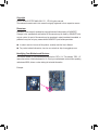
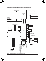
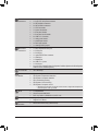
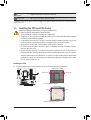
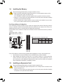
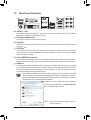
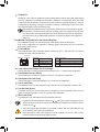
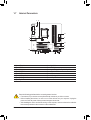
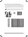
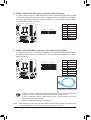
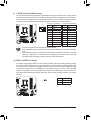
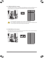
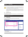
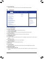
GA-Q67M-D2H-B3 User's Manual Rev. 1002 12ME-Q67M2HB-1002R Motherboard GA-Q67M-D2H-B3 Apr. 8, 2011 GA-Q67M-D2H-B3 Motherboard Apr. 8, 2011 Copyright © 2011 GIGA-BYTE TECHNOLOGY CO., LTD. All rights reserved. The trademarks mentioned in this manual are legally registered to their respective owners. Disclaimer Information in this manual is protected by copyright laws and is the property of GIGABYTE. Changes to the specifications and features in this manual may be made by GIGABYTE without prior notice. No part of this manual may be reproduced, copied, translated, transmitted, or published in any form or by any means without GIGABYTE's prior written permission. In order to assist in the use of this product, carefully read the User's Manual. For product-related information, check on our website at: http://www.gigabyte.com Identifying Your Motherboard Revision The revision number on your motherboard looks like this: "REV: X.X." For example, "REV: 1.0" means the revision of the motherboard is 1.0. Check your motherboard revision before updating motherboard BIOS, drivers, or when looking for technical information. Example: Table of Contents GA-Q67M-D2H-B3 Motherboard Layout.........................................................................5 GA-Q67M-D2H-B3 Motherboard Block Diagram............................................................6 Chapter 1 Hardware Installation......................................................................................7 1-1 1-2 1-3 1-4 1-5 1-6 1-7 Installation Precautions.................................................................................... 7 Product Specifications...................................................................................... 8 Installing the CPU and CPU Cooler............................................................... 10 Installing the Memory......................................................................................11 Installing an Expansion Card...........................................................................11 Back Panel Connectors.................................................................................. 12 Internal Connectors........................................................................................ 14 Chapter 2 BIOS Setup...................................................................................................23 2-1 2-2 2-3 2-4 2-5 2-5 2-6 The POST screen........................................................................................... 23 The Main Menu............................................................................................... 23 Advanced........................................................................................................ 24 Chipset............................................................................................................ 26 Boot................................................................................................................. 26 Security........................................................................................................... 27 Save & Exit..................................................................................................... 28 Chapter 3 Drivers Installation........................................................................................29 Installing Chipset Drivers........................................................................................... 29 Chapter 4 Appendix.......................................................................................................29 Configuring SATA Hard Drive(s)................................................................................ 29 -4- DDR3_4 DDR3_3 ATX_12V DDR3_2 KB_USB DDR3_1 GA-Q67M-D2H-B3 Motherboard Layout VGA_DVI Level Shifter DP_HDMI_SPDIF LGA1155 Level Shifter ATX R_USB SYS_FAN LPT USB_LAN BAT CPU_FAN GA-Q67M-D2H-B3 PCIEX16 PCI1 Intel 82579 BIOS PCI2 Intel® Q67 PCIEX4 iTE IT8728 TPM_IC (Note) AUDIO CLR_CMOS SATA3_0 SATA3_1 SATA2_2 SATA2_3 SATA2_4 SATA2_5 SPDIF_O CODEC DEBUG_PORT F_AUDIO F_USB4 F_USB3 F_USB2 F_USB1 F_PANEL COMA COMB Box Contents GA-Q67M-D2H-B3 motherboard Motherboard driver disk User's Manual Two SATA cables I/O Shield * The box contents above are for reference only and the actual items shall depend on the product package you obtain. (Note) This feature is optional due to different regional policy. -5- GA-Q67M-D2H-B3 Motherboard Block Diagram 1 PCI Express x16 CPU CLK+/- (100 MHz) LGA1155 CPU DDR3 1333/1066/800 MHz Dual Channel Memory x16 PCI Express Bus 1 PCI Express x4 PCIe CLK (100 MHz) FDI Interface DMI Interface PCIe CLK (100 MHz) DisplayPort LAN HDMI RJ45 DVI-D Intel D-Sub 82579 PCI Express Bus x4 x1 BIOS Intel® Q67 2 SATA 6Gb/s 4 SATA 3Gb/s 14 USB 2.0/1.1 PCI Bus LPC Bus LPT iTE IT8728 CODEC COM Ports PCI CLK (33 MHz) (Note) This feature is optional due to different regional policy. -6- S/PDIF Out 2 PCI Surround Speaker Out Center/Subwoofer Speaker Out Side Speaker Out MIC Line Out Line In PS/2 KB/Mouse TPM (Note) Chapter 1 Hardware Installation 1-1 Installation Precautions The motherboard contains numerous delicate electronic circuits and components which can become damaged as a result of electrostatic discharge (ESD). Prior to installation, carefully read the user's manual and follow these procedures: •• Prior to installation, do not remove or break motherboard S/N (Serial Number) sticker or warranty sticker provided by your dealer. These stickers are required for warranty validation. •• Always remove the AC power by unplugging the power cord from the power outlet before installing or removing the motherboard or other hardware components. •• When connecting hardware components to the internal connectors on the motherboard, make sure they are connected tightly and securely. •• When handling the motherboard, avoid touching any metal leads or connectors. •• It is best to wear an electrostatic discharge (ESD) wrist strap when handling electronic components such as a motherboard, CPU or memory. If you do not have an ESD wrist strap, keep your hands dry and first touch a metal object to eliminate static electricity. •• Prior to installing the motherboard, please have it on top of an antistatic pad or within an electrostatic shielding container. •• Before unplugging the power supply cable from the motherboard, make sure the power supply has been turned off. •• Before turning on the power, make sure the power supply voltage has been set according to the local voltage standard. •• Before using the product, please verify that all cables and power connectors of your hardware components are connected. •• To prevent damage to the motherboard, do not allow screws to come in contact with the motherboard circuit or its components. •• Make sure there are no leftover screws or metal components placed on the motherboard or within the computer casing. •• Do not place the computer system on an uneven surface. •• Do not place the computer system in a high-temperature environment. •• Turning on the computer power during the installation process can lead to damage to system components as well as physical harm to the user. •• If you are uncertain about any installation steps or have a problem related to the use of the product, please consult a certified computer technician. -7- Hardware Installation 1-2 Product Specifications CPU Support for Intel® Core™ i7 processors/Intel® Core™ i5 processors/ Intel® Core™ i3 processors/Intel® Pentium® processors/Intel® Celeron® processors in the LGA1155 package (Go to GIGABYTE's website for the latest CPU support list.) L3 cache varies with CPU Chipset Intel® Q67 Express Chipset Memory 4 x 1.5V DDR3 DIMM sockets supporting up to 32 GB of system memory Onboard Graphics *Due to Windows 32-bit operating system limitation, when more than 4 GB of physical memory is installed, the actual memory size displayed will be less than 4 GB. Dual channel memory architecture Support for DDR3 1333/1066/800 MHz memory modules Support for non-ECC memory modules (Go to GIGABYTE's website for the latest supported memory speeds and memory modules.) Integrated in the Chipset: - 1 x D-Sub port - 1 x DVI-D port, supporting a maximum resolution of 1920x1200 * The DVI-D port does not support D-Sub connection by adapter. Audio - 1 x HDMI port, supporting a maximum resolution of 1920x1200 - 1 x DisplayPort, supporting a maximum resolution of 2560x1600p Realtek ALC889 codec High Definition Audio 2/4/5.1/7.1-channel LAN 1 x Intel 82579 chip (10/100/1000 Mbit) Expansion Slots 1 x PCI Express x16 slot, running at x16 (PCIEX16) 1 x PCI Express x16 slot, running at x4 (PCIEX4) (All PCI Express slots conform to PCI Express 2.0 standard.) 2 x PCI slots Multi-Graphics Support for AMD CrossFireX™ technology *The PCIEX16 slot operates at up to x4 mode when AMD CrossFireX™ is enabled. Technology Storage Interface Chipset: - 2 x SATA 6Gb/s connectors (SATA3_0~SATA3_1) supporting up to 2 SATA 6Gb/s devices - 4 x SATA 3Gb/s connectors (SATA2_2~SATA2_5) supporting up to 4 SATA 3Gb/s devices - Support for RAID 0, RAID 1, RAID 5, and RAID 10 * When a RAID set is built across the SATA 6Gb/s and SATA 3Gb/s channels, the system performance of the RAID set may vary depending on the devices being connected. USB Chipset: -Up to 14 USB 2.0/1.1 ports (6 ports on the back panel, 8 ports available through the internal USB header) Hardware Installation -8- Internal Connectors Back Panel Connectors 1 x 24-pin ATX main power connector 1 x 4-pin ATX 12V power connector 2 x SATA 6Gb/s connectors 4 x SATA 3Gb/s connectors 1 x CPU fan header 1 x system fan header 1 x front panel header 1 x front panel audio header 4 x USB 2.0/1.1 headers 1 x debug card header 1 x parallel port header 2 x serial port headers 1 x clearing CMOS jumper 1 x PS/2 keyboard/mouse port 1 x D-Sub port 1 x DVI-D port 1 x optical S/PDIF Out connector 1 x HDMI port 1 x DisplayPort 6 x USB 2.0/1.1 ports 1 x RJ-45 port 6 x audio jacks (Center/Subwoofer Speaker Out/Rear Speaker Out/Side Speaker Out/Line In/Line Out/Microphone) I/O Controller iTE IT8728 chip Hardware Monitor System voltage detection CPU/System temperature detection CPU/System fan speed detection CPU overheating warning CPU/System fan fail warning CPU/System fan speed control BIOS Unique Features Bundled Software *Whether the CPU/system fan speed control function is supported will depend on the CPU/system cooler you install. 1 x 64 Mbit flash Use of licensed AMI BIOS PnP 1.0a, DMI 2.0, SM BIOS 2.4, ACPI 1.0b Support for Xpress Install Support for Q-Share Norton Internet Security (OEM version) -9- Hardware Installation Operating System Support for Microsoft ® Windows 7/Vista/XP Form Factor Micro ATX Form Factor; 24.4cm x 24.4cm * GIGABYTE reserves the right to make any changes to the product specifications and product-related information without prior notice. 1-3 Installing the CPU and CPU Cooler Read the following guidelines before you begin to install the CPU: •• Make sure that the motherboard supports the CPU. (Go to GIGABYTE's website for the latest CPU support list.) •• Always turn off the computer and unplug the power cord from the power outlet before installing the CPU to prevent hardware damage. •• Locate the pin one of the CPU. The CPU cannot be inserted if oriented incorrectly. (Or you may locate the notches on both sides of the CPU and alignment keys on the CPU socket.) •• Apply an even and thin layer of thermal grease on the surface of the CPU. •• Do not turn on the computer if the CPU cooler is not installed, otherwise overheating and damage of the CPU may occur. •• Set the CPU host frequency in accordance with the CPU specifications. It is not recommended that the system bus frequency be set beyond hardware specifications since it does not meet the standard requirements for the peripherals. If you wish to set the frequency beyond the standard specifications, please do so according to your hardware specifications including the CPU, graphics card, memory, hard drive, etc. Installing the CPU A. Locate the alignment keys on the motherboard CPU socket and the notches on the CPU. LGA1155 CPU Socket Alignment Key Alignment Key Pin One Corner of the CPU Socket LGA1155 CPU Notch Triangle Pin One Marking on the CPU Hardware Installation - 10 - Notch 1-4 Installing the Memory Read the following guidelines before you begin to install the memory: •• Make sure that the motherboard supports the memory. It is recommended that memory of the same capacity, brand, speed, and chips be used. (Go to GIGABYTE's website for the latest supported memory speeds and memory modules.) •• Always turn off the computer and unplug the power cord from the power outlet before installing the memory to prevent hardware damage. •• Memory modules have a foolproof design. A memory module can be installed in only one direction. If you are unable to insert the memory, switch the direction. Dual Channel Memory Configuration This motherboard provides four DDR3 memory sockets and supports Dual Channel Technology. After the memory is installed, the BIOS will automatically detect the specifications and capacity of the memory. Enabling Dual Channel memory mode will double the original memory bandwidth. The four DDR3 memory sockets are divided into two channels and each channel has two memory sockets as following: Channel A: DDR3_1, DDR3_2 Channel B: DDR3_3, DDR3_4 Dual Channel Memory Configurations Table Two Modules Four Modules DDR3_1 DS/SS -DS/SS DDR3_2 -DS/SS DS/SS DDR3_3 DS/SS -DS/SS DDR3_4 -DS/SS DS/SS DDR3_1 DDR3_2 DDR3_3 DDR3_4 (SS=Single-Sided, DS=Double-Sided, "- -"=No Memory) Due to CPU limitations, read the following guidelines before installing the memory in Dual Channel mode. 1. Dual Channel mode cannot be enabled if only one DDR3 memory module is installed. 2. When enabling Dual Channel mode with two or four memory modules, it is recommended that memory of the same capacity, brand, speed, and chips be used for optimum performance. For optimum performance, when enabling Dual Channel mode with two memory modules, we recommend that you install them in the DDR3_2 and DDR3_4 sockets. 1-5 Installing an Expansion Card Read the following guidelines before you begin to install an expansion card: • Make sure the motherboard supports the expansion card. Carefully read the manual that came with your expansion card. • Always turn off the computer and unplug the power cord from the power outlet before installing an expansion card to prevent hardware damage. - 11 - Hardware Installation 1-6 Back Panel Connectors USB 2.0/1.1 Port The USB port supports the USB 2.0/1.1 specification. Use this port for USB devices such as a USB keyboard/mouse, USB printer, USB flash drive and etc. PS/2 Keyboard/Mouse Port Use this port to connect a PS/2 mouse or keyboard. D-Sub Port The D-Sub port supports a 15-pin D-Sub connector. Connect a monitor that supports D-Sub connection to this port. DVI-D Port (Note) The DVI-D port conforms to the DVI-D specification and supports a maximum resolution of 1920x1200 (the actual resolutions supported depend on the monitor being used). Connect a monitor that supports DVI-D connection to this port. Optical S/PDIF Out Connector This connector provides digital audio out to an external audio system that supports digital optical audio. Before using this feature, ensure that your audio system provides an optical digital audio in connector. HDMI Port The HDMI (High-Definition Multimedia Interface) provides an all-digital audio/video interface to transmit the uncompressed audio/video signals and is HDCP compliant. Connect the HDMI audio/video device to this port. The HDMI Technology can support a maximum resolution of 1920x1200 but the actual resolutions supported depend on the monitor being used. • After installing the HDMI device, make sure the default device for sound playback is the HDMI device. (The item name may differ from operating system. Refer to the figure below for details.) • Please note the HDMI audio output only supports AC3, DTS and 2-channel-LPCM formats. (AC3 and DTS require the use of an external decoder for decoding.) In Windows 7, select Start>Control Panel>Hardware and Sound>Sound>Playback, set Intel(R) Display Audio to the default playback device. (Note) The DVI-D port does not support D-Sub connection by adapter. Hardware Installation - 12 - DisplayPort DisplayPort is one of the new generation interface technologies that delivers high quality digital imaging and audio, supporting bi-directional audio transmition. DisplayPort can support both DPCP and HDCP content protection mechanisms. Connect the audio/video device that supports DisplayPort to this port. The DisplayPort Technology can support a maximum resolution of 2560x1600p but the actual resolutions supported depend on the monitor being used. After installing the DisplayPort device, make sure the default device for sound playback is the DisplayPort device. (The item name may differ from operating system. For example, in Windows Vista, go to Start>Control Panel>Sound>Playback and set the DisplayPort device as the default playback device. Refer to the HDMI settings information on the previous page for the configuration dialog box.) Dual Monitor Configurations for the Onboard Graphics: This motherboard provides four video output ports: D-Sub, DVI-D, HDMI, and DisplayPort. Dual monitor configurations are supported in operating system environment only, but not during the BIOS Setup or POST process. RJ-45 LAN Port The Gigabit Ethernet LAN port provides Internet connection at up to 1 Gbps data rate. The following describes the states of the LAN port LEDs. Speed LED Connection/ Activity LED LAN Port Speed LED: State Orange Green Off Description 1 Gbps data rate 100 Mbps data rate 10 Mbps data rate Connection/Activity LED: State Description Blinking Data transmission or receiving is occurring On No data transmission or receiving is occurring Off LAN link is not established Center/Subwoofer Speaker Out Jack (Orange) Use this audio jack to connect center/subwoofer speakers in a 5.1/7.1-channel audio configuration. Rear Speaker Out Jack (Black) Use this audio jack to connect rear speakers in a 4/5.1/7.1-channel audio configuration. Side Speaker Out Jack (Gray) Use this audio jack to connect side speakers in a 7.1-channel audio configuration. Line In Jack (Blue) The default line in jack. Use this audio jack for line in devices such as an optical drive, walkman, etc. Line Out Jack (Green) The default line out jack. Use this audio jack for a headphone or 2-channel speaker. This jack can be used to connect front speakers in a 4/5.1/7.1-channel audio configuration. Mic In Jack (Pink) The default Mic in jack. Microphones must be connected to this jack. In addition to the default speakers settings, the ~ audio jacks can be reconfigured to perform different functions via the audio software. Only microphones still MUST be connected to the default Mic in jack ( ). •• When removing the cable connected to a back panel connector, first remove the cable from your device and then remove it from the motherboard. •• When removing the cable, pull it straight out from the connector. Do not rock it side to side to prevent an electrical short inside the cable connector. - 13 - Hardware Installation 1-7 Internal Connectors 1 4 13 3 5 2 15 6 7 10 9 1) 2) 3) 4) 5) 6) 7) 8) ATX_12V ATX CPU_FAN SYS_FAN BAT SATA3_0/1 SATA2_2/3/4/5 F_PANEL 14 11 8 9) 10) 11) 12) 13) 14) 15) 12 F_AUDIO SPDIF_O F_USB1/F_USB2/F_USB3/F_USB4 COMA/COMB LPT DEBUG_PORT CLR_CMOS Read the following guidelines before connecting external devices: •• First make sure your devices are compliant with the connectors you wish to connect. •• Before installing the devices, be sure to turn off the devices and your computer. Unplug the power cord from the power outlet to prevent damage to the devices. •• After installing the device and before turning on the computer, make sure the device cable has been securely attached to the connector on the motherboard. Hardware Installation - 14 - 1/2)ATX_12V/ATX (2x2 12V Power Connector and 2x12 Main Power Connector) With the use of the power connector, the power supply can supply enough stable power to all the components on the motherboard. Before connecting the power connector, first make sure the power supply is turned off and all devices are properly installed. The power connector possesses a foolproof design. Connect the power supply cable to the power connector in the correct orientation. The 12V power connector mainly supplies power to the CPU. If the 12V power connector is not connected, the computer will not start. To meet expansion requirements, it is recommended that a power supply that can withstand high power consumption be used (500W or greater). If a power supply is used that does not provide the required power, the result can lead to an unstable or unbootable system. 1 2 3 4 ATX_12V ATX_12V: Pin No. 1 2 3 4 Definition GND GND +12V +12V ATX: 12 24 1 13 Pin No. 1 2 3 4 5 6 7 8 9 10 11 12 Definition Pin No. 3.3V 13 3.3V 14 GND 15 +5V 16 GND 17 +5V 18 GND 19 Power Good 20 5VSB (stand by +5V) 21 +12V 22 +12V (Only for 2x12-pin ATX) 23 3.3V (Only for 2x12-pin ATX) 24 Definition 3.3V -12V GND PS_ON (soft On/Off) GND GND GND -5V +5V +5V +5V (Only for 2x12-pin ATX) GND (Only for 2x12-pin ATX) ATX - 15 - Hardware Installation 3/4)CPU_FAN/SYS_FAN (Fan Headers) The motherboard has a 4-pin CPU fan header (CPU_FAN), a 4-pin system fan header (SYS_FAN). Most fan headers possess a foolproof insertion design. When connecting a fan cable, be sure to connect it in the correct orientation (the black connector wire is the ground wire). The motherboard supports CPU fan speed control, which requires the use of a CPU fan with fan speed control design. For optimum heat dissipation, it is recommended that a system fan be installed inside the chassis. CPU_FAN: 1 CPU_FAN 1 Pin No. 1 2 3 4 Definition GND +12V /Speed Control Sense Speed Control SYS_FAN: SYS_FAN Pin No. 1 2 3 4 Definition GND +12V /Speed Control Sense Reserve •• Be sure to connect fan cables to the fan headers to prevent your CPU and system from overheating. Overheating may result in damage to the CPU or the system may hang. •• These fan headers are not configuration jumper blocks. Do not place a jumper cap on the headers. 5) BAT (Battery) The battery provides power to keep the values (such as BIOS configurations, date, and time information) in the CMOS when the computer is turned off. Replace the battery when the battery voltage drops to a low level, or the CMOS values may not be accurate or may be lost. You may clear the CMOS values by removing the battery: 111 Turn off your computer and unplug the power cord. 222 Gently remove the battery from the battery holder and wait for one minute. (Or use a metal object like a screwdriver to touch the positive and negative terminals of the battery holder, making them short for 5 seconds.) 333 Replace the battery. 444 Plug in the power cord and restart your computer. •• Always turn off your computer and unplug the power cord before replacing the battery. •• Replace the battery with an equivalent one. Danger of explosion if the battery is replaced with an incorrect model. •• Contact the place of purchase or local dealer if you are not able to replace the battery by yourself or uncertain about the battery model. •• When installing the battery, note the orientation of the positive side (+) and the negative side (-) of the battery (the positive side should face up). •• Used batteries must be handled in accordance with local environmental regulations. Hardware Installation - 16 - 6) SATA3_0/1 (SATA 6Gb/s Connectors, Controlled by Intel Q67 Chipset) The SATA connectors conform to SATA 6Gb/s standard and are compatible with SATA 3Gb/s and SATA 1.5Gb/s standard. Each SATA connector supports a single SATA device. The SATA3_0 and SATA3_1 connectors support RAID 0 and RAID 1. RAID 5 and RAID 10 can be implemented on the two connectors with the SATA2_2/3/4/5 connector (Note). SATA3_0 Pin No. 1 2 3 4 5 6 7 SATA3_1 7 1 Definition GND TXP TXN GND RXN RXP GND 7) SATA2_2/3/4/5 (SATA 3Gb/s Connectors, Controlled by Intel Q67 Chipset) 1 7 SATA2_4 SATA2_5 Definition GND TXP TXN GND RXN RXP GND Please connect the L-shaped end of the SATA cable to your SATA hard drive. • A RAID 0 or RAID 1 configuration requires at least two hard drives. If more than two hard drives are to be used, the total number of hard drives must be an even number. • A RAID 5 configuration requires at least three hard drives. (The total number of hard drives does not have to be an even number.) • A RAID 10 configuration requires four hard drives. (Note) When a RAID set is built across the SATA 6Gb/s and SATA 3Gb/s channels, the system performance of the RAID set may vary depending on the devices being connected. - 17 - DEBUGDEBUG PORT PORT 7 1 Pin No. 1 2 3 4 5 6 7 DEBUG PORT SATA2_3 DEBUGDEBUG PORT PORT SATA2_2 DEBUG PORT The SATA connectors conform to SATA 3Gb/s standard and are compatible with SATA 1.5Gb/s standard. Each SATA connector supports a single SATA device. The Intel Q67 Chipset supports RAID 0, RAID 1, RAID 5, and RAID 10. Hardware Installation 8) F_PANEL (Front Panel Header) Connect the power switch, reset switch, speaker, and system status indicator on the chassis to this header according to the pin assignments below. Note the positive and negative pins before connecting the cables. Power Switch Speaker SPEAK- MSG+ MSGPW+ PW- Message/Power/ Sleep LED SPEAK+ Hard Drive Activity LED Reset Switch PWR- PWR+ 20 19 HD+ HDRESRES+ CICI+ 2 1 Power LED Chassis Intrusion Header •• MSG (Message/Power/Sleep LED): Connects to the power status indicator on the chassis front panel. The LED System Status LED is on when the system is operating. The LED keeps blinking when the sysS0 On S1 Blinking tem is in S1 sleep state. The LED is off when the system is in S3/S4 sleep S3/S4/S5 Off state or powered off (S5). •• PW (Power Switch): Connects to the power switch on the chassis front panel. You may configure the way to turn off your system using the power switch (refer to Chapter 2, "BIOS Setup," "Power Management Setup," for more information). •• SPEAK (Speaker): Connects to the speaker on the chassis front panel. The system reports system startup status by issuing a beep code. One single short beep will be heard if no problem is detected at system startup. If a problem is detected, the BIOS may issue beeps in different patterns to indicate the problem. •• HD (Hard Drive Activity LED) Connects to the hard drive activity LED on the chassis front panel. The LED is on when the hard drive is reading or writing data. •• RES (Reset Switch): Connects to the reset switch on the chassis front panel. Press the reset switch to restart the computer if the computer freezes and fails to perform a normal restart. •• NC: No connection. The front panel design may differ by chassis. A front panel module mainly consists of power switch, reset switch, power LED, hard drive activity LED, speaker and etc. When connecting your chassis front panel module to this header, make sure the wire assignments and the pin assignments are matched correctly. Hardware Installation - 18 - 9) F_AUDIO (Front Panel Audio Header) The front panel audio header supports Intel High Definition audio (HD) and AC'97 audio. You may connect your chassis front panel audio module to this header. Make sure the wire assignments of the module connector match the pin assignments of the motherboard header. Incorrect connection between the module connector and the motherboard header will make the device unable to work or even damage it. 9 1 10 2 For HD Front Panel Audio: Pin No. Definition 1 MIC2_L F_PANEL(NH) 2 GND 3 MIC2_R 4 -ACZ_DET 5 LINE2_R 6 GND 7 FAUDIO_JD 8 No Pin 9 LINE2_L 10 GND F_AUDIO(H) DB_PORT For AC'97 Front Panel Audio: Pin No. Definition 1 MIC F_PANEL 2 GND (H61M-D2) 3 MIC Power 4 NC 5 Line Out (R) 6 NC 7 NC 8 No Pin 9 Line Out (L) 10 NC BIOS Switcher (X58A-OC) 1 •• The front panel audio header supports HD audio by default. •• Audio signals will be present on both of the front and back panel audio connections simultaneously. •• Some chassis provide a front panel audio module that has separated connectors on each wire instead of a single plug. For information about connecting the front panel audio module that has different wire assignments, please contact the chassis manufacturer. 1 1 1 Voltage measurement module(X58A-OC) DIP 1 2 3 DIP PWM Switch (X58A-OC) 1 2 3 10) SPDIF_O (S/PDIF Out Header) 1 2 3 1 - 19 - DIP 1 2 3 The header supports digital S/PDIF Out andDIPconnects a S/PDIF digital audio cable (provided by expansion cards) for digital audio output from your motherboard to certain expansion cards like graphics cards and sound cards. For example, some graphics cards may require you to use a S/PDIF digital audio cable PCIe power connector (SATA)(X58A-OC) for digital audio output from your motherboard to your graphics card if you wish to connect an HDMI display to the graphics card and have digital audio output from the HDMI display at the same time. For information about connecting the S/PDIF digital audio cable, carefully read the manual for your expansion card. Pin No. 1 2 Definition SPDIFO GND Hardware Installation UG T 11) F_USB1/2/3/4 (USB 2.0/1.1 Headers) The headers conform to USB 2.0/1.1 specification. Each USB header can provide two USB ports via an optional USB bracket. For purchasing the optional USB bracket, please contact the local dealer. Pin No. 1 2 3 4 5 6 7 8 9 10 9 10 Definition Power (5V) Power (5V) USB DXUSB DYUSB DX+ USB DY+ GND GND No Pin NC •• Do not plug the IEEE 1394 bracket (2x5-pin) cable into the USB header. •• Prior to installing the USB bracket, be sure to turn off your computer and unplug the power cord from the power outlet to prevent damage to the USB bracket. 12) COMA/COMB (Serial Port Headers) Each COM header can provide one serial port via an optional COM port cable. For purchasing the optional COM port cable, please contact the local dealer. 9 10 Hardware Installation 1 2 - 20 - Pin No. 1 2 3 4 5 6 7 8 9 10 Definition NDCDNSIN NSOUT NDTRGND NDSRNRTSNCTSNRINo Pin 13) LPT (Parallel Port Header) The LPT header can provide one parallel port via an optional LPT port cable. For purchasing the optional LPT port cable, please contact the local dealer. Pin No. 26 25 2 1 1 2 3 4 5 6 7 8 9 10 11 12 13 Definition STBAFDPD0 ERRPD1 INITPD2 SLINPD3 GND PD4 GND PD5 Pin No. 14 15 16 17 18 19 20 21 22 23 24 25 26 Definition GND PD6 GND PD7 GND ACKGND BUSY GND PE No Pin SLCT GND 14) DEBUG PORT (Debug Card Header) The header can connect one debug card. 11 1 12 2 - 21 - Pin No. 1 2 3 4 5 6 7 8 9 10 11 12 Definition No Pin GND VCC3 LAD0 LAD1 LAD2 LAD3 -LFRAME -PFMRST DB CLK DB_P_SENSOR NC Hardware Installation 15) CLR_CMOS (Clearing CMOS Jumper) Use this jumper to clear the CMOS values (e.g. date information and BIOS configurations) and reset the CMOS values to factory defaults. To clear the CMOS values, place a jumper cap on the two pins to temporarily short the two pins or use a metal object like a screwdriver to touch the two pins for a few seconds. Open: Normal Short: Clear CMOS Values •• Always turn off your computer and unplug the power cord from the power outlet before clearing the CMOS values. •• After clearing the CMOS values and before turning on your computer, be sure to remove the jumper cap from the jumper. Failure to do so may cause damage to the motherboard. •• After system restart, go to BIOS Setup to load factory defaults (select Load Optimized Defaults) or manually configure the BIOS settings (refer to Chapter 2, "BIOS Setup," for BIOS configurations). Hardware Installation - 22 - Chapter 2 BIOS Setup To access the BIOS Setup program, press the <Delete> or <F2> key during the POST when the power is turned on. •• Because BIOS flashing is potentially risky, if you do not encounter problems using the current version of BIOS, it is recommended that you not flash the BIOS. To flash the BIOS, do it with caution. Inadequate BIOS flashing may result in system malfunction. •• It is recommended that you not alter the default settings (unless you need to) to prevent system instability or other unexpected results. Inadequately altering the settings may result in system's failure to boot. If this occurs, try to clear the CMOS values and reset the board to default values. (Refer to the introductions of the battery/clearing CMOS jumper in Chapter 1 for how to clear the CMOS values.) 2-1 The POST screen During the POST, look for a message which says "Press <DEL> or <F2> to enter setup." Press <DEL> or <F2> to enter the BIOS setup utility. Version 2.10. 1208. Copyright (C) 2010 American Megatrends. Inc. BIOS Date: 03/30/2011 11:09:33 Ver:1A0QI Press <DEL> or <F2> to enter setup. 2-2 The Main Menu Once you enter the BIOS Setup program, the Main Menu (as shown below) appears on the screen. Use arrow keys to move among the items and press <Enter> to accept or enter a sub-menu. (Sample BIOS Version: F3) Aptio Setup Utility - Copyright (C) 2010 American Megatrends, Inc. Main Advanced Chipset Boot Security Save & Exit BIOS Information Project Name Project Version Q67M-D2H-B3 F3 Memory Information Total Memory 1024 MB (DDR3 1333) LAN MAC Information LAN MAC Address 888888888788 System Language [English] System Date System Time [Wed 30/03/2011] [13:46:38] : Select Screen : Select Item Enter: Select +/-: Change Opt. F1: General Help F2: Previous Values F3: Optimized Defaults F4: Save & Exit ESC: Exit Version 2.10.1208. Copyright (C) 2010 American Megatrends, Inc. Version 2.10.1208. Copyright (C) 2010 American Megatrends, Inc. This section provides information on the BIOS information, Memory information, and LAN MAC information. System Language Chooses the BIOS default language. - 23 - BIOS Setup System Date/Time Sets the system date/time. Use the <Tab> key to switch between data/time elements. 2-3 Advanced Aptio Setup Utility - Copyright (C) 2010 American Megatrends, Inc. Main Advanced Chipset Boot Legacy OpRom Support Launch PXE OpRom Launch Storage OpRom } } } } } } } } } } } } } } Intel Turbo Memory PCI Subsystem Settings ACPI Settings S5 RTC Wake Settings Trusted Computing CPU Configuration SATA Configuration Intel IGD SWSCI OpRegion Intel TXT(LT) Configuration USB Configuration Info Report Configuration Super IO Configuration H/W Monitor AMT Configuration Serial Port Console Redirection Security Save & Exit [Disabled] [Enabled] [Enabled] : Select Screen : Select Item Enter: Select +/-: Change Opt. F1: General Help F2: Previous Values F3: Optimized Defaults F4: Save & Exit ESC: Exit Version 2.10.1208. Copyright (C) 2010 American Megatrends, Inc. Launch OpROM Support Launch PXE OpROM Enables or disables Boot Option for Legacy Network Devices. Launch Storage OpROM Enables or disables Boot Option for Legacy Mass Storage Devices with Option ROM. Intel Turbo Memory Enables support for Intel Turbo Memory, also known as Robson Technology. PCI Subsystem Settings PCI ROM Priority In Case of multiple Option ROMs (Legacy and EFI Compatible), specifies what PCI Option ROM to launch. PCI Latency Timer Value to be programmed into PCI Latency Timer Register. VGA Palette Snoop Enables or disables VGA Palette Registers Snooping. ACPI Settings ACPI Sleep State Selects the highest ACPI sleep state the system will enter when the SUSPEND button is pressed. S5 RTC Wake Settings Wake System with Fixed Time Enables or disables system wake on alarm event. When enabled, the system will wake on the time specified. BIOS Setup - 24 - Wake system with Dynamic Time Enables or disables system wake on alarm event. When enabled, the system will wake on the current time+Increase minute(s). Trusted Computing TPM SUPPORT Enables or disables TPM support. O.S. will not show TPM. Reset of platform is required. CPU Configuration This screen provides information on CPU frequencies/parameters. SATA Configuration Enables or disables the SATA function for the SATA Ports. Intel IGD SWSCI OpRegion DVMT Mode Select Selects DVMT Mode used by Internal Graphics Device. DVMT/FIXED Memory Selects DVMT/FIXED Mode Memory size used by Internal Graphics Device. Intel TXT(LT) Configuration Intel TXT support only can be enabled/disabled if SMX is enabled. VT and VT-d Support must also be enabled prior to TXT. USB Configuration Legacy USB Support Allows USB devices to be used in MS-DOS. EHCI Hand-off This is a workaround for 0Ses without EHCI hand-off support. The EHCI ownership change should be claimed by EHCI driver. Port 60/64 Emulation Enables I/O port 60h/64h emulation support. This should be enabled for the complete USB keyboard legacy support for non-USB aware 0Ses. Info Report Configuration Post Report Enables or disables Post Report Support. Delay Time Post Report Wait TIme:0~10 secinds. Info Error Message Enables or disables Info Error Message Support. Super IO Configuration Serial Port 0/1 Configuration Enables or disables the first/second serial port and specifies its base I/O address and corresponding interrupt. Parallel Port Configuration Selects an operating mode for the onboard parallel (LPT) port. AC BACK Determines the state of the system after the return of power from an AC power loss. H/W Monitor This section provides information on the PC Health Status. - 25 - BIOS Setup AMT Configuration Allows you to set the AMT Parameters. Serial Port Console Redirection Enables or Disables Serial Port Console Redirection. 2-4 Chipset Main Advanced Aptio Setup Utility - Copyright (C) 2010 American Megatrends, Inc. Chipset Boot Security Save & Exit } North Bridge } South Bridge } ME Subsystem : Select Screen : Select Item Enter: Select +/-: Change Opt. F1: General Help F2: Previous Values F3: Optimized Defaults F4: Save & Exit ESC: Exit Version 2.10.1208. Copyright (C) 2010 American Megatrends, Inc. North Bridge/South Bridge/ME Subsystem This screen provides information on North Bridge/South Bridge/ME Subsystem parameters. 2-5 Boot Main Advanced Aptio Setup Utility - Copyright (C) 2010 American Megatrends, Inc. Chipset Boot Security Save & Exit Boot Configuration Setup Prompt Timeout Bootup Numlock State 1 [Off] Full Screen LOGO Show Fast Boot [Disabled] [Disabled] GateA20 Active Option ROm Messages Interrupt 19 Capture [Upon Request] [Force BIOS] [Disabled] Boot Option Priorities Boot Option #1 Boot Option #2 Boot Option #3 [None] [None] [None] Hard Drive BBS Priorities CD/DVD ROM Drive BBS Priorities : Select Screen : Select Item Enter: Select +/-: Change Opt. F1: General Help F2: Previous Values F3: Optimized Defaults F4: Save & Exit ESC: Exit Version 2.10.1208. Copyright (C) 2010 American Megatrends, Inc. Setup Prompt Timeout Number of seconds to wait for setup activation key. 65535(0xFFFF) means indefinite waiting. BIOS Setup - 26 - Bootup Numlock State Selects the keyboard NumLock state. Full Screen LOGO Show Allows you to determine whether to display the AMI Logo at system startup. Disabled displays normal POST message. Fast Boot Enables or disables the quick boot function to speed up the system boot-up process to shorten the waiting time for entering the operating system and to deliver greater efficiency for daily use. GateA20 Active This option is useful when any RT code is executed above 1MB. Upon Request GA20 can be disabled using BIOS services. (Default) Always Do not allow disabling GA20. Option ROm Messages Sets display made for option ROM. Interrupt 19 Capture Enables or disables Option ROMs to Trap Int 19. Boot Option Priorities Specifies the sequence of loading the operating system from the installed hard drives. 2-5 Security Aptio Setup Utility - Copyright (C) 2010 American Megatrends, Inc. Main Advanced Chipset Boot Password Description If ONLY the Administrator's Password is set, then this only limits access to Setup and is only asked for when entering Setup. If ONLY the User's password is set, then this is a power on password and must be entered to boot or enter Setup. In Setup the User will have Administrator rights. The password must be 3 to 20 characters long. Administrator User Password HDD Security Configuration: Security Save & Exit : Select Screen : Select Item Enter: Select +/-: Change Opt. F1: General Help F2: Previous Values F3: Optimized Defaults F4: Save & Exit ESC: Exit Version 2.10.1208. Copyright (C) 2010 American Megatrends, Inc. Enables or disables the security chip. It is recommended that you use this function with the Administrator/User password. - 27 - BIOS Setup 2-6 Save & Exit Aptio Setup Utility - Copyright (C) 2010 American Megatrends, Inc. Main Advanced Chipset Save Changes and Exit Discard Changes and Exit Save Changes and Reset Discard Changes and Reset Save Options Save Changes Discard Changes Restore Defaults Save as User Defaults Restore User Defaults Boot Override SATA: None SATA: None EFIGUI_FLASH Boot Security Save & Exit : Select Screen : Select Item Enter: Select +/-: Change Opt. F1: General Help F2: Previous Values F3: Optimized Defaults F4: Save & Exit ESC: Exit Version 2.10.1208. Copyright (C) 2010 American Megatrends, Inc. Save Changes and Exit Exit system setup after saving the changes. Discard Changes and Exit Exit system setup without saving any changes. Save Changes and Reset Reset the system after saving the changes. Discard Changes and Reset Reset system setup without saving the changes. Save Changes Save the changes done so far to any of setup options. Discard Changes Discard the changes done so far to any of setup options. Restore Defaults Restore/load default values for all the setuo options. Save as User Defaults Save the changes done so far as User Defaults. Restore User Defaults Restore the User Defaults to all the setup options. EFIGUI_FLASH Press <Enter> to execute the simple EFI GUI Flash Program. BIOS Setup - 28 - Chapter 3 Drivers Installation • Before installing the drivers, first install the operating system. • After installing the operating system, insert the motherboard driver disk into your optical drive. The driver Autorun screen is automatically displayed which looks like that shown in the screen shot below. (If the driver Autorun screen does not appear automatically, go to My Computer, double-click the optical drive and execute the Run.exe program.) Installing Chipset Drivers After inserting the driver disk, "Xpress Install" will automatically scan your system and then list all the drivers that are recommended to install. You can click the Install All button and "Xpress Install" will install all the recommended drivers. Or click Install Single Items to manually select the drivers you wish to install. Chapter 4 Appendix Configuring SATA Hard Drive(s) Before you begin Please prepare: • At least two SATA hard drives (to ensure optimal performance, it is recommended that you use two hard drives with identical model and capacity). If you do not want to create RAID, you may prepare only one hard drive. • A USB floppy disk drive (needed during Windows XP installation) • An empty formatted floppy disk (needed during Windows XP installation) • Windows 7/Vista/XP setup disk. • Motherboard driver disk. - 29 - Appendix Configuring the Onboard SATA Controller A. Installing SATA hard drive(s) in your computer Attach one end of the SATA signal cable to the rear of the SATA hard drive and the other end to available SATA port (Note) on the motherboard. Then connect the power connector from your power supply to the hard drive. B. Configuring SATA controller mode in BIOS Setup Make sure to configure the SATA controller mode correctly in system BIOS Setup. For the BIOS Setup menus, refer to Chapter 2, "BIOS Setup," "Advanced." Steps: 1. Turn on your computer and press <Delete> or <F2> to enter BIOS Setup during the POST (Power-On Self-Test). To create RAID, set SATA Mode under the Advanced menu to RAID Mode(IDE Mode by default). If you do not want to create RAID, set this item to IDE or AHCI Mode. 2. Save changes and exit BIOS Setup. The BIOS Setup options described in this section may differ from the exact settings for your motherboard. The actual BIOS Setup options you will see shall depend on the motherboard you have and the BIOS version. C. Configuring RAID set in RAID BIOS Enter the RAID BIOS setup utility to configure a RAID array. After the POST memory test begins and before the operating system boot begins, look for a message which says "Press <Ctrl-I> to enter Configuration Utility". Press <Ctrl> + <I> to enter the RAID Configuration Utility. Steps: 1. If you want to create a RAID array, select Create RAID Volume in MAIN MENU and press <Enter>. 2. After entering the CREATE VOLUME MENU screen, enter a volume name with 1~16 letters (letters can not be special characters) under the Name item and press <Enter>. Then, select a RAID level. RAID levels supported include RAID 0, RAID 1, Recovery, RAID 10, and RAID 5 (the selections available de- pend on the number of the hard drives being installed). Press <Enter> to proceed. 3. Under Disks item, select the hard drives to be included in the RAID array. If only two hard drives are installed, they will be automatically assigned to the array. Set the stripe block size if necessary. The stripe block size can be set from 4 KB to 128 KB. Once you have selected the stripe block size, press <Enter>. 4. Enter the array capacity and press <Enter>. Finally press <Enter> on the Create Volume item to begin creating the RAID array. When prompted to confirm whether to create this volume, press <Y> to confirm or <N> to cancel. 5. When completed, you can see detailed information about the RAID array in the DISK/VOLUME INFORMATION section, including the RAID level, stripe block size, array name, and array capacity, etc. 6. To exit the RAID BIOS utility, press <Esc> or select 5. Exit in MAIN MENU. Now, you can proceed to create the SATA RAID/AHCI driver diskette and install the SATA RAID/AHCI driver and operating system. (Note) Appendix When a RAID set is built across the SATA 6Gb/s and SATA 3Gb/s channels, the system performance of the RAID set may vary depending on the devices being connected. - 30 - Making a SATA RAID Driver Diskette (for Windows XP) Before installing Windows XP, connect a USB floppy disk drive to your computer first because you need to install the SATA RAID/AHCI driver from a floppy disk that contains the driver during the OS installation. To copy the RAID driver for Windows XP 32-bit operating system, copy all files in the \BootDrv\iRST\32Bit folder to your floppy disk. To install Windows 64-Bit, copy the files in the 64Bit folder. Installing the SATA RAID Driver and Operating System A. Installing Windows XP Restart your system to boot from the Windows XP setup disk and press <F6> as soon as you see the message "Press F6 if you need to install a 3rd party SCSI or RAID driver." Insert the floppy disk containing the SATA controller driver. Select Intel(R) Desktop/Workstation/Server Express Chipset SATA RAID Controller and press <Enter>. For AHCI mode, use the up arrow key on the keyboard to scroll to the Intel(R) Desktop/Workstation/Server Express Chipset SATA AHCI Controller item and press <Enter>. When completed, proceed with the Windows XP installation. B. Installing Windows 7/Vista As Windows 7 and Vista already include SATA RAID/AHCI controller driver, you do not need to install separate RAID/AHCI driver during the Windows installation process. After the operating system is installed, we recommend that you install all required drivers from the motherboard driver disk using "Xpress Install" to ensure system performance and compatibility. - 31 - Appendix Contact Us GIGA-BYTE TECHNOLOGY CO., LTD. Address: No.6, Bao Chiang Road, Hsin-Tien Dist., New Taipei City 231,Taiwan TEL: +886-2-8912-4000, FAX: +886-2-8912-4003 Tech. and Non-Tech. Support (Sales/Marketing) : http://ggts.gigabyte.com.tw WEB address (English): http://www.gigabyte.com WEB address (Chinese): http://www.gigabyte.tw You may go to the GIGABYTE website, select your language in the language list on the top right corner of the website. • GIGABYTE Global Service System To submit a technical or non-technical (Sales/Marketing) question, please link to: http://ggts.gigabyte.com.tw Then select your language to enter the system. Appendix - 32 -