1
Networking Gateway
Product Manual
SW Version 2.0
November 2008
P/N 215170
Rev.B
Legal Rights
Legal Rights
© Copyright 2008 Alvarion Ltd. All rights reserved.
The material contained herein is proprietary, privileged, and confidential
and owned by Alvarion or its third party licensors. No disclosure thereof
shall be made to third parties without the express written permission of
Alvarion Ltd.
Alvarion Ltd. reserves the right to alter the equipment specifications and
descriptions in this publication without prior notice. No part of this
publication shall be deemed to be part of any contract or warranty unless
specifically incorporated by reference into such contract or warranty.
Trade Names
Alvarion®, BreezeCOM®, WALKair®, WALKnet®, BreezeNET®,
BreezeACCESS®, BreezeLINK®, BreezeMAX®, BreezeLITE®, BreezePHONE®,
4Motion®, BreezeCONFIG™, AlvariSTAR™, AlvariCRAFT™, MGW™, eMGW™
and/or other products and/or services referenced here in are either
registered trademarks, trademarks or service marks of Alvarion Ltd.
All other names are or may be the trademarks of their respective owners.
Statement of Conditions
The information contained in this manual is subject to change without
notice. Alvarion Ltd. shall not be liable for errors contained herein or for
incidental or consequential damages in connection with the furnishing,
performance, or use of this manual or equipment supplied with it.
Warranties and Disclaimers
All Alvarion Ltd. (“Alvarion”) products purchased from Alvarion or through
any of Alvarion’s authorized resellers are subject to the following warranty
and product liability terms and conditions.
Exclusive Warranty
(a) Alvarion warrants that the Product hardware it supplies and the tangible
media on which any software is installed, under normal use and conditions,
will be free from significant defects in materials and workmanship for a
period of fourteen (14) months from the date of shipment of a given Product
to Purchaser (the “Warranty Period”). Alvarion will, at its sole option and as
Purchaser’s sole remedy, repair or replace any defective Product in
accordance with Alvarion’ standard R&R procedure.
(b) With respect to the Firmware, Alvarion warrants the correct functionality
according to the attached documentation, for a period of fourteen (14)
month from invoice date (the "Warranty Period")". During the Warranty
Period, Alvarion may release to its Customers firmware updates, which
NG System Manual
iii
Legal Rights
include additional performance improvements and/or bug fixes, upon
availability (the “Warranty”). Bug fixes, temporary patches and/or
workarounds may be supplied as Firmware updates.
Additional hardware, if required, to install or use Firmware updates must
be purchased by the Customer. Alvarion will be obligated to support solely
the two (2) most recent Software major releases.
ALVARION SHALL NOT BE LIABLE UNDER THIS WARRANTY IF ITS
TESTING AND EXAMINATION DISCLOSE THAT THE ALLEGED DEFECT IN
THE PRODUCT DOES NOT EXIST OR WAS CAUSED BY PURCHASER’S OR
ANY THIRD PERSON'S MISUSE, NEGLIGENCE, IMPROPER INSTALLATION
OR IMPROPER TESTING, UNAUTHORIZED ATTEMPTS TO REPAIR, OR
ANY OTHER CAUSE BEYOND THE RANGE OF THE INTENDED USE, OR
BY ACCIDENT, FIRE, LIGHTNING OR OTHER HAZARD.
Disclaimer
(a) The Software is sold on an "AS IS" basis. Alvarion, its affiliates or its
licensors MAKE NO WARRANTIES, WHATSOEVER, WHETHER EXPRESS
OR IMPLIED, WITH RESPECT TO THE SOFTWARE AND THE
ACCOMPANYING DOCUMENTATION. ALVARION SPECIFICALLY
DISCLAIMS ALL IMPLIED WARRANTIES OF MERCHANTABILITY AND
FITNESS FOR A PARTICULAR PURPOSE AND NON-INFRINGEMENT WITH
RESPECT TO THE SOFTWARE. UNITS OF PRODUCT (INCLUDING ALL THE
SOFTWARE) DELIVERED TO PURCHASER HEREUNDER ARE NOT
FAULT TOLERANT AND ARE NOT DESIGNED, MANUFACTURED OR
INTENDED FOR USE OR RESALE IN APPLICATIONS WHERE THE
FAILURE, MALFUNCTION OR INACCURACY OF PRODUCTS CARRIES A
RISK OF DEATH OR BODILY INJURY OR SEVERE PHYSICAL OR
ENVIRONMENTAL DAMAGE (“HIGH RISK ACTIVITIES”). HIGH RISK
ACTIVITIES MAY INCLUDE, BUT ARE NOT LIMITED TO, USE AS PART OF
ON-LINE CONTROL SYSTEMS IN HAZARDOUS ENVIRONMENTS
REQUIRING FAIL-SAFE PERFORMANCE, SUCH AS IN THE OPERATION OF
NUCLEAR FACILITIES, AIRCRAFT NAVIGATION OR COMMUNICATION
SYSTEMS, AIR TRAFFIC CONTROL, LIFE SUPPORT MACHINES, WEAPONS
SYSTEMS OR OTHER APPLICATIONS REPRESENTING A SIMILAR DEGREE
OF POTENTIAL HAZARD. ALVARION SPECIFICALLY DISCLAIMS ANY
EXPRESS OR IMPLIED WARRANTY OF FITNESS FOR HIGH RISK
ACTIVITIES.
(b) PURCHASER’S SOLE REMEDY FOR BREACH OF THE EXPRESS
WARRANTIES ABOVE SHALL BE REPLACEMENT OR REFUND OF THE
PURCHASE PRICE AS SPECIFIED ABOVE, AT ALVARION’S OPTION. TO
THE FULLEST EXTENT ALLOWED BY LAW, THE WARRANTIES AND
REMEDIES SET FORTH IN THIS AGREEMENT ARE EXCLUSIVE AND IN
LIEU OF ALL OTHER WARRANTIES OR CONDITIONS, EXPRESS OR
NG System Manual
iv
Legal Rights
IMPLIED, EITHER IN FACT OR BY OPERATION OF LAW, STATUTORY OR
OTHERWISE, INCLUDING BUT NOT LIMITED TO WARRANTIES, TERMS
OR CONDITIONS OF MERCHANTABILITY, FITNESS FOR A PARTICULAR
PURPOSE, SATISFACTORY QUALITY, CORRESPONDENCE WITH
DESCRIPTION, NON-INFRINGEMENT, AND ACCURACY OF INFORMATION
GENERATED. ALL OF WHICH ARE EXPRESSLY DISCLAIMED. ALVARION’
WARRANTIES HEREIN RUN ONLY TO PURCHASER, AND ARE NOT
EXTENDED TO ANY THIRD PARTIES. ALVARION NEITHER ASSUMES NOR
AUTHORIZES ANY OTHER PERSON TO ASSUME FOR IT ANY OTHER
LIABILITY IN CONNECTION WITH THE SALE, INSTALLATION,
MAINTENANCE OR USE OF ITS PRODUCTS.
Limitation of Liability
(a) ALVARION SHALL NOT BE LIABLE TO THE PURCHASER OR TO ANY
THIRD PARTY, FOR ANY LOSS OF PROFITS, LOSS OF USE,
INTERRUPTION OF BUSINESS OR FOR ANY INDIRECT, SPECIAL,
INCIDENTAL, PUNITIVE OR CONSEQUENTIAL DAMAGES OF ANY KIND,
WHETHER ARISING UNDER BREACH OF CONTRACT, TORT (INCLUDING
NEGLIGENCE), STRICT LIABILITY OR OTHERWISE AND WHETHER
BASED ON THIS AGREEMENT OR OTHERWISE, EVEN IF ADVISED OF
THE POSSIBILITY OF SUCH DAMAGES.
(b) TO THE EXTENT PERMITTED BY APPLICABLE LAW, IN NO EVENT
SHALL THE LIABILITY FOR DAMAGES HEREUNDER OF ALVARION OR ITS
EMPLOYEES OR AGENTS EXCEED THE PURCHASE PRICE PAID FOR THE
PRODUCT BY PURCHASER, NOR SHALL THE AGGREGATE LIABILITY FOR
DAMAGES TO ALL PARTIES REGARDING ANY PRODUCT EXCEED THE
PURCHASE PRICE PAID FOR THAT PRODUCT BY THAT PARTY (EXCEPT
IN THE CASE OF A BREACH OF A PARTY’S CONFIDENTIALITY
OBLIGATIONS).
Disposal of Electronic and Electrical Waste
Disposal of Electronic and Electrical Waste
Pursuant to the WEEE EU Directive electronic and electrical waste must not be disposed of with
unsorted waste. Please contact your local recycling authority for disposal of this product.
NG System Manual
v
Important Notice
Important Notice
This user manual is delivered subject to the following conditions and
restrictions:
This manual contains proprietary information belonging to Alvarion Ltd.
Such information is supplied solely for the purpose of assisting properly
authorized users of the respective Alvarion products.
No part of its contents may be used for any other purpose, disclosed to
any person or firm or reproduced by any means, electronic and
mechanical, without the express prior written permission of Alvarion
Ltd.
The text and graphics are for the purpose of illustration and reference
only. The specifications on which they are based are subject to change
without notice.
The software described in this document is furnished under a license.
The software may be used or copied only in accordance with the terms
of that license.
Information in this document is subject to change without notice.
Corporate and individual names and data used in examples herein are
fictitious unless otherwise noted.
Alvarion Ltd. reserves the right to alter the equipment specifications and
descriptions in this publication without prior notice. No part of this
publication shall be deemed to be part of any contract or warranty
unless specifically incorporated by reference into such contract or
warranty.
The information contained herein is merely descriptive in nature, and
does not constitute an offer for the sale of the product described herein.
Any changes or modifications of equipment, including opening of the
equipment not expressly approved by Alvarion Ltd. will void equipment
warranty and any repair thereafter shall be charged for. It could also
void the user’s authority to operate the equipment.
NG System Manual
vi
About This Manual
This manual contains the following chapters:
Chapter 1 – Product Description: Describes the Networking Gateway
and its components.
Chapter 2 – Installation: Describes how to install the system and its
components.
Chapter 3 – Operation and Administration: Describes how to use the
web-based management application for configuring parameters and
managing the Networking Gateway.
Appendix A – Print Server: Describes how to configure the printer
server.
Contents
Chapter 1 - Product Description ....................................................... 1
1.1
Introducing the Networking Gateway IDU ......................................................2
1.2
Functions and Features ...................................................................................3
1.3
1.2.1
Basic Functions....................................................................................................3
1.2.2
Wireless Functions...............................................................................................4
1.2.3
Security Functions ...............................................................................................4
1.2.4
Advanced Functions ............................................................................................5
Specifications....................................................................................................6
1.3.1
Radio Specifications ............................................................................................6
1.3.2
Regulatory Standards Compliance ......................................................................6
1.3.3
Environmental ......................................................................................................7
1.3.4
Mechanical ...........................................................................................................7
1.3.5
Electrical...............................................................................................................7
Chapter 2 - Installation ..................................................................... 9
2.1
2.2
2.3
Installation Requirements ..............................................................................10
2.1.1
Packing List........................................................................................................10
2.1.2
Additional Installation Requirements .................................................................10
Panels Layout and Components ...................................................................11
2.2.1
Front Panel.........................................................................................................11
2.2.2
Rear Panel Components....................................................................................13
Installation and Commissioning....................................................................14
Contents
2.4
Notes on Using the Networking Gateway in Alvarion’s Systems .............. 17
2.4.1
Notes on Using Networking Gateways in a BreezeMAX System (Version 1.5
and higher).........................................................................................................17
2.4.2
Notes on Using Networking Gateways in a BreezeACCESS VL System .........17
2.4.3
Notes on Using AlvariSTAR for Remote Management of Networking Gateways17
Chapter 3 - Using the Web Configuration Server............................ 19
3.1
Introduction .................................................................................................... 20
3.2
Accessing the Web Configuration Server.................................................... 21
3.3
3.2.1
Remote Connection via the WAN ......................................................................21
3.2.2
Local Connection via the LAN ...........................................................................21
Log in and Log out ......................................................................................... 23
3.3.1
The Main Menu ..................................................................................................24
3.3.2
Control Buttons ..................................................................................................24
3.4
Status .............................................................................................................. 26
3.5
Wizard (Administrator only) .......................................................................... 28
3.6
Basic Setting................................................................................................... 36
3.7
3.6.1
WAN Setup ........................................................................................................36
3.6.2
LAN Setup..........................................................................................................46
3.6.3
Wireless Setting .................................................................................................52
3.6.4
Change Password .............................................................................................57
Security Setting .............................................................................................. 59
3.7.1
MAC Control ......................................................................................................59
3.7.2
Packet Filters (Administrator only).....................................................................59
3.7.3
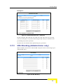
URL Blocking (Administrator only).....................................................................65
3.7.4
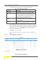
Domain Filter (Administrator only) .....................................................................67
3.7.5
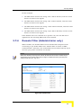
Firewall (Administrator only) ..............................................................................69
3.7.6
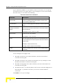
Miscellaneous Items (Administrator only)..........................................................70
NG System Manual
x
Introducing the Networking Gateway IDU
3.8
3.9
NAT Setting (Administrator only) ..................................................................72
3.8.1
Virtual Server .....................................................................................................72
3.8.2
Special AP..........................................................................................................74
3.8.3
DMZ Host ...........................................................................................................75
3.8.4
VPN Pass Through ............................................................................................76
Advanced Settings (Administrator only) ......................................................78
3.9.1
System Time ......................................................................................................78
3.9.2
System Log ........................................................................................................79
3.9.3
Dynamic DNS.....................................................................................................81
3.9.4
SNMP Setting.....................................................................................................82
3.9.5
Routing Table.....................................................................................................84
3.9.6
Schedule Rule....................................................................................................86
3.9.7
UPnP Setting......................................................................................................90
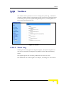
3.10 Toolbox ............................................................................................................91
3.10.1 View Log ............................................................................................................91
3.10.2 Firmware Upgrade (Administrator only).............................................................92
3.10.3 Backup Setting ...................................................................................................93
3.10.4 Reset to Default .................................................................................................94
3.10.5 Reboot................................................................................................................95
3.10.6 DRAP .................................................................................................................95
3.10.7 Miscellaneous Items ..........................................................................................96
3.11 Web Configuration Server’s Parameters Summary.....................................98
Appendix A - Print Server .............................................................. 111
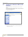
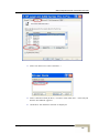
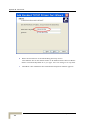
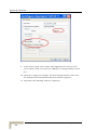
A.1
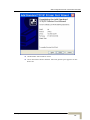
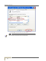
Configuring on Windows 2000 and XP Platforms......................................112
Glossary......................................................................................... 119
NG System Manual
xi
Figures
Figure 1: Front Panel .........................................................................................................................11
Figure 2: Rear Panel (without antenna).............................................................................................13
Figure 3: Log In Window....................................................................................................................23
Figure 4: Networking Gateway Main Window....................................................................................24
Figure 5: System Status ....................................................................................................................26
Figure 6: Setup Wizard ......................................................................................................................28
Figure 7: Setup Wizard - Select WAN Type ......................................................................................28
Figure 8: Setup Wizard – WAN Type - Static IP Address..................................................................29
Figure 9: Setup Wizard - Dynamic IP Address ..................................................................................30
Figure 10: Setup Wizard - Dynamic IP Address with Road Runner Session Management ..............31
Figure 11: Setup Wizard – PPP over Ethernet ..................................................................................32
Figure 12: Setup Wizard – PPTP.......................................................................................................33
Figure 13: Setup Wizard - Configuration Completed.........................................................................35
Figure 14: Basic Setting.....................................................................................................................36
Figure 15: WAN Setup/Primary Setup ...............................................................................................36
Figure 16: Virtual Computers.............................................................................................................37
Figure 17: Choose WAN Type...........................................................................................................38
Figure 18: Primary Setup - Static IP Address....................................................................................39
Figure 19: Primary Setup - Dynamic IP Address...............................................................................40
Figure 20: Primary Setup - Dynamic IP Address with Road Runner Session Management.............41
Figure 21: Primary Setup - PPPoE ....................................................................................................43
Figure 22: Primary Setup - PPTP ......................................................................................................45
Figure 23: LAN Setup ........................................................................................................................46
Figure 24: LAN Setup - DHCP Server Enabled.................................................................................48
Figures
Figure 25: DHCP Clients List.............................................................................................................49
Figure 26: MAC Address Control.......................................................................................................50
Figure 27: DHCP Clients Combo Box ...............................................................................................52
Figure 28: Wireless Setting ...............................................................................................................52
Figure 29: Wireless Clients List .........................................................................................................54
Figure 30: Advanced Wireless Setting ..............................................................................................55
Figure 31: Change Password ............................................................................................................58
Figure 32: Security Setting Window ..................................................................................................59
Figure 33: Packet Filter Initial Window ..............................................................................................61
Figure 34: Inbound Packet Filter – Example 1 ..................................................................................63
Figure 35: Inbound Packet Filter - Example 2 ...................................................................................63
Figure 36: Outbound Packet Filter - Example 1 ................................................................................64
Figure 37: Outbound Packet Filter - Example 2 ................................................................................65
Figure 38: URL Blocking....................................................................................................................65
Figure 39: URL Blocking Example.....................................................................................................66
Figure 40: Domain Filter ....................................................................................................................67
Figure 41: Firewall .............................................................................................................................69
Figure 42: Miscellaneous Items.........................................................................................................70
Figure 43: NAT Setting ......................................................................................................................72
Figure 44: Virtual Server....................................................................................................................73
Figure 45: Special Applications .........................................................................................................75
Figure 46: DMZ Host .........................................................................................................................76
Figure 47: VPN Pass Through...........................................................................................................76
Figure 48: Advanced Setting .............................................................................................................78
Figure 49: System Time ....................................................................................................................78
Figure 50: System Log ......................................................................................................................80
Figure 51: Dynamic DNS...................................................................................................................81
Figure 52: SNMP Setting...................................................................................................................83
Figure 53: Routing Table ...................................................................................................................84
NG System Manual
xiv
Introducing the Networking Gateway IDU
Figure 54: Schedule Rule ..................................................................................................................86
Figure 55: Schedule rule Setting .......................................................................................................87
Figure 56: Schedule Rule Setting – Example Step 1 ........................................................................88
Figure 57: Schedule Rule Setting – Example Step 2 ........................................................................88
Figure 58: Virtual Server - Schedule Rule#1 .....................................................................................89
Figure 59: Packet Filter - Schedule Rule#1.......................................................................................89
Figure 60: UPnP Setting ....................................................................................................................90
Figure 61: Toolbox .............................................................................................................................91
Figure 62: View System Log..............................................................................................................92
Figure 63: Firmware Upgrade............................................................................................................93
Figure 64: Backup..............................................................................................................................94
Figure 65: Reset to Default................................................................................................................94
Figure 66: Reboot ..............................................................................................................................95
Figure 67: DRAP Protocol .................................................................................................................95
Figure 68: Toolbox - Miscellaneous Items.........................................................................................97
NG System Manual
xv
Tables
Table 1: Radio Specifications ..............................................................................................................6
Table 2: Regulatory Standards Compliance........................................................................................6
Table 3: Environmental Specifications.................................................................................................7
Table 4: Mechanical Specifications .....................................................................................................7
Table 5: Electrical Specifications .........................................................................................................7
Table 6: Front Panel LEDs ................................................................................................................11
Table 7: Rear Panel Connectors .......................................................................................................13
Table 8: Status Window Parameters .................................................................................................26
Table 9: Setup Wizard – Static IP Address Parameters....................................................................30
Table 10: Setup Wizard – Dynamic IP Address Parameters.............................................................31
Table 11: Setup Wizard – Dynamic IP Address with Road Runner Session Management
Parameters ........................................................................................................................................32
Table 12: Setup Wizard – PPPoE Parameters..................................................................................33
Table 13: Setup Wizard – PPTP Parameters ....................................................................................34
Table 14: Virtual Computers Parameters ..........................................................................................37
Table 15: Static IP Address Parameters ...........................................................................................39
Table 16: Dynamic IP Address Parameters ......................................................................................41
Table 17: Dynamic IP Address with Road Runner Session Management Parameters ....................42
Table 18: PPP over Ethernet Parameters .........................................................................................43
Table 19: PPTP Parameters..............................................................................................................45
Table 20: LAN Setup Parameters......................................................................................................47
Table 21: DHCP Clients List Parameters ..........................................................................................49
Table 22: DHCP Clients List Parameters ..........................................................................................50
Table 23: Wireless Setting Parameters .............................................................................................53
Tables
Table 24: Wireless Clients List Parameters ......................................................................................55
Table 25: Advanced Wireless Setting Parameters............................................................................56
Table 26: Advanced Wireless Setting Parameters............................................................................61
Table 27: URL Blocking Parameters .................................................................................................66
Table 28: Domain Filter Parameters..................................................................................................68
Table 29: Firewall Parameters...........................................................................................................69
Table 30: Miscellaneous Items Parameters ......................................................................................70
Table 31: Virtual Server Parameters .................................................................................................73
Table 32: Special Applications Parameters.......................................................................................75
Table 33: VPN Pass Through Parameters ........................................................................................77
Table 34: System Time Parameters ..................................................................................................79
Table 35: System Log Parameters ....................................................................................................80
Table 36: Dynamic DNS Parameters ................................................................................................82
Table 37: SNMP Parameters.............................................................................................................83
Table 38: Routing Table Parameters.................................................................................................85
Table 39: Scheduling Table Parameters ...........................................................................................87
Table 40: DRAP Protocol Parameters...............................................................................................96
Table 41: Miscellaneous Items Parameters ......................................................................................97
Table 42: Web Configuration Server’s Parameters Summary ..........................................................98
NG System Manual
xviii
1
Chapter 1 - Product Description
In This Chapter:
Introducing the Networking Gateway IDU, page 2
Functions and Features, page 3
Specifications, page 6
Chapter 1 - Product Description
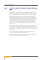
1.1
Introducing the Networking Gateway
IDU
Alvarion's Networking Gateway Indoor Unit (IDU) enables operators and
service providers using Alvarion’s Broadband Wireless Access system to
provide subscribers with a number of broadband services transparently.
The Networking Gateway IDU together with the SU-ODU comprises a
Subscriber Unit that provides data connections to the Base Station. The
four 10/100Base-T Ethernet ports connect to the user’s data equipment,
providing comprehensive routing functionality and supporting various
security features. User’s data equipment equipped with either IEEE
802.11b (11M) or IEEE 802.11g (54M) compatible wireless adapters can
connect to the unit via its built-in Wireless LAN port, functioning as an
Access Point.
The Networking Gateway IDU is powered from the mains. The Networking
Gateway IDU is connected to the ODU via a category 5E Ethernet cable.
This cable carries the Ethernet data between the two units as well as power
(54 VDC) and control signals to the ODU. It also carries status indications
from the ODU.
The Networking Gateway is designed for remote management and
supervision using the built-in internal web server.
The Networking Gateway is easily updated and upgraded as it supports
remote software and configuration file download.
Product Description
2
Functions and Features
1.2
Functions and Features
1.2.1
Basic Functions
Auto-sensing Ethernet Switch
Equipped with a 4-port auto-sensing Ethernet switch.
Printer sharing
Embedded print server to allow all of the networked computers to share
one printer through the USB host port.
WAN Types
Support of several WAN types: Static, Dynamic, PPPoE, PPTP, and
Dynamic IP with Road Runner Session Management (e.g., Telstra,
BigPond).
Firewall
All unwanted packets from outside intruders can be blocked to protect
the Intranet.
DHCP Server Support
All of the networked computers can retrieve TCP/IP settings
automatically from the Networking Gateway.
Web-based configuring
Configurable through any networked computer’s web browser.
Virtual Server Support
Enables to expose WWW, FTP and other services on your LAN to other
Internet users.
User-Definable Application Sensing Tunnel
Users can define the attributes to support special applications requiring
multiple connections, such as Internet gaming, video conferencing,
Internet telephony and so on. The Networking Gateway can sense the
application type port as a trigger and open a multi-port tunnel for it.
DMZ Host Support
Allows one specific networked computer to be fully exposed to the
Internet. This function is used when special application sensing tunnel
feature is insufficient to allow an application to function correctly. Use
with caution.
NG System Manual
3
Chapter 1 - Product Description
Statistics of WAN Support
Enables to monitor inbound and outbound packets.
1.2.2
Wireless Functions
High speed for wireless LAN connection
Up to 54 Mbps data rate by incorporating Orthogonal Frequency
Division Multiplexing (OFDM).
IEEE 802.11b compatible (11M)
Allowing inter-operation among multiple vendors.
IEEE 802.11g compatible (54M)
Allowing inter-operation among multiple vendors.
Auto fallback
54M, 48M, 36M, 24M, 18M, 12M, 6M data rates with auto fallback in
802.11g mode.
11M, 5.5M, 2M, 1M data rates with auto fallback in 802.11b mode.
1.2.3
Security Functions
Packet Filter
Packet Filter allows controlling access to a network by analyzing the
incoming and outgoing packets and letting them pass or blocking them
based on the source and destination IP addresses and ports.
Domain Filter Support
Enables preventing users from accessing specific domains by disabling
the DNS resolution.
URL Blocking Support
URL Blocking uses keywords to block hundreds of applicable websites
connections.
VPN Pass-through
The Networking Gateway can also support VPN pass-through.
802.1X Support
When the 802.1X function is enabled, the Wireless user must be
authenticated by the Networking Gateway before being allowed to use
the Network services.
Product Description
4
Functions and Features
SPI Mode Support
When SPI Mode is enabled, the Networking Gateway checks every
incoming packet and detects if this packet has changed its IP address
since initial negotiation.
DoS Attack Detection Support
When this feature is enabled, the Networking Gateway detects and logs
Denial of Service (DoS) attack arriving from the Internet.
1.2.4
Advanced Functions
System Time
Allows synchronizing system time with a network time server, with the
PC, or set the time manually.
E-mail Alert
The Networking Gateway can be configured to send its log file by mail.
Dynamic DNS
At present, the Networking Gateway supports 3 Dynamic DNSs:
DynDNS.org, TZO.com and dhs.org.
Routing Table
The Networking Gateway supports static routing and two kinds of
dynamic routing: RIP1 and RIP2.
Schedule Rule
Customers can control the schedule (when to allow and when to block)
for several functions, such as virtual server and packet filters.
NG System Manual
5
Chapter 1 - Product Description
1.3
Specifications
1.3.1
Radio Specifications
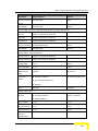
Table 1: Radio Specifications
Item
Description
Frequency
2400-2483.5 MHz
Wireless LAN Standards
Compliant with IEEE 802.11b and IEEE 802.11g
Output Power
10, 12, 15, 17 dBm
Data Rates
IEEE 802.11g mode: 54M, 48M, 36M, 24M, 18M, 12M, 6M
with auto fallback in.
IEEE 802.11b mode: 11M, 5.5M, 2M, 1M with auto fallback
in.
1.3.2
Regulatory Standards Compliance
Table 2: Regulatory Standards Compliance
Type
Standard
EMC
ETS EN 301 489-17
Safety
EN 60950 (CE)
IEC 60 950 US/C UL
Radio
ETSI 300 328
FCC Part 15
Immunity
EN 55024:1998
Product Description
6
Specifications
1.3.3
Environmental
Table 3: Environmental Specifications
Item
Details
Operating temperature
0 o C to 40 o C
Operating humidity
5%-95% non condensing
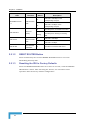
1.3.4
Mechanical
Table 4: Mechanical Specifications
Item
Details
Dimensions (W x H x D)
190.5 x 26.2 x 111 mm
Weight
0.62 kg
1.3.5
Electrical
Table 5: Electrical Specifications
Item
Details
Power Transformer
100-240 VAC, 50-60 Hz, 2A max.
Supplies 5 VDC (for the Networking Gateway IDU) and 55 VDC (for
the ODU via the RADIO connector)
Power Consumption
Networking Gateway IDU (5 VDC): 10W max
ODU (55 VDC): 50W max.
NG System Manual
7
2
Chapter 2 - Installation
In This Chapter:
Installation Requirements, page 10
Panels Layout and Components, page 11
Installation and Commissioning, page 14
Chapter 2 - Installation
2.1
Installation Requirements
2.1.1
Packing List
Networking Gateway IDU
Antenna
Power Transformer
Mains power cord
2.1.2
Additional Installation Requirements
Ethernet cable(s) for connecting to the end-user’s data equipment.
Mains plug adapter or termination plug (if the power plug on the
supplied AC power cord does not fit local power outlets).
PC with an Ethernet card and an Ethernet cable for configuring the
Networking Gateway IDU parameters using a web browser, and for
configuring the SU-ODU parameters using Telnet.
Other installation tools and materials (e.g., means for securing cables to
walls, etc.)
Installation
10
Panels Layout and Components
2.2
Panels Layout and Components
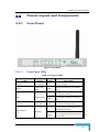
2.2.1
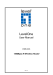
Front Panel
Figure 1: Front Panel
2.2.1.1
Front Panel LEDs
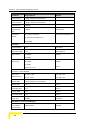
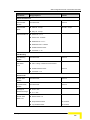
Table 6: Front Panel LEDs
LED
POWER
WLAN
Function
Status
Power Indication On
Power is available.
Wireless LAN
Sending or receiving data via wireless
Activity
Blinking
On
USB
USB Port Activity
Blinking
STATUS
System Status
Blinking
On
LAN LINK/ACT
1~4
Description
LAN.
The USB port is linked.
The USB port is sending or receiving
data.
The unit is functioning properly.
An active station is connected to the
corresponding LAN port.
LAN Status
Blinking
The corresponding LAN port is sending or
receiving data.
NG System Manual
11
Chapter 2 - Installation
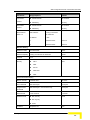
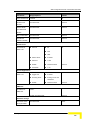
LED
Function
Status
On
LAN SPEED 10/100
LAN Port Data
1~4
Rate
Off
On
ODU LINK/ACT
ODU 10/100
2.2.1.2
Data rate is 100 Mbps on the
corresponding LAN port.
Data rate is 10 Mbps on the
corresponding LAN port.
The ODU port is connected to the ODU.
ODU Port
Activity
ODU Port Data
Rate
ODU WLINK
Description
ODU Wireless
Link Status
Blinking
The ODU port is sending or receiving
data.
On
Data rate is 100 Mbps.
Off
Data rate is 10 Mbps.
On
The ODU is connected with an AU.
RESET ROUTER Button
Press momentarily the recessed RESET ROUTER button to reset the
Networking Gateway IDU.
2.2.1.3
Resetting the IDU to Factory Defaults
Press the RESET ROUTER button for at least 5 seconds, until the STATUS
LED flashes 5 times. After releasing the button, the unit will resume
operation with the factory default configuration.
Installation
12
Panels Layout and Components
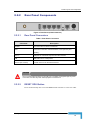
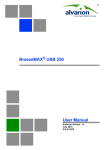
2.2.2
Rear Panel Components
Figure 2: Rear Panel (without antenna)
2.2.2.1
Rear Panel Connectors
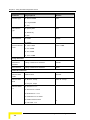
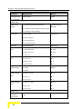
Table 7: Rear Panel Connectors
Connector
Description
POWER
DC Power Inlet from Power Transformer
ODU
Connection to the ODU. Carries Ethernet, Power (55 VDC) and
signaling.
Port 1-4
LAN ports for networked computers and other devices.
USB
USB Host Port for a USB printer.
Antenna (not marked)
An SMA connector for the WLAN antenna
CAUTION
Do not connect data equipment to the ODU port. The ODU port supplies high DC power
to the ODU, and this may harm other equipment connected to it.
2.2.2.2
RESET ODU Button
Press momentarily the recessed RESET ODU button to reset the ODU.
NG System Manual
13
Chapter 2 - Installation
2.3
Installation and Commissioning
The unit can be placed on a desktop or a shelf. Alternatively, it may be wallmounted.
For optimal performance, place the Networking Gateway in the center of
your office (or your home), in a location that is away from any potential
source of interference, such as a metal wall or microwave oven. This
location must be close to a mains outlet and network connections.
It is assumed that the SU-ODU is already installed, and that the IDU-ODU
cable is connected to it.
To install the Networking Gateway IDU:
1
Assemble an RJ-45 connector with a protective cover on the indoor end
of the IDU-ODU cable. The length of the IDU-ODU straight cable should
not exceed 100m. Refer to the relevant System Manual for instructions
on preparing the cable and for information on the cable type.
2
Connect the IDU-ODU cable to the ODU connector located on the rear
panel.
3
Connect the power cord of the transformer to the unit’s POWER socket,
located on the rear panel. Connect the Mains power cord to the power
transformer and to the AC mains.
NOTE
The color codes of the power cable are as follows:
Brown
Phase
~
Blue
Neutral
0
Yellow/Green
Ground
4
When power is connected, the unit will automatically enter the self-test
phase. When it is in the self-test phase, the STATUS LED will be lit ON
for about 10 seconds, and will then blink 3 times, indicating that the
self-test operation has ended. Finally, the STATUS LED will blink
continuously one blink per second, indicating that the unit is
functioning properly.
5
Connect a PC with a DHCP Client to one of the LAN ports using a Pinto-Pin Ethernet cable.
Installation
14
Installation and Commissioning
NOTE
It is assumed that the Networking Gateway is in the factory default configuration. If
necessary, press the RESET ROUTER button for at least 5 seconds, until the STATUS
LED flashes 5 times. After releasing the button, the unit will resume operation with the
factory default configuration.
6
Connection to the Web Configuration Server is done using a web
browser with the address http://192.168.1.1 (the default LAN IP
address). If the Web Configuration Server is password protected, you will
be prompted to enter the password in order to login (the default
password is installer). Refer to Chapter 3 for more details on using the
Web Configuration Server.
7
To enable access to the Monitor Program of a BreezeACCESS VL
SU-ODU:
a
Open a web browser and connect to the Networking Gateway using
the default LAN IP address (192.168.1.1).
b
Configure the WAN IP Address of the Networking Gateway to a static
IP address that is different than that of the SU-ODU and belongs to
the subnet (e.g., use 10.0.0.2 for the default IP address, which is
10.0.0.1 with subnet mask 255.255.255.0).
c
Reboot the Networking Gateway for the new settings to take effect.
8
Using Telnet from the computer, connect to the SU-ODU’s Monitor
program using the SU-ODU’s IP address, and configure its basic
parameters according to instructions supplied by the system
administrator. Align the antenna of the SU-ODU for optimal
performance. Refer to the Commissioning section of the relevant System
Manual for details on configuration of basic parameters and antenna
alignment.
9
Open the web browser and connect to the Gateway using the default
LAN IP address (192.168.1.1).
10 Configure the necessary parameters according to instructions supplied
by the system administrator. The mandatory parameters that must be
configured properly are:
When using DRAP, enable DRAP and set DRAP Server Port to 8171
(no need to define the DRAP server IP address).
WAN Type and Static IP address parameters including WAN Gateway
and DNS (if Static IP Address is selected in WAN Type).
LAN IP Address (LAN and WAN must belong to different subnets).
NG System Manual
15
Chapter 2 - Installation
To enable remote management via the WAN, enable Remote
Administrator Host and specify the IP address (or range) of the
remote management station(s), or 0.0.0.0 for any IP. For
management through AlvariSTAR, verify that the Remote
Administrator Port is configured to 8080.
11 Reboot the Gateway for the new settings to take effect.
12 If a printer is to be used, connect it to the USB port using a standard
USB cable. To configure the Print Server on your computer(s), refer to
Appendix A - Print Server.
13 Configure the network settings of the data equipment for proper
operation with the Networking Gateway according to the configured LAN
Setup parameters.
14 To verify data connectivity, from the end-user’s PC or from a portable
PC connected to the unit, try to connect to the Internet.
15 Verify proper operation using the LED indicators (see Table 6).
Installation
16
Notes on Using the Networking Gateway in Alvarion’s Systems
2.4
Notes on Using the Networking
Gateway in Alvarion’s Systems
2.4.1
Notes on Using Networking Gateways in a
BreezeMAX System (Version 1.5 and
higher)
The Monitor program of the SU-ODU uses the fixed IP address
192.168.254.251 with the subnet mask 255.255.255.0. To access the
Monitor program of the SU-ODU from the LAN port of the Gateway, the
WAN port must be configured to static IP address that belongs to the
same subnet (e.g. 192.168.254.253, which is the default). The LAN IP
Address must be configured to a different subnet (e.g. 192.168.1.1/24,
which is the default). It is recommended to enable DHCP Server on the
LAN and use a PC with a DHCP Client (defaults).
Information about the Gateways using DRAP that are connected to each
SU can be viewed in the Base Station’s Monitor program (in the
Voice/Networking Gateways option of the Configuration menu for a
selected SU). The displayed information includes Gateway’s type and IP
Address (VLANs are not supported by the Networking Gateway).
Provision an L2 Service. Note that the Networking Gateway does not
support VLANs.
2.4.2
Notes on Using Networking Gateways in a
BreezeACCESSVL System
To access the Monitor program of the SU-ODU from the LAN port of the
Gateway, the WAN port must be configured to static IP address that belongs
to the subnet as the SU-ODU (the default for ODU is 10.0.0.1 with subnet
mask 255.255.255.0). The LAN IP Address must be configured to a
different subnet (e.g. 192.168.1.1/24, which is the default). It is
recommended to enable DHCP Server on the LAN (enabled by default), and
use a PC with a DHCP Client.
2.4.3
Notes on Using AlvariSTAR for Remote
Management of Networking Gateways
To enable remote management via the WAN, enable Remote Administrator
Host and specify the IP address (or subnet) of the remote management
station(s). Verify that the Remote Administrator Port is configured to 8080.
NG System Manual
17
3
Chapter 3 - Using the Web Configuration
Server
In This Chapter:
Start-up and Log in on page 20
Status on page 26
Wizard on page 28
Basic Setting on page 36
Security Setting on page 59
NAT Setting on page 72
Advanced Settings on page 78
Toolbox on page 91
Chapter 3 - Using the Web Configuration Server
3.1
Introduction
The Networking Gateway IDU can be configured using the following
methods:
Using a web browser to access the built-in Web Configuration Server
Using TFTP to load a backup configuration file from a PC with a TFTP
Client connected to a LAN port (the unit includes a TFTP Server). For
more details see section 3.10.3.
This document describes the configuration using the Web Configuration
Server.
Using the Web Configuration Server
20
Accessing the Web Configuration Server
3.2
Accessing the Web Configuration
Server
NOTE
Access to the Web Configuration Server from the LAN has precedence over access from
the WAN. If a user is connected to the Web Configuration Server from the LAN, it is not
possible to access it from the WAN. Also, connecting to the Web Configuration Server
from the LAN will disconnect all open connections from the WAN.
3.2.1
Remote Connection via the WAN
It is assumed that Remote Administrator Host is enabled and that the IP
address of the station you use is included in the Remote Administrator Host
IP address range. It is also assumed that the Remote Administrator Port is
configured to 8080. You must also have prior knowledge of the WAN IP
Address of the unit.
Follow the steps below to access the Web Configuration Server:
1
Open a web browser.
NOTE
Be sure to disable the proxy on your Web browser or add the IP address of the product
into the proxy exceptions.
2
Enter http://<WAN IP Address>:8080 in the appropriate field of the
browser and click Enter.
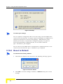
3.2.2
3
If the Web Configuration Server is password protected, you will be
prompted to enter your password in order to login to the system. The
default password is installer.
4
The Web Configuration Server main view appears on the screen.
Local Connection via the LAN
You must have prior knowledge of the LAN IP Address and Mask as well as
the DHCP Server/DHCP Proxy settings. Otherwise, you may need to reset
the unit to its Factory default configuration (see section 2.2.1.3)
1
Connect a PC to one of the LAN ports using an Ethernet cable.
2
If the LAN is configured as either a DHCP Server or a DHCP Proxy, it is
recommended to use a PC with a DHCP Client. Otherwise, the PC
should be configured to an IP address that belongs to the same subnet
as the LAN e.g., 192.168.1.2, and the Default Gateway Address must be
the LAN IP Address e.g., 192.168.1.1.
NG System Manual
21
Chapter 3 - Using the Web Configuration Server
3
Open a web browser.
NOTE
Be sure to disable the proxy on your Web browser or add the IP address of the product
into the proxy exceptions.
4
Enter http://<LAN IP Address> in the Address (Internet Explorer) or
Location (Netscape) field of the browser and click Enter.
5
If the Web Configuration Server is password protected, you will be
prompted to enter your password in order to login to the system. The
default password is installer.
6
The Web Configuration Server main view appears on the screen.
Using the Web Configuration Server
22
Log in and Log out
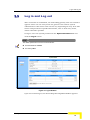
3.3
Log in and Log out
After connection is established, the networking gateway web user interface
appears. There are two entry levels: for general users and for system
administrators. The menus and screens vary depending on entry level. The
menus and parameters specified hereinafter, refer to both entry levels,
unless otherwise specified.
To log in, enter the system password in the System Password field and
click the Log in button.
NOTE
The default passwords for the two access levels are:
For Administrators: installer
For Users: public
Figure 3: Log In Window
Upon successful Log in, the Networking Gateway Main Window appears.
NG System Manual
23
Chapter 3 - Using the Web Configuration Server
Figure 4: Networking Gateway Main Window
3.3.1
The Main Menu
The Web Configuration Server view consists of a number of menu links (to
the left). Clicking on each of them expands the menu node and displays the
selected page with the applicable content (configurable parameters/options
or status information) in the main area.
IMPORTANT
Many pages include a "Save" button. Click on the Save button before selecting another
page/menu item, or before quitting the application. The Save functionality in many cases is per
page. If you leave the page without clicking the Save button, all the changes in the page will be
discarded.
Changes to most of the settings are applied only after restarting the unit
(refer to section 3.10.5).
3.3.2
Control Buttons
A control button causes an immediate action. To activate a control button,
click on it. Certain control buttons only appear in selected windows. Others
are common to most windows.
NOTE
Some control buttons may be disabled for user entry level (public password).
Using the Web Configuration Server
24
Log in and Log out
Save – Saves any changes made to the configuration. Most changes
require rebooting the system for them to take effect.
Undo – Recovers the original settings.
Help – Displays a help screen for the specific window.
Refresh – Refreshes the displayed information.
Back – Reverts to a previous step/screen.
<<Previous – In windows that are divided into several pages, use the
<<Previous button to jump to the previous page.
Next>> - In windows that are divided into several pages, use the Next>>
button to jump to the next page.
Cancel – Clears unsaved changes to the configuration.
Reboot – Reboots the Networking Gateway.
NG System Manual
25
Chapter 3 - Using the Web Configuration Server
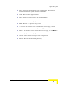
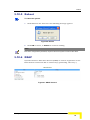
3.4
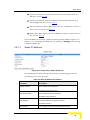
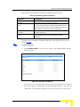
Status
The Status window appears in the main window upon successful log in. The
window can be accessed at any time by clicking on the Status menu on the
menu list.
Figure 5: System Status
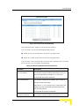
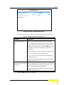
The Status window provides information for observing the product's working
status, as follows:
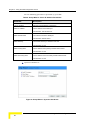
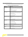
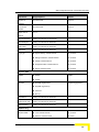
Table 8: Status Window Parameters
Parameter
Description
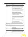
Remaining Lease Time
A counter displaying the remaining time (in hh:mm:ss) in
which unit will request a new IP. When the lease time expires,
a new IP address will be automatically allocated, or the lease
will be automatically renewed, depending on the settings (see
sections 3.6.1.2 and 3.6.1.3.
This field is relevant only for Dynamic IP Address mode and
will not appear in any of the other modes.
Renew (Administrator only) – In Dynamic IP Address
mode, click to reset the Lease Time. The gateway will
request an IP address from the DHCP server.
In Static IP Address, PPPoE and PPTP modes, the WAN
type is specified in the sidenote (Static IP, PPPoE, or
PPTP, respectively).
Using the Web Configuration Server
26
Status
Parameter
Description
IP Address
The WAN IP address.
Release (Administrator only) – In Dynamic IP Address
mode only, Click to release the WAN IP address.
Subnet Mask
The Subnet mask of the device. (The default is
255.255.255.0)
Gateway
The default Gateway IP address.
Domain Name Server
The DNS Server IP address(es).
Connection Time (PPPoE
Connect/ Disconnect – When in PPPoE or PPTP mode, click
and PPTP modes only)
Connect to initiate a session, or Disconnect to terminate a
session.
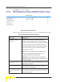
Peripheral Status
The USB Printer status:
Not ready - no printer is available
Off-line or No Paper – the printer is off-line or the paper
tray is empty
Printing – the printer is currently printing
Ready - a printer is connected and ready to print.
Device error – a general error occurred.
Traffic Statistics
Enables to monitor inbound and outbound packets for WAN,
LAN and wireless beginning from last reset.
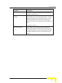
In addition, the Status window includes the following buttons:
View Log – opens the log file for viewing. See section 3.10.1.
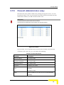
Clients List – opens the list of DHCP assigned clients. See section
3.6.2.1.
NG System Manual
27
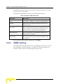
Chapter 3 - Using the Web Configuration Server
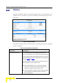
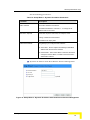
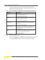
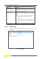
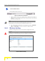
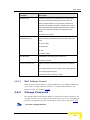
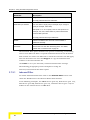
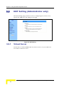
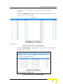
3.5
Wizard (Administrator only)
The Setup Wizard will guide you through the basic configuration procedure
(recommended for most users).
Figure 6: Setup Wizard
1
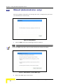
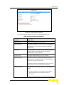
Click on Next. The Select WAN Type window appears.
NOTE
You can click Back at any time to return to previous screens and change your settings.
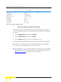
Figure 7: Setup Wizard - Select WAN Type
2
Select the WAN Type from the list:
Using the Web Configuration Server
28
Wizard (Administrator only)
Static IP Address – a static IP Address provided by the ISP
Dynamic IP Address – an IP Address automatically obtained from the
ISP (default)
Dynamic IP Address with Road Runner Session Management (e.g.
Telstra, BigPond)
PPP over Ethernet – some ISPs require the use of PPPoE to connect
to their services
PPTP – Some ISPs require the use of PPTP to connect to their
services.
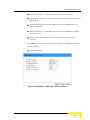
3
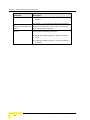
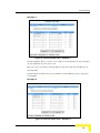
Click Next. For each WAN type selected, a different WAN Type-specific
window appears:
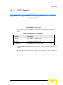
Static IP Address
Figure 8: Setup Wizard – WAN Type - Static IP Address
NG System Manual
29
Chapter 3 - Using the Web Configuration Server
Set the following parameters provided by your ISP:
Table 9: Setup Wizard – Static IP Address Parameters
Parameter
Description
LAN IP Address
Sets the local IP address of the device.
Static IP Address
The IP address of the WAN port.
The default is 192.168.254.253.
Static Subnet Mask
The subnet mask of the WAN port.
The default is 255.255.255.0.
Static Gateway
The Default Gateway IP address of the unit.
The default is 0.0.0.0.
Static Primary DNS
The IP address of the primary Domain Name Server.
The default is 0.0.0.0.
Static Secondary DNS
The IP address of the secondary Domain Name Server.
The default is 0.0.0.0.
Dynamic IP Address
Figure 9: Setup Wizard - Dynamic IP Address
Using the Web Configuration Server
30
Wizard (Administrator only)
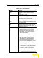
Set the following parameters:
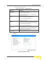
Table 10: Setup Wizard – Dynamic IP Address Parameters
Parameter
Description
LAN IP Address
The local IP address of the device.
The default IP address is 192.168.1.1. To change the IP
address enter a new value.
Host Name: Optional
Some ISPs require a host name, for example, Home.
A string of maximum 39 characters.
The default is an empty field.
WAN's MAC Address
The gateway's pre-configured MAC Address.
Clone MAC - Click to replace the Gateway's WAN MAC
Address with the PC's MAC Address.
Restore MAC - When Clone MAC is activated, the button
changes to Restore MAC, to enable to restore the unit's
default MAC Address.
Dynamic IP Address with Road Runner Session Management
Figure 10: Setup Wizard - Dynamic IP Address with Road Runner Session Management
NG System Manual
31
Chapter 3 - Using the Web Configuration Server
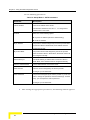
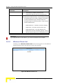
Set the following parameters:
Table 11: Setup Wizard – Dynamic IP Address with Road Runner Session Management
Parameters
Parameter
Description
LAN IP Address
The local IP address of the device.
The default IP address is 192.168.1.1. To change the IP
address enter a new value.
Account
The account provided by the service provider. If you do not
want to change the account, leave empty. At initial entry, you
are required to enter an account.
A string of up to 53 printable characters.
The default is an empty field.
Password
The password provided by the service provider. If you do not
want to change the password, leave empty. At initial entry,
you are required to enter a password.
A string of up to 53 printable characters.
Login Server
The Login Server (optional). Leave empty if you want the
default server.
PPP over Ethernet
Figure 11: Setup Wizard – PPP over Ethernet
Using the Web Configuration Server
32
Wizard (Administrator only)
Set the following parameters:
Table 12: Setup Wizard – PPPoE Parameters
Parameter
Description
LAN IP Address
The local IP address of the device.
The default IP address is 192.168.1.1. To change the IP
address enter a new value.
Account
The account provided by the service provider.
A string of up to 53 printable characters.
The default is an empty field.
Password
The password provided by the service provider. If you do not
want to change the password, leave empty. At initial entry,
you are required to enter a password.
A string of up to 53 printable characters.
Primary DNS
The DNS provided by your ISP. To use a specific DNS, enter
a specific address. Leave the default 0.0.0.0 setting to
automatically assign the parameter.
Secondary DNS
The backup DNS provided by the service provider. (optional)
PPTP
Figure 12: Setup Wizard – PPTP
NG System Manual
33
Chapter 3 - Using the Web Configuration Server
Set the following parameters:
Table 13: Setup Wizard – PPTP Parameters
Parameter
Description
LAN IP Address
The local IP address of the device.
The default IP address is 192.168.1.1. . To change the IP
address enter a new value.
IP Mode
select one of the following options:
Dynamic IP Address (this is the default setting)
Static IP Address
My IP Address
The private IP address assigned by the service provider after
connection. When in Static Mode, the IP address must be
configured manually.
My Subnet Mask
The private subnet mask assigned by the service provider
after connection. When in Static Mode, the subnet mask must
be configured manually.
WAN Gateway IP
The WAN Gateway IP address after connection. When in
Static Mode, the IP address must be configured manually.
Server IP Address/Name
The IP address/Name of the PPTP server.
PPTP Account
The user account assigned by the service provider.
A string of up to 53 characters
PPTP Password
The password assigned by the service provider. If you do not
want to change the password, leave this field empty. At initial
entry, you are required to enter a password.
A string of up to 53 characters
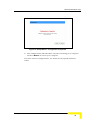
4
After setting the appropriate parameters, the following window appears:
Using the Web Configuration Server
34
Wizard (Administrator only)
Figure 13: Setup Wizard - Configuration Completed
5
The configurations will take effect only after rebooting your computer.
Click on Reboot to restart your computer.
For more advance configurations, see details on the specific windows,
below.
NG System Manual
35
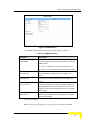
Chapter 3 - Using the Web Configuration Server
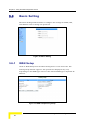
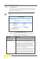
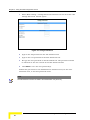
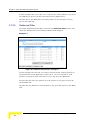
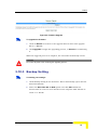
3.6
Basic Setting
The Basic Setting window allows to configure the settings for WAN, LAN,
and Wireless and to change the password.
Figure 14: Basic Setting
3.6.1
WAN Setup
Click on WAN Setup from the Basic Setting menu on the menu list. The
Primary Setup window appears. The parameters displayed may vary
depending on the WAN Type selected. The default WAN Type is Dynamic IP
Address.
Figure 15: WAN Setup/Primary Setup
Using the Web Configuration Server
36
Basic Setting
NOTE
The WAN setup window is read only for user level entry.
From the WAN Setup window you can:
Set the WAN type – allows to select the WAN connection type of your
ISP.
NAT – Enable/Disable - When disabled, the gateway functions as a
regular router as opposed to a NAT router. This option is available in the
Primary Setup window for all WAN types. The default setting is Enabled.
Set Virtual Computers (Administrators only) – Enabled when using NAT.
In addition to the primary WAN address, enables to set up one-to-one
mapping of up to five global IP address and local IP address (see Figure
16 below).
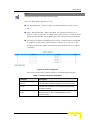
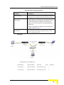
Figure 16: Virtual Computers
The Virtual Computers window includes the following parameters:
Table 14: Virtual Computers Parameters
Parameter
Description
Global IP
Enter the global IP address assigned by the service provider.
Local IP
Enter the local IP address of your LAN PC corresponding to
the global IP address.
Enable
Check/Uncheck this item to enable/disable the Virtual
Computer feature.
NG System Manual
37
Chapter 3 - Using the Web Configuration Server
NOTE
The Reboot button is not available at first entry to the Primary Setup window and appears
only after saving your changes.
For user entry level (public password), the parameter fields in all WAN type screens are
disabled (for display only).
IMPORTANT
Changes to the Primary Setup window will take effect only after rebooting the system.
The default WAN type is Dynamic IP Address. However, you can change
the WAN type as follows:
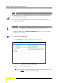
To select a different WAN type:
1
Click Change. The Choose WAN Type window opens.
Figure 17: Choose WAN Type
2
Select one of the following types:
Static IP Address: The ISP provides you with a static IP address. See
section 3.6.1.1. This is the default setting.
Using the Web Configuration Server
38
Basic Setting
Dynamic IP Address: Automatically obtain an IP address from the
ISP. See section 3.6.1.2.
Dynamic IP Address with Road Runner Session Management (e.g.
Telstra BigPond). See section 3.6.1.3.
PPP over Ethernet: Some ISPs require the use of PPPoE to connect to
their services. See section 3.6.1.4.
PPTP: Some ISPs require the use of PPTP to connect to their services.
See section 3.6.1.5.
For each WAN type selected, a different Primary Setup window appears, as
follows. You can change the WAN type by clicking on Change and selecting
a different WAN type.
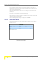
3.6.1.1
Static IP Address
Figure 18: Primary Setup - Static IP Address
The Setup page for Static IP Address includes the following parameters
provided by the service provider:
Table 15: Static IP Address Parameters
Parameter
Description
WAN IP Address
The IP address of the WAN port.
The default is 192.168.254.253.
WAN Subnet Mask
The IP subnet mask of the WAN port.
The default is 255.255.255.0
WAN Gateway
The Default Gateway IP address of the unit.
The default is 0.0.0.0.
Primary DNS
The IP address of the primary Domain Name Server.
NG System Manual
39
Chapter 3 - Using the Web Configuration Server
Parameter
Description
The default is 0.0.0.0.
Secondary DNS
The IP address of the secondary Domain Name Server.
The default is 0.0.0.0.
NAT
Enable/Disable. When disabled, the gateway functions as a
regular router as opposed to a NAT router. This option is
available in the Primary Setup window for all WAN types.
The default is: Enable
3.6.1.2
Dynamic IP Address
Figure 19: Primary Setup - Dynamic IP Address
Using the Web Configuration Server
40
Basic Setting
The Setup page for Dynamic IP Address includes the following parameters:
Table 16: Dynamic IP Address Parameters
Parameter
Description
Host Name
Optional - Some ISPs require a host name, for example,
Home.
A string of maximum 39 characters.
WAN's MAC Address
The gateway's pre-configured MAC Address.
Clone MAC - Click to replace the Gateway's WAN MAC
Address with the PC's MAC Address.
Restore MAC - When Clone MAC is activated, the button
changes to Restore MAC, to enable to restore the unit's
pre-configured MAC Address.
Renew IP Forever
When enabled, this feature will automatically renew your IP
address when the lease time expires, even if the system is
idle.
NAT
Enable/Disable - When disabled, the gateway functions as a
regular router as opposed to a NAT router.
The default is: Enable
3.6.1.3
Dynamic IP Address with Road Runner Session
Management
Figure 20: Primary Setup - Dynamic IP Address with Road Runner Session Management
NG System Manual
41
Chapter 3 - Using the Web Configuration Server
The Setup page for Dynamic IP Address with Road Runner Session
Management provides authentication using dedicated DHCP server and
includes the following parameters:
Table 17: Dynamic IP Address with Road Runner Session Management Parameters
Parameter
Description
Account
The account provided by your ISP
A string of maximum 53 characters.
Password
The password provided by your ISP. If you do not want to
change the password, leave empty.
A string of maximum 53 characters.
Login Server
The Login Server (optional). Leave empty if you want the
default server.
A string of maximum 31 characters.
Renew IP Forever
Enable/Disable – when enabled, your IP address will
automatically be renewed when the lease time expires, even
if the system is idle.
NAT
Enable/Disable - When disabled, the gateway functions as a
regular router as opposed to a NAT router.
The default is: Enable
3.6.1.4
PPP over Ethernet
Some ISPs require the use of PPPoE to connect to their services. If this is
the case, click Change to select PPPoE as your WAN type. The Primary
Setup window display changes to reflect the parameters for PPPoE.
Using the Web Configuration Server
42
Basic Setting
Figure 21: Primary Setup - PPPoE
The Setup page for PPPoE includes the following parameters:
Table 18: PPP over Ethernet Parameters
Parameter
Description
PPPoE Account
The account assigned to you by your ISP.
PPPoE Password
The password assigned to you by your ISP. This field always
appears blank. If you don't want to change the password,
leave it empty.
Primary DNS
The DNS provided by your ISP. To use a specific DNS, enter
a specific address. Leave the default 0.0.0.0 setting to
automatically assign the parameter.
Secondary DNS
Maximum Idle Time
The backup DNS provided by your ISP. (optional)
The amount of time of inactivity before disconnecting your
PPPoE session. To disable this feature, set this parameter to
0 seconds, or enable Auto-reconnect.
The Maximum Idle Time is applicable only when Connection
Control is set to Connect-on-demand or to Manually.
Connection Control
Authentication for IP allocation. Select one of the following
options:
Connect-on-demand – An IP address is automatically
allocated whenever the user attempts to make a
connection.
Auto reconnect(Always-on) – The system automatically
NG System Manual
43
Chapter 3 - Using the Web Configuration Server
Parameter
Description
connects to the ISP after restart or after connection is
dropped.
Manually – The user manually performs the connection.
Maximum Transmission Unit
Most ISPs provide an MTU value to users. The maximum
(MTU)
MTU value allowed is 1492 bytes.
More >>
Click to display the following parameters:
PPPoE Service Name (optional) - Directs to a PPPoE
server.
Assigned IP Address (optional) – The fixed IP assigned
by the ISP.
Using the Web Configuration Server
44
Basic Setting
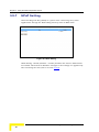
3.6.1.5
PPTP
Some ISPs require the use of PPTP to connect to their services.
Figure 22: Primary Setup - PPTP
The Setup page for PPTP includes the following parameters:
Table 19: PPTP Parameters
Parameter
Description
IP Mode
Select one of the following options:
Dynamic IP Address (this is the default setting)
Static IP Address
My IP Address
The private IP address assigned by your ISP. This parameter
is enabled only for Static IP Address mode.
My Subnet Mask
The private subnet mask assigned by your ISP. This
parameter is enabled only for Static IP Address mode.
WAN Gateway IP
The WAN Gateway IP address. This parameter is enabled
only for Static IP Address mode.
Address/Name
The IP address/Name of the PPTP server.
PPTP Account
The user account assigned by your ISP.
A string of maximum 53 characters.
Connection ID
Enter the connection ID if your ISP requires it (optional).
NG System Manual
45
Chapter 3 - Using the Web Configuration Server
Parameter
Description
Maximum Idle Time
The amount of time of inactivity before disconnecting your
PPTP session. To disable this feature, set this parameter to 0
seconds, or enable Auto-reconnect.
Connection Control
Authentication for IP allocation. Select one of the following
options:
Connect-on-demand – An IP address is automatically
allocated whenever the user attempts to make a
connection.
Auto reconnect(Always-on) – The system automatically
connects to the ISP after restart or after connection is
dropped.
Manually – The user manually performs the connection.
3.6.2
LAN Setup
Select Basic Setting > LAN Setup submenu on the menu list. The LAN Setup
window opens.
Figure 23: LAN Setup
Using the Web Configuration Server
46
Basic Setting
The LAN Setup page includes the following parameters:
Table 20: LAN Setup Parameters
Parameter
Description
LAN IP Address
Sets the local IP address of the device. The users on your
network must use this LAN IP address as their default
gateway. You can change it as necessary.
The default is: 192.168.1.1
LAN Subnet Mask
Sets the subnet mask to the LAN IP address.
DHCP Server
Enable/Disable to turn off this service. When enabled, the
LAN Setup window display changes (indicated by the red
icon), and the following parameters are displayed (see Figure
24):
Range of IP addresses Pool – Specify the starting and
ending address for DHCP clients. The IP addresses are
allocated from this pool according to calculations based
on the client’s MAC address.
Domain suffix – Specify the domain suffix for DHCP
clients.
Primary DNS – Specify the primary DNS for DHCP
clients.
Secondary DNS – Specify the secondary DNS for DHCP
clients.
Primary WINS – Specify the primary WINS address for
DHCP clients.
Secondary WINS – Specify the secondary WINS address
for DHCP clients.
Lease Time – The time set (in minutes) for IP allocation.
Changes to the settings are applied only after rebooting the
unit (refer to Section 3.10.5).
DHCP Proxy
This parameter is available only when DHCP Server is
disabled.
NG System Manual
47
Chapter 3 - Using the Web Configuration Server
Figure 24: LAN Setup - DHCP Server Enabled
The LAN PC receives a DHCP IP address from the Networking Gateway. To
receive the DHCP IP address from the DHCP server, perform the following
procedure:
3
Set the DHCP Server parameter to Disable.
4
Set the DHCP Proxy parameter to Enable.
5
In the Proxy IP field, enter the IP of the DHCP server.
In addition, the LAN Setup window includes the following control buttons:
Clients List – Opens a list of the current mapping of the IP and MAC
address for each DHCP client (see section 3.6.2.1)
Fixed Mapping – Opens the MAC Address Control window for assigning a
specific IP address to the specified MAC address for DHCP clients (see
MAC Address Control on page 56 for further details).
Using the Web Configuration Server
48
Basic Setting
3.6.2.1
DHCP Clients List
Figure 25: DHCP Clients List
The DHCP Clients List displays the following parameters for each DHCP
client:
Table 21: DHCP Clients List Parameters
Parameter
Description
IP Address
The IP address of the DHCP client.
Host Name
The host name of the DHCP client.
MAC Address
The MAC address of the DHCP client.
From the DHCP Clients List window you can do the following for the selected
clients:
Wake up – Sends Ethernet packets to turn on the PC, relevant hardware
and configuration is required on NIC and PC
Delete – Delete the selected clients from the list.
NG System Manual
49
Chapter 3 - Using the Web Configuration Server
3.6.2.2
Fixed Mapping
Opens the MAC Address Control window. MAC Address Control allows to
assign different access rights for different users and to assign a fixed IP
address to a specific MAC address.
NOTE
All the settings in this page will take effect only when MAC Address Control is set to
"Enable".
Figure 26: MAC Address Control
The MAC Address Control window includes the following parameters:
Table 22: DHCP Clients List Parameters
Parameter
Description
MAC Address Control
Check "Enable" to enable the MAC Address Control feature.
Connection control
Check the "Connection control" check box to enable
controlling which wired and wireless clients can connect to
this device. If a client is denied the connection to this device,
he will not be able to access the Internet either. Select
allow/deny to allow or deny clients whose MAC addresses
are not in the "Control table" (see below) to connect to this
device. ("deny" is the default setting.)
A wired client who is allowed to connect to the device has full
access to the Internet and to network resources. When
denied the connection to the device, he can communicate
with other clients on the wired LAN, but cannot connect to the
Internet, use the Print Server function, communicate with
Using the Web Configuration Server
50
Basic Setting
Parameter
Description
clients on the wireless LAN, or use the Web configuration.
Association control
"Association" refers to the exchanging of information between
wireless clients and the device to establish a link between
them. A wireless client is able to transmit and receive data to
the device only after successful association. Check
"Association control" check box to control which wireless
clients can associate to the wireless LAN. If a client is denied
the association to the wireless LAN, he will not be able to
send or receive any data via this device. Select allow/deny to
allow or deny clients whose MAC addresses are not in the
"Control table" to associate to the wireless LAN.
A wireless client who is allowed both to associate to the
wireless LAN and to connect to the device has full access to
the Internet and to network resources.
When allowed to associate to the wireless LAN, but denied to
connect to the device, he can communicate with other clients
on the LAN (wired and wireless), but cannot connect to the
Internet, use the Print Server function, or use the Web
configuration.
When denied to associate to the wireless LAN, the client
cannot communicate with other clients on the LAN (wired or
wireless), connect to the internet, use the Print Server
function, or use the Web configuration.
NOTE: Association control does not affect wired clients.
Control Table: Each row in the control table indicates the MAC address and the mapped IP
address of a single client.
MAC Address
The MAC address of a specific client.
IP Address
The expected IP address of the corresponding client. Leave
empty if you do not want to specify an IP address for the
corresponding client.
C
When "Connection control" is checked, checking "C" will
allow/deny (depending on the connection control setting) the
corresponding client to connect to this device.
A
When "Association control" is checked, checking "A" will
allow/deny (depending on the association control setting) the
corresponding client to associate to the wireless LAN.
NG System Manual
51
Chapter 3 - Using the Web Configuration Server
To enter the MAC address:
Use the DHCP clients combo box.
Figure 27: DHCP Clients Combo Box
1
Select a specific client in the "DHCP clients" Combo box and click on
Copy to to copy the MAC address of the selected client to the selected
ID in the "ID" Combo box
NOTE
When the unit has a list of clients connected through DHCP, and the unit is reset, the list
will show empty. In this case renew the PC IP address from DHCP on LAN.
2
The control table is divided into several pages. Use the << Previous
page and Next Page >> buttons to jump to a different page.
3.6.3
Wireless Setting
Wireless settings allow you to set the wireless configuration items.
CAUTION
Changing any of the parameters may cause loss of wireless link connectivity to the unit
if the settings do not match the settings on the WLL subscriber in the User's PC.
Figure 28: Wireless Setting
Using the Web Configuration Server
52
Basic Setting
The Wireless Setting window includes the following parameters:
Table 23: Wireless Setting Parameters
Parameter
Description
Wireless
Enable/Disable – Check the Enable box to enable this
service.
The default setting is "Enable".
Network ID (SSID)
Network ID is used for identifying the Wireless LAN (WLAN).
Client stations can roam freely over this product and other
Access Points that have the same Network ID.
The factory setting is "default".
Channel
The radio channel number. The permissible channels depend
on the Regulatory Domain.
Security
Select the data privacy algorithm you want to protect your
data when being transferred from one station to another. The
available security protocols are:
None – No encryption is applied. (default)
WEP (Wired Equivalent Privacy) – Encrypts frames
transmitted through a wireless module using a preentered WEP key. You can configure 4 key sets and
select one to apply as follows:
−
WEP 64 bit - 10 hexadecimal digits
−
WEP 128 bit – 26 hexadecimal digits
802.1x – When enabled, the wireless user must be
authenticated before it is allowed to use the network
services. One implementation of 802.1x (the most
common one) is through a RADIUS server on your LAN,
containing an authentication database.
−
Encryption Key Length – Select either 64 or 128 bits
for the encryption key.
−
RADIUS Server IP – The 802.1x server's IP address.
−
RADIUS Port – The 802.1x server's service port.
WPA-PSK - Accepts WPA clients only. Manually enter a
pre-share key (encryption key) as follows:
−
Pre-share key mode: ASCII or HEX can be selected.
NG System Manual
53
Chapter 3 - Using the Web Configuration Server
Parameter
Description
−
Pre share key: 32 ASCII characters or 64
hexadecimal digits pre-share key (encryption key).
WPA (Wi-Fi Protected Access) – improves data protection
and implements access control to Wireless LAN systems.
Frames transmitted through a wireless module are
encrypted using a Pre-share key (PSK) or a key received
from the RADIUS server.
−
RADIUS Server IP – The 802.1x server's IP address.
−
RADIUS Port – The 802.1x server's service port.
−
RADIUS Shared Key – Key value shared by the
RADIUS server and the networking gateway. The key
value is consistent with the one in the RADIUS server.
IMPORTANT
If you enable the 802.1x or WPA feature, you must have a RADIUS server available.
3.6.3.1
Wireless Clients List
Clicking on the Wireless Clients List button that appears in the Wireless
Setting window opens the Wireless Clients List window.
Figure 29: Wireless Clients List
Using the Web Configuration Server
54
Basic Setting
The Wireless Clients List displays the following parameters for each wireless
client:
Table 24: Wireless Clients List Parameters
Parameter
Description
Connected Time
The connection time.
MAC Address
The MAC address of the wireless client.
3.6.3.2
Advanced Wireless Setting
Clicking the Advanced Wireless Setting button that appears in the
Wireless Setting window opens the Advanced Wireless Setting window.
Figure 30: Advanced Wireless Setting
NG System Manual
55
Chapter 3 - Using the Web Configuration Server
The Advanced Wireless Setting window includes the following parameters:
Table 25: Advanced Wireless Setting Parameters
Parameter
Description
Beacon Interval
Specify the intervals (in milliseconds) between the packets
sent by the access point to synchronize the wireless network
(beacons).
The range is 1~65535 milliseconds
The default is 100 milliseconds.
RTS Threshold
Specify the packet size above which a Request To Send will
be performed. Used to determine whether CSMA/CD or
CSMA/CA will be used.
The range is 256~2432 bytes
The default is 2432 bytes.
Fragmentation Threshold
Specify the packet size above which fragmentation will be
performed.
The range is 256~2346 bytes, even numbers only
The default is 2346 bytes.
DTIM Interval
Delivery Traffic Indication Message (DTIM) is a countdown
informing clients of the next window for listening to broadcast
and multicast messages.
The range is: 1~255 seconds.
The default value is 3 seconds.
Wireless Mode
The wireless mode supported: 802.11b, 802.11g, or mixed.
The default is mixed.
TX Rates
Select the wireless transfer rate from the dropdown list,
based on the speed of wireless adapters on the WLAN.
The default is auto rate.
Using the Web Configuration Server
56
Basic Setting
Parameter
Description
Preamble Type
Defines the length of the Cyclic Redundancy Check (CRC)
block for communication between the Access Point and
roaming wireless adapters. A long transmit preamble may
provide a more reliable connection or slightly longer range. A
short transmit preamble provides better performance. Select
short/long or automatic preamble to be assigned to each
packet.
The default is auto mode.
Authentication Type
Used for wireless authentication when associated with an AP
router.
Open System
Shared Key
Both
The default is Both.
SSID Broadcast
Enable/Disable broadcasting the network's ID.
The default is Enable.
Antenna Transmit Power
Select the antenna's transmission power from the dropdown
list.
The average wireless mini PCI output power is approximately
15 including supplied antenna.
The default is 100% TX power (17 dBm).
3.6.3.3
MAC Address Control
MAC Address Control allows to assign different access rights for different
users and to assign a fixed IP address to a specific MAC address. For
further details, see section 3.6.2.2.
3.6.4
Change Password
The Change Password window allows to change the system password. For
security reasons, it is strongly recommended that you do so. Changing the
password is applied only after rebooting the unit (refer to Section 3.10.5)
To access change password:
NG System Manual
57
Chapter 3 - Using the Web Configuration Server
1
Select Basic Setting > Change Password submenu on the menu list. The
Change Password window opens.
Figure 31: Change Password
2
Type in the old password in the Old Password box.
3
Type in the new password in the New Password box.
4
Re-type the new password in the Reconfirm box. The password should
be identical to the one entered in the New Password field.
5
Click Save to save the new password(s).
Follow this procedure for the Administrator Password level, for the User
Password level, or for both password levels.
NOTE
The Administrator Password is visible to the Administrator entry level only.
Using the Web Configuration Server
58
Security Setting
3.7
Security Setting
Click on the Security Setting menu on the menu list to display the
submenus and the Security Setting window.
Figure 32: Security Setting Window
3.7.1
MAC Control
MAC Address Control allows to assign different access rights for different
users and to assign a fixed IP address to a specific MAC address. For
further details, see section 3.6.2.2.
3.7.2
Packet Filters (Administrator only)
IMPORTANT
packet filters only works with NAT enabled.
Packet Filter enables to control which packets are allowed to pass through
the networking gateway. When selecting the Packet Filters submenu on the
menu list, the Outbound Packet Filter window opens. To create
inbound/outbound filter rules, note that the NG will first perform
mask/un-mask of the NAT process and later check the rules.
NOTE
The Inbound Filter… button at the bottom of the window toggles between the
Outbound and Inbound Packet Filter windows. The button's text will change from
Inbound Filter… to Outbound Filter… accordingly.
NG System Manual
59
Chapter 3 - Using the Web Configuration Server
Changes to the settings are applied only after rebooting the unit (refer to
section 3.10.5).
Using the Web Configuration Server
60
Security Setting
Figure 33: Packet Filter Initial Window
The Outbound filter applies on all outbound packets.
You can select one of the following filtering policies:
Allow all to pass except those match the specified rules
Deny all to pass except those match the specified rules
Up to 8 rules can be specified for each direction, inbound and outbound.
For each rule, you can define the following:
Table 26: Advanced Wireless Setting Parameters
Parameter
Description
Source IP address
You can define a single IP address (for example, 4.3.2.1) or a
range of IP addresses (for example, 4.3.2.1-4.3.2.254).
An empty field denotes all IP addresses.
Source Ports address
You can define a single port (for example, 80) or a range of
ports (for example, 1000-1999).
Add a prefix "T" or "U" to specify a TCP or UDP protocol. For
example, T80, U53, U2000-2999. No prefix indicates both
TCP and UDP protocols.
An empty field denotes all port addresses.
Destination IP address
You can define a single IP address (for example, 4.3.2.1) or a
NG System Manual
61
Chapter 3 - Using the Web Configuration Server
Parameter
Description
range of IP addresses (for example, 4.3.2.1-4.3.2.254).
An empty field denotes all IP addresses.
Destination port address
You can define a single port (for example, 80) or a range of
ports (for example, 1000-1999).
Add prefix "T" or "U" to specify a TCP or UDP protocol. For
example, T80, U53, U2000-2999. No prefix indicates both
TCP and UDP protocols.
An empty field denotes all port addresses.
Enable
Check to enable the rule. Each rule can be enabled or
disabled individually.
Use Rule#
Packet Filter can work with Scheduling Rules. For details,
please refer to Schedule Rule on page 86.
The Schedule Rule option facilitates the process of selecting a scheduling
rule for each Filter ID. Select a specific Schedule Rule from the Schedule
Rule Combo box. Select the Filter ID to which the schedule rule will apply
from the ID Combo box and click Copy to to copy the Schedule Rule
number to the selected Filter ID.
Click Save to save your Inbound/Outbound Packet Filter settings.
The following paragraphs provide examples for using the
Inbound/Outbound Packet Filter option.
3.7.2.1
Inbound Filter
To enable Inbound Packet Filter click on the Inbound Filter button and
check the Enable box in the Inbound Packet Filter window.
In the following examples, the SMTP Server (port 25), POP Server (port 110),
Web Server (port 80), FTP Server (port 21), and News Server (port 119) are
defined in the Virtual Server or DMZ Host.
Using the Web Configuration Server
62
Security Setting
Example 1:
Figure 34: Inbound Packet Filter – Example 1
In this example, IPs (1.2.3.100-1.2.3.149) can send packets to any machine
on the LAN side to ports 25 to 110.
IPs (1.2.3.10-1.2.3.20) to send packets to any port and any IP address on
the LAN side.
Packets from all other IPs to any machine on the LAN side and to any port
are blocked.
Example 2:
Figure 35: Inbound Packet Filter - Example 2
NG System Manual
63
Chapter 3 - Using the Web Configuration Server
In this example, IPs [1.2.3.100-1.2.3.119] can not send packets to any IP on
the LAN side to ports 119 (for read news) and 21 (FTP service).
All other IPs on the WAN side can send packets to any machine and any
port on the LAN side.
3.7.2.2
Outbound Filter
To enable Outbound Packet Filter, click on the Outbound Filter button and
check the Enable box in the Outbound Packet Filter window.
Example 1:
Figure 36: Outbound Packet Filter - Example 1
In this example, IP (192.168.123.149) is restricted from sending packets to
any IP address on the WAN side to ports 25 to 110. It is allowed to send
packets to any ports other than 25 to 110 to any IP on the WAN side
IP (192.168.123.20) is not allowed to send packets to any port and any IP
on the WAN side.
All other IPs are allowed to send packets to any port and any IP on the WAN
side.
Using the Web Configuration Server
64
Security Setting
Example 2:
Figure 37: Outbound Packet Filter - Example 2
In this example, IPs (192.168.123.100) and (192.168.123.119) can only
read net news (port 119) and send mail (port 25). They are blocked from
performing any other operation.
All other IPs are blocked from performing any operation.
3.7.3
URL Blocking (Administrator only)
When enabled, this feature blocks LAN computers from connecting to predefined Web sites.
Figure 38: URL Blocking
NG System Manual
65
Chapter 3 - Using the Web Configuration Server
The URL Blocking window includes the following parameters:
Table 27: URL Blocking Parameters
Parameter
Description
URL Blocking
Enable/Disable - Check to enable the URL Blocking feature.
URL
If any part of the Web site's URL matches the pre-defined
word specified in this field, the connection will be blocked.
For example, you can use a pre-defined word "sex" to block
all Web sites whose URLs contain the word "sex".
Enable
Check to enable the rule. Each rule can be enabled or
disabled individually.
Use Rule#
URL Blocking can work with Scheduling Rules. For details,
please refer to Schedule Rule on page 86.
The Schedule Rule option facilitates the process of selecting a scheduling
rule for each Filter ID. Select a specific Schedule Rule from the Schedule
Rule Combo box. Select the Filter ID to which the schedule rule will apply
from the ID Combo box and click Copy to to copy the Schedule Rule
number to the selected Filter ID.
Click Save to save your settings.
The following section provides an example for using the URL Blocking
option.
3.7.3.1
URL Blocking - Example
Figure 39: URL Blocking Example
Using the Web Configuration Server
66
Security Setting
In this example:
1
All URLs which include the string "msn" will be blocked, and the action
will be recorded in the log file.
2
All URLs which include the string "sina" will be blocked, and the action
will be recorded in the log file.
3
All URLs which include the string "cnnsi" will be blocked, and the action
will be recorded in the log file.
4
All URLs which include the string "espn" will be blocked, and the action
will be recorded in the log file.
If the Enable box is not checked for a specific rule, the rule will not be
applied and the matching URLs will not be blocked.
3.7.4
Domain Filter (Administrator only)
When enabled, the Domain Filter feature blocks LAN computers from
connecting to pre-defined Web sites. Domain filter is based on DNS
resolution filter. Therefore, the domain filter feature will work only if you
execute query name resolution via the NG.
NOTE
While URL Blocking uses keywords to block all Web sites whose URL includes the prespecified keyword, Domain Filter blocks a single or multiple domains by specifying the
suffix (such as xxx.com, .org, etc.).
Figure 40: Domain Filter
NG System Manual
67
Chapter 3 - Using the Web Configuration Server
Up to 9 Domain Suffixes can be defined, and for each rule you can specify
the desired action to be taken when a user attempts to access that domain.
For each rule you can define the following:
Table 28: Domain Filter Parameters
Parameter
Description
Domain Filter
Check to enable the Domain Filter feature to prevent users
from accessing specific URLs.
Log DNS Query
Check to enable logging users' attempts to enter the specified
URLs.
Privilege IP Addresses
Sets a group of hosts and allows them to access the network
Range
without restriction.
The range is: From: 1~254, To: 1~254
Domain Suffix
A suffix of URL to be restricted.
For example, ".com", "xxx.com".
Action
You can specify the type of action you want performed when
someone attempts to access the specific URL that meets the
domain-suffix:
Drop – Check to block access.
Log – Check to log the access attempt.
Enable
Check to enable the rule. Each rule can be enabled/disabled
individually.
In the example above (Figure 40):
1
The URL "www.msn.com" will be blocked, and the action will be
recorded in the log file.
2
The URL "www.sina.com" will not be blocked, but any attempt to enter
the Web site will be recorded in the log file.
3
The URL "www.google.com" will be blocked, but the action will not be
recorded in the log file.
4
IP address X.X.X.1~ X.X.X.20 (where X.X.X is the network configured on
the LAN side - by default 192.168.1) can access network without
restriction.
Click Save to save your settings.
Using the Web Configuration Server
68
Security Setting
3.7.5
Firewall (Administrator only)
Firewall rules deny/allow traffic from passing through the device. In case
firewall and filter rules are provisioned, NG will check the firewall rule first.
If firewall is allowed, the NG checks the filter rule.
IMPORTANT
Firewall will work only with the NAT feature enabled.
Inbound/outbound packet filter works property only with NAT enabled.
Figure 41: Firewall
Up to 8 rules can be specified for each direction of traffic: inbound and
outbound. For each rule, you can define the following:
Table 29: Firewall Parameters
Parameter
Description
Source IP address
From LAN or WAN
Destination IP address
From LAN or WAN
Destination Protocol
TCP, UDP or ICMP
Destination
Destination port number
Action
Allow/Deny
The default is Allow
Enable
Check to enable the rule. Each rule can be enabled/disabled
individually
NG System Manual
69
Chapter 3 - Using the Web Configuration Server
Click Save to save your settings.
3.7.6
Miscellaneous Items (Administrator only)
Figure 42: Miscellaneous Items
From the Miscellaneous Items window you can set the following parameters:
Table 30: Miscellaneous Items Parameters
Parameter
Description
Remote Administrator
Enables the user to perform administration tasks from a
Host/Port
remote host. When enabled, only the specified IP address
can perform remote administration. If the specified IP address
is 0.0.0.0, any host can connect to this device in order to
perform administration tasks. You can use subnet mask bits
"/nn" notation to specify a group of trusted IP addresses.
For example, "10.1.2.0/24".
NOTE - When Remote Administration is enabled, the web
server port will automatically change to 8080. You can
change the web server port to another port.
IMPORTANT – When managing the NG via AlvariSTAR
(using the cut through option), the Remote Administrator Port
must be set to 8080.
Administrator Time-out
The time of no activity to logout automatically. Set it to zero to
disable automatic time-out
TFTP Access Client/Port
When enabled, the specified IP address can access the
device using a TFTP client utility.
Discard PING from WAN
side
When enabled, any ping packet from WAN will be discarded.
The default is: Uncheck
Using the Web Configuration Server
70
Security Setting
Parameter
Description
Changes to the settings are applied only after rebooting the
unit (refer to Section 3.10.5).
SPI Mode
When enabled, the router records the information, such as IP
address, port address, ACK, SEQ number and so on, of the
packets that pass through the WAN, and the Networking
Gateway checks every incoming packet to detect whether it is
valid.
The default is: Uncheck
DoS Attack Detection
When enabled, the router detects and logs the Denial of
Service (DoS) attack that comes from the Internet. Currently,
the Networking Gateway can detect the following DoS attack:
SYN Attack, WinNuke, Port Scan, Ping of Death, and Land
Attack etc.
NG System Manual
71
Chapter 3 - Using the Web Configuration Server
3.8
NAT Setting (Administrator only)
The NAT Setting page provides access to configuring the virtual server,
special AP, DMZ host and VPN pass through.
Figure 43: NAT Setting
3.8.1
Virtual Server
Virtual Server enables WWW, FTP and other services on your LAN to be
accessible to Internet users.
Using the Web Configuration Server
72
NAT Setting (Administrator only)
Figure 44: Virtual Server
Specify the following parameters for each ID:
Table 31: Virtual Server Parameters
Parameter
Description
Protocol
Select from TCP, UDP, * (all).
The default setting is *.
Service Ports
Enter a port number, or a range of ports.
Server IP
Enter the server IP on the LAN interface.
The range is 1~254.
Enable
Check to enable the rule. Each rule can be enabled/disabled
individually.
Use Rule#
Virtual Server can work with Scheduling Rules. For details,
please refer to Schedule Rule on page 86.
In addition, the Virtual Server page allows to easily select services from a
pre-defined list, and to assign to them a pre-defined rule.
Well known services – Select a service from the list of pre-defined
services.
NG System Manual
73
Chapter 3 - Using the Web Configuration Server
The Schedule Rule option facilitates the process of selecting a
scheduling rule for each Virtual Server ID. Select a specific Schedule
Rule from the Schedule Rule Combo box. Select the Virtual Server ID to
which the schedule rule will apply from the ID Combo box and click
Copy to to copy the Schedule Rule number to the selected Virtual
Server ID.
3.8.2
Special AP
Some applications, such as Internet games, Video conferencing, Internet
telephony etc., require multiple connections. Because of the firewall
function, these applications cannot work with a pure NAT router. The
Special Applications window makes some of these applications work with
NAT router.
NOTE
Only one PC at a time can use each Special Application.
Using the Web Configuration Server
74
NAT Setting (Administrator only)
Figure 45: Special Applications
The Special Applications window includes the following parameters:
Table 32: Special Applications Parameters
Parameter
Trigger
Description
The outbound destination port number issued by the
application.
Incoming Ports
When the trigger packet is detected using the destination
port, the inbound packets to the specified port numbers are
allowed to pass through the networking gateway. If no
packets arrive for 1 minute, the ports will close.
Enable
Check to enable the rule. Each rule can be enabled/disabled
individually.
Some predefined settings are provided. Select an application from the predefined list, select the ID number (1-10) and click Copy to, to add the
predefined setting to your list.
NOTE
If Special Applications fails to make an application work, try DMZ host instead.
3.8.3
DMZ Host
Demilitarized Zone (DMZ) Host is a host without the firewall protection. It
allows a computer to be exposed to unrestricted 2-way communication for
NG System Manual
75
Chapter 3 - Using the Web Configuration Server
Internet games, Video conferencing, Internet telephony (H.323 or SIP), and
other special applications.
CAUTION
This feature exposes your computer and may cause security issues. Make sure your PC is
updated with the last security updates.
Figure 46: DMZ Host
Check the Enable box to enable this feature. One IP address should be set
on the subnet of LAN. Changes to the settings are applied only after
rebooting the unit (refer to Section 3.10.5)
3.8.4
VPN Pass Through
Figure 47: VPN Pass Through
Using the Web Configuration Server
76
NAT Setting (Administrator only)
The VPN Pass Through window includes the following parameters:
Table 33: VPN Pass Through Parameters
Parameter
Description
VPN PPTP Pass-Through
Check to enable PPTP connection to pass through the
device. The device can handle up to 8 concurrent sessions.
The default is: Check
VPN IPSec Pass-Through
Check to enable IPSec connection to pass through the
device. The device can handle up to 16 concurrent sessions.
The default is: Check
NG System Manual
77
Chapter 3 - Using the Web Configuration Server
3.9
Advanced Settings (Administrator
only)
The Advanced Settings menu provides access to configuring additional
features, such as System Time, Log, Dynamic DNS, SNMP, Routing,
Scheduling Rules and enabling Universal Plug and Play protocol.
Figure 48: Advanced Setting
3.9.1
System Time
The System Time window enables to set the device time. Changes to the
settings are applied only after rebooting the unit (refer to Section 3.10.5)
Figure 49: System Time
Using the Web Configuration Server
78
Advanced Settings (Administrator only)
From the System Time window, you can select one of the following ways to
set the date and time of the device:
Table 34: System Time Parameters
Parameter
Description
Get Date and Time by NTP
Select if you want to set the device's internal clock using the
Protocol
Network Time Protocol (NTP) from a specific server located
on the internet.
Time Server - Select an NTP time server to consult UTC
time.
Time Zone - Select a time zone where this device is
located.
Sync Now! - Synchronize system time with network time
server (alternatively, synchronization will be performed
automatically from every 10 hours).
Set Date and Time using
Select if you want the device's internal clock to synchronize
PC's Date and Time
with the PC's clock.
Set Date and Time manually
Select if you want to manually set the device's internal clock.
You need to specify:
Date: Year, Month, Day
Time: Hours (0-23), Minutes (0-59), Seconds (0-59).
The clock is set upon clicking Save.
NOTE
The device time is displayed at the bottom of the Status window.
In addition, you can specify daylight saving time as follows:
Daylight Saving - Enable/disable Daylight Saving and set start and end
time of daylight saving time range.
3.9.2
System Log
System Log enables to set parameters for exporting system logs to a
specified destination. Two exporting methods are supported: syslog (UDP)
and SMTP (TCP).
An e-mail alert will be sent in one of the following conditions:
NG System Manual
79
Chapter 3 - Using the Web Configuration Server
If the size of the log file is up to 12 Kbytes, an e-mail alert is sent every
1 hour.
When the size of the log file reaches 12 Kbytes, an e-mail alert is sent
immediately.
Figure 50: System Log
The System Log window includes the following parameters:
Table 35: System Log Parameters
Parameter
IP Address for Syslog Server
Description
Enter the IP address of the syslog server. It is valid only on
your subnet LAN. Check to Enable this function.
E-mail Alert Enable
Check if you want to enable Email alert (send syslog via
email).
SMTP Server IP and Port - Enter the SMTP server IP and
port, which are concatenate with ':'.For example,
"mail.your_url.com" or "192.168.1.100:26". If you do not
specify port number, the default value is 25.
E-mail addresses - The listed recipients will receive these
logs. You can assign more than 1 recipient, using a semicolon (;) or a comma (,) to separate the addresses.
E-mail Subject - The subject of email alert. This setting is
optional.
Username and Password - To fill some SMTP server's
Using the Web Configuration Server
80
Advanced Settings (Administrator only)
Parameter
Description
authentication requirement, you may need to enter the
Username and Password provided by your ISP.
Log Type
Select the activities to be logged.
NOTE
The changes made in the System Log page become effective upon clicking Save.
Rebooting the system is not required.
To view the system log:
Click on the View Log… button at the bottom of the screen. The System Log
opens (see View Log on page 91, Figure 62)
3.9.3
Dynamic DNS
To host your server on a changing IP address, you need to use a Dynamic
Domain Name Service (DDNS).
To reach your host, one needs to know its name. Dynamic DNS will map
the name of your host to your current IP address, which changes each time
you connect to your Internet service provider.
Figure 51: Dynamic DNS
Before enabling Dynamic DNS, you need to register an account on of the
Dynamic DNS servers listed here under Provider: DnyDNS.org(Dynamic),
NG System Manual
81
Chapter 3 - Using the Web Configuration Server
DnyDNS.org(Custom), TZO.com and dhs.org. Upon registration, you will
receive your account details.
The Dynamic DNS window includes the following parameters:
Table 36: Dynamic DNS Parameters
Parameter
Description
DDNS
Click Enable or Disable to enable/disable Dynamic DNS.
Provider
Select from the list of Dynamic DNS servers on which you
have an account.
Host Name
Enter to register a domain name to the DDNS provider. The
full domain name is concatenated with the specified Host
Name and a suffix, specified by the DDNS provider.
Username/E-mail
Enter your Username or E-mail address according to the
DDNS provider you selected.
Password/Key
Enter your password or key according to the DDNS provider
you selected.
After Dynamic DNS setting is configured, click Save.
3.9.4
SNMP Setting
The Simple Network Management Protocol (SNMP) provides the user with
the capability to remotely manage a computer network by polling and
setting terminal values and monitoring network events.
Using the Web Configuration Server
82
Advanced Settings (Administrator only)
Figure 52: SNMP Setting
The SNMP Setting window includes the following parameters:
Table 37: SNMP Parameters
Parameter
Description
Enable SNMP
You must check either Local or Remote or both to enable the
SNMP function.
Local - The device will respond to requests from LAN.
Remote – The device will respond to requests from WAN.
Get Community
Set the password for GetRequest access rights to your
device.
Set Community
Setting the password for SetRequest access rights to your
device.
IP 1,IP 2,IP 3,IP 4
Enter your IP addresses for allowed managers. SNMP Trap
messages will be sent to this IP address as well. If no IP is
defined, the unit cannot be managed by any PC, from either
LAN or WAN.
SNMP Version
Select the proper SNMP Version supported by your SNMP
Management software.
In the above figure:
The device will respond to requests from both LAN and WAN.
NG System Manual
83
Chapter 3 - Using the Web Configuration Server
The device will respond to SNMP clients whose get community is set as
"public" and coming from IP 192.168.123.33.
The device will respond to SNMP clients whose set community is set as
"private" and coming from IP 192.168.123.33.
This device will send SNMP Trap messages to 192.168.123.33 (Using
SNMP Version V2c).
Changes to the settings are applied only after rebooting the unit (refer to
Section 3.10.5)
3.9.5
Routing Table
Routing allows to determine the next hop IP address or interface to get one
network segment different from the LAN network. If you have more than one
gateway and subnet, you will need to enable Routing Table to allow packets
to find the proper routing path and allow different subnets to communicate
with each other.
Figure 53: Routing Table
Routing Table settings are used to setup the functions of static and
dynamic routing. The Routing Table window includes the following
parameters:
Using the Web Configuration Server
84
Advanced Settings (Administrator only)
Table 38: Routing Table Parameters
Parameter
Description
Dynamic Routing
Routing Information Protocol (RIP) will exchange information
on destinations for computing routes throughout the network.
Static Routing
For static routing, you can specify up to 8 routing rules. You
can enter the destination IP address, subnet mask, and
gateway, hop for each routing rule, and enable/disable the
individual rule.
Changes to the settings are applied only after rebooting the
unit (refer to Section 3.10.5)
Default Route
Sets the default route interface as WAN or LAN. For LAN,
one IP for routing must be set.
Example:
Configuration on NAT Router
Destination
Subnet Mask
Gateway
Hop
Enabled
192.168.1.0
255.255.255.0
192.168.123.216
1
ˇ
192.168.0.0
255.255.255.0
192.168.123.103
1
ˇ
NG System Manual
85
Chapter 3 - Using the Web Configuration Server
If, for example, Client3 wanted to send an IP datagram to 192.168.0.2
(Client2), he would use the above table to determine that he had to go via
192.168.123.103 (Gateway2).
And if he sends Packets to 192.168.1.11 he will go via 192.168.123.216
(Gateway1).
Each rule can be enabled or disabled individually.
When dynamic and static routing are configured concurrently, the NG will
choose the shortest of the paths.
After the Routing Table setting is configured, click Save.
3.9.6
Schedule Rule
Schedule Rule allows to set the schedule time for which a service will be
turned on or off.
Figure 54: Schedule Rule
Using the Web Configuration Server
86
Advanced Settings (Administrator only)
The Schedule Rule window includes the following parameters:
Table 39: Scheduling Table Parameters
Parameter
Description
Schedule
Click the checkbox to Enable the Scheduler.
Rule #
The rule number. Rules are numbered sequentially from the
first rule set to the last. When a rule is deleted, the rules are
automatically renumbered for all unit configurations.
Rule Name
The name of the rule.
Action
Edit and Delete - Every rule can be edited or deleted
individually.
Changes to the settings are applied only after rebooting the unit (refer to
section 3.10.5).
To add a new rule:
1
Click Add New Rule to add a rule to the list. The Schedule Rule Setting
window opens.
Figure 55: Schedule rule Setting
You can enter a rule name and set which day and what time to schedule
from “Start Time” to “End Time”. In the following example, a rule named
"FTP Time" is scheduled to operate every day between 14:10 and 16:20.
NG System Manual
87
Chapter 3 - Using the Web Configuration Server
Figure 56: Schedule Rule Setting – Example Step 1
2
After configuring Rule 1, click on Save to save the rule and return to the
Schedule Rule window. The new rule is now displayed on the list.
Figure 57: Schedule Rule Setting – Example Step 2
When rules are set, you can:
Edit – Click to edit the specific rule.
Delete – Click to delete the specific rule. When the rule is deleted, all
subsequent rules are automatically renumbered.
Using the Web Configuration Server
88
Advanced Settings (Administrator only)
Schedule Rule can be applied to Virtual server and Packet Filter, for
example:
Example1: Virtual Server – Apply Rule#1 using the scheduled rule #1 (ftp
time: every day 14:10 to 16:20).
Figure 58: Virtual Server - Schedule Rule#1
Example2: Packet Filter – Apply Rule#1 using scheduled rule #1 (ftp time:
every day 14:10 to 16:20).
Figure 59: Packet Filter - Schedule Rule#1
NG System Manual
89
Chapter 3 - Using the Web Configuration Server
3.9.7
UPnP Setting
Universal Plug and Play (UPnP) is a protocol for connecting voice/video
applications through the Networking Gateway when in NAT mode.
Figure 60: UPnP Setting
UPnP Setting - Enable/Disable – enables/disables the feature. NAT should
be enabled. The default is Enabled. Changes to the settings are applied only
after rebooting the unit (refer to section 3.10.5).
Using the Web Configuration Server
90
Toolbox
3.10
Toolbox
The Toolbox menu provides access to viewing the system log, to firmware
upgrade, backup setting, resetting the system to the factory default values,
to rebooting the system, implementing DRAP protocol, running Wake-onLAN and performing Ping tests.
Figure 61: Toolbox
3.10.1 View Log
Clicking on View Log opens the System Log file. The System Log file can
also be accessed from the System Log window in the Advanced Setting
menu.
The log file logs all the activities performed since the last reset.
The maximum size of the log file is 16 Kbytes, recording over 160 entries.
NG System Manual
91
Chapter 3 - Using the Web Configuration Server
Figure 62: View System Log
While in Log View, you can:
Click Back to return to the System Log window.
Click Refresh to manually update the Log.
Click Download to download the Log file (system.log) and save it
locally, on your PC.
Click Clear to clear the log file of its content.
3.10.2 Firmware Upgrade (Administrator only)
The Firmware Upgrade window displays the currently installed firmware
version.
Using the Web Configuration Server
92
Toolbox
Figure 63: Firmware Upgrade
To upgrade the firmware:
1
Click on Browse to browse to the upgrade file's location. The upgrade
file is a *.BIN file.
2
Click Upgrade to begin the upgrading process, or Cancel to terminating
it.
When the upgrade process is complete, the unit will automatically restart.
CAUTION
Do not turn off power to the unit during the upgrading process.
3.10.3 Backup Setting
To backup your settings:
1
Click Backup Setting in the menu list. This automatically opens the File
Download window.
2
Select the Save this file to disk option and click OK. Follow the
instructions on screen to save the file on the computer disk. The file is
saved as a .bin file.
NG System Manual
93
Chapter 3 - Using the Web Configuration Server
Figure 64: Backup
To restore your settings:
You can upload a configuration file to the unit using a PC with TFTP client
connected on the LAN side. To support upload using TFTP, the TFTP Access
Client/Port parameters in the Security Settings – Miscellaneous Items
window (see section 3.7.6) should be configured properly. To upload a
previously downloaded configuration file, use the DOS command:
tftp –i <IP address> put config.bin.
You can also use the TFTP client to download the configuration file to a PC
connected on the LAN side: tftp –i <IP address> get config.bin.
3.10.4 Reset to Default
To reset the unit to factory defaults:
1
Click Reset to default in the menu list. The following message appears.
Figure 65: Reset to Default
2
Click OK to reset the settings to default, or Cancel to keep the current
settings.
Using the Web Configuration Server
94
Toolbox
3.10.5 Reboot
To reboot the system:
1
Click Reboot in the menu list. The following message appears.
Figure 66: Reboot
2
Click OK to reboot, or Cancel to continue working.
NOTE
Most of the configurations performed, require to reboot the system for them to take effect.
3.10.6 DRAP
Dynamic Resource Allocation Protocol (DRAP) is used for registration to the
Base Station to which the SU is connected (by performing "Discovery").
Figure 67: DRAP Protocol
NG System Manual
95
Chapter 3 - Using the Web Configuration Server
The DRAP Protocol window includes the following parameters:
Table 40: DRAP Protocol Parameters
Parameter
Description
DRAP
Select Enable/Disable to enable/disable this feature. When
enabled, a DRAP Server must be available.
The default is Disable.
DRAP Server IP Address
The IP address of the DRAP Server. Leave empty for Auto
Discovery.
Server Port
The UDP port used for the DRAP server. For BreezeMAX use
port 8171
The default is 8171.
Discovery Time
The Discovery Time is the timeout to be used when the Auto
Discovery process is used for finding a DRAP server. The
Auto Discovery process is based on sending empty
broadcast, and the Discovery Time is the time that the unit
will wait for a response before sending a new request.
Changes to the settings are applied only after rebooting the
unit (refer to section 3.10.5)
The default is 0.
Acknowledge Time
The Acknowledge Time is the timeout to be used between
messages. If no confirmation is received within this time, a
new message should be sent.
Changes to the settings are applied only after rebooting the
unit (refer to section 3.10.5)
The default is 0.
3.10.7 Miscellaneous Items
From the Miscellaneous Items page, you can set the MAC Address for
Wake-on-LAN, and the Domain name or IP address for performing ping
tests to the device.
Using the Web Configuration Server
96
Toolbox
Figure 68: Toolbox - Miscellaneous Items
The Miscellaneous Items window includes the following parameters:
Table 41: Miscellaneous Items Parameters
Parameter
Description
MAC Address for Wake-on-
Wake-on-LAN enables to remotely power up a networked
LAN
device. To use this feature, the target device must be Wakeon-LAN enabled and you need to know the device's MAC
address, e.g., 00-11-22-33-44-55. Click on Wake up to have
the gateway immediately send the wake-up frame to the
target device.
DHCP Client List – Select a client from the dropdown list
for which you want to perform Wake-on-LAN.
Copy – Click to copy the DHCP client's MAC Address to
the Wake-on-LAN.
Changes to the settings are applied only after rebooting the
unit (refer to section 3.10.5).
Domain Name or IP address
for Ping Test
Allows to configure an IP, and ping the device. You can ping
a specific IP to test that it is up and running. The IP must
allow receiving and returning ICMP packets.
Changes to the settings are applied only after rebooting the
unit (refer to section 3.10.5).
Click on Save to save your settings.
NG System Manual
97
Chapter 3 - Using the Web Configuration Server
3.11
Web Configuration Server’s
Parameters Summary
Table 42: Web Configuration Server’s Parameters Summary
Parameter
Range/Options
Default
Status
Printer (USB0)
Status
Not Ready
Off-line or no paper
Printing
Ready
Device error
Primary Setup
WAN Type
Static IP Address
Dynamic IP Address
Dynamic IP Address
Dynamic IP Address with RRSM
PPP over Ethernet
PPTP
Primary Setup - Static IP Address
WAN IP Address
x.x.x.x
192.168.254.253
WAN Subnet
x.x.x.x
255.255.255.0
WAN Gateway
x.x.x.x
0.0.0.0
Primary DNS
x.x.x.x
0.0.0.0
Secondary DNS
x.x.x.x
0.0.0.0
NAT Disable
Check/Uncheck
Uncheck
Mask
Primary Setup - Dynamic IP Address
Host Name
A string of maximum 39 characters
WAN's MAC
Address
Using the Web Configuration Server
98
Web Configuration Server’s Parameters Summary
Parameter
Range/Options
Default
Renew IP Forever
Check/Uncheck
Check
Check/Uncheck
Uncheck
Enable
NAT Disable
Primary Setup - Dynamic IP Address with Road Runner Session Management
Account
A string of maximum 53 characters
Password
A string of maximum 53 characters
Login Server
A string of maximum 31 characters
Renew IP Forever
Enable Check/Uncheck
Check
NAT Disable
Check/Uncheck
Uncheck
Primary Setup – PPP over Ethernet
PPPoE Account
A string of maximum 53 characters
PPPoE Password
A string of maximum 53 characters
Primary DNS
x.x.x.x
0.0.0.0
Secondary DNS
x.x.x.x
0.0.0.0
Maximum Idle
0~65535
300 seconds
Connect-on-demand
Auto Reconnect(always on)
Time
Connection
Control
Auto Reconnect(always on)
Manually
MTU
552-1492
1492 bytes
Primary Setup - PPTP
IP Mode
Dynamic IP Address
Dynamic IP Address
Static IP Address
My IP Address
x.x.x.x
0.0.0.0
My Subnet Mask
x.x.x.x
0.0.0.0
WAN Gateway IP
x.x.x.x
0.0.0.0
Server IP
Address/Name
NG System Manual
99
Chapter 3 - Using the Web Configuration Server
Parameter
Range/Options
Default
PPTP Account
A string of maximum 53 characters
PPTP Password
A string of maximum 53 characters
Connection ID
(Optional)
Maximum Idle
0~65535
300 seconds
Connect-on-demand
Auto Reconnect(always on)
Time
Connection
Control
Auto Reconnect(always on)
Manually
LAN Setup
LAN IP Address
x.x.x.x
192.168.1.1
LAN Subnet Mask
x.x.x.x
255.255.255.0
DHCP Server
Disable
Enable
Enable
DHCP Proxy
Disable
Disable
Enable
Proxy IP x.x.x.x
0.0.0.0
LAN Setup – DHCP Enabled
Range of IP
addresses Pool
Start: 1~254
192.168.1.100
End: 1~254
192.168.1.199
Domain suffix
A string of maximum 31 characters
Primary DNS
x.x.x.x
0.0.0.0
Secondary DNS
x.x.x.x
0.0.0.0
Primary WINS
x.x.x.x
0.0.0.0
Secondary WINS
x.x.x.x
0.0.0.0
Lease Time
0~99999
0 minutes
MAC Address Control/Fixed Mapping
MAC Address
Check/Uncheck
Uncheck
Control Enable
Using the Web Configuration Server
100
Web Configuration Server’s Parameters Summary
Parameter
Range/Options
Default
Connection
Check/Uncheck
Uncheck
Allow/Deny
Deny
Check/Uncheck
Uncheck
Allow/Deny
Deny
Control
Association
Control
MAC Address
MAC Address
Rules 1-4
A string of maximum
32 characters
IP Address
1~254
C
Check/Uncheck
Uncheck
A
Check/Uncheck
Uncheck
Wireless Setting
Wireless Enable
Check/Uncheck
Check
Network ID(SSID)
A string of maximum 32 characters
default
Channel
1~13
1
Security
None
WEP
802.1X
WPA-PSK
WPA
None
Advanced Wireless Setting
Beacon Interval
1~65535 msec
100 msec
RTS Threshold
256~2432 bytes
2432 bytes
Fragmentation
256~2346 bytes - even numbers only
2346 bytes
DTIM Interval
1~255 seconds
3 seconds
Wireless Mode
802.11b only
Mixed
Threshold
802.11g only
mixed
TX Rates
Dropdown List
Auto
NG System Manual
101
Chapter 3 - Using the Web Configuration Server
Parameter
Range/Options
Default
Preamble Type
Short Preamble
Auto
Long Preamble
Auto
Authentication
Type
Open System
Both
Shared Key
Both
SSID broadcast
Enable
Enable
Disable
Antenna Transmit
Power
100% 17dBM
100% 17dBM
50% 15dBM
25% 12dBM
12.5% 10dBM
Change Password
Administrator
A string of maximum 9 characters
installer
A string of maximum 9 characters
public
Password
User Password
Outbound Packet Filter
Outbound Filter
Check/Uncheck
Uncheck
Allow all…except
Allow all…except
Enable
Outbound Filter
Mode
Outbound Rules
1-8
Deny all…except
Source IP: x.x.x.x
Source Port: 0~65535
Destination IP: x.x.x.x
Destination Port: 0~65535
Enable Check/Uncheck
0
Use Rule#: 1~10
Using the Web Configuration Server
102
Web Configuration Server’s Parameters Summary
Parameter
Range/Options
Default
InBound Packet Filter
Inbound Filter
Check/Uncheck
Uncheck
Allow all…except
Allow all…except
Enable
Inbound Filter
Mode
Inbound Rules 1-8
Deny all…except
Source IP: x.x.x.x
Source Port: 0~65535
Destination IP: x.x.x.x
Destination Port: 0~65535
Enable Check/Uncheck
0
Use Rule#: 1~10
URL Blocking
URL Blocking
Check/Uncheck
Uncheck
Enable
URL Rules
URL: A string of maximum 50 characters
1-10
Enable Check/Uncheck
Uncheck
Use Rule#: 1-10
0
Check/Uncheck
Uncheck
Check/Uncheck
Uncheck
From:1~254
0
To: 1~254
0
Domain Filter
Domain Filter
Enable
Log DNS Query
Enable
Privilege IP
Addresses Range
Domain Filter
Domain Suffix 1-9
Rules 1-10
Drop Check/Uncheck
Uncheck
Log Check/Uncheck
Uncheck
NG System Manual
103
Chapter 3 - Using the Web Configuration Server
Parameter
Range/Options
Default
Enable Check/Uncheck
Uncheck
Firewall
Firewall Rules 1-8
Source Interface
All
All
LAN
WAN
Source IP
x.x.x.x
Destination Interface
All
All
LAN
WAN
Destination IP
x.x.x.x
Protocol
All
All
TCP
UDP
ICMP
Destination Port
0~65535
Action
Allow
Allow
Deny
Enable Check/Uncheck
Uncheck
Miscellaneous Items
Remote
Administrator
Host
Remote
x.x.x.x
0.0.0.0
or x.x.x.x/y
0~65535
8080
Check/Uncheck
Check
0~9999 sec (0=never)
120
x.x.x.x
0.0.0.0 (Disable)
Administrator Port
Enable Remote
Administrator
Administrator
Time-out
TFTP Access
Client
Using the Web Configuration Server
104
Web Configuration Server’s Parameters Summary
Parameter
Range/Options
Default
TFTP Access Port
0~65535
69
Enable TFTP
Check/Uncheck
Uncheck
Check/Uncheck
Uncheck
SPI mode Enable
Check/Uncheck
Uncheck
DoS Attack
Check/Uncheck
Uncheck
Access
Discard PING
from WAN side
Enable
Detection Enable
Virtual Server
Virtual Server
Protocol
Rules 1-20
All
All
TCP
UDP
Service Ports
0~65535
Server IP
1~254
Enable
Check/Uncheck
Uncheck
Use Rule#
1~10
0
Special Applications
Rules 1-10
Trigger Port
0~65535
Incoming Ports
A string of max 119
characters
Enable
Check/Uncheck
Uncheck
DMZ Host
IP Address of
1~254
DMZ Host
Enable: Check/Uncheck
Uncheck
Check/Uncheck
Check
VPN Pass through
VPN PPTP PassThrough Enable
NG System Manual
105
Chapter 3 - Using the Web Configuration Server
Parameter
Range/Options
Default
VPN IPSec Pass-
Check/Uncheck
Check
Get Date and Time by NTP Protocol
Set Date and Time
Through Enable
System Time
System Time
Source
Set Date and Time using PC's Date and Time
Manually
Set Date and Time Manually
Time Server
time.nist.gov
time.nist.gov
time-nw.nist.gov
time.windows.com
utcnist.colorado.edu
Time Zone
From dropdown list
GMT-08:00
Date
Year: 2002~2020
2004
Month: Jan~Dec
Aug
Day: 1~31
1
Hour: 0~23
0
Minute: 0~59
0
Second: 0~59
0
Enable
Disable
Time
Daylight Saving
Disable
Daylight Saving
Start
Daylight Saving
End
Month: Jan~Dec
Jan
Day: 1~31
1
Hour: 0~23
0
Month: Jan~Dec
Jan
Day: 1~31
1
Hour: 0~23
0
System Log
IP Address of
1~254
Syslog Server
Using the Web Configuration Server
106
Web Configuration Server’s Parameters Summary
Parameter
Range/Options
Default
Enable IP
Check/Uncheck
Uncheck
Check/Uncheck
Uncheck
Address
E-mail Alert
Enable
SMTP Server
x.x.x.x
IP/Port
E-mail addresses
A string of maximum 127 characters
E-mail Subject
A string of maximum 63 characters
User name
A string of maximum 25 characters
Password
A string of maximum 25 characters
Log Type
System Activity: Check/Uncheck
Uncheck
Debug Information: Check/Uncheck
Uncheck
Attacks: Check/Uncheck
Uncheck
Dropped Packets: Check/Uncheck
Uncheck
Notice: Check/Uncheck
Uncheck
Disable
Disable
Dynamic DNS
DDNS
Enable
Provider
DnyDNS.org(Dynamic)
DnyDNS.org(Dynamic)
DnyDNS.org(Custom)
TZO.com
dhs.org
Host Name
A string of maximum 63 characters
Username/E-mail
A string of maximum 63 characters
Password/Key
A string of maximum 63 characters
SNMP Setting
Enable SNMP
Local: Check/Uncheck
Uncheck
Remote: Check/Uncheck
Check
NG System Manual
107
Chapter 3 - Using the Web Configuration Server
Parameter
Range/Options
Default
Get Community
A string of maximum 27 characters
Public
Set Community
A string of maximum 27 characters
Private
IP 1-4
x.x.x.x
SNMP Version
V1
V2c
V2c
Routing Table
Dynamic Routing
Disable
Disable
RIPv1
RIPv2
Static Routing
Disable
Disable
Enable
Default route
WAN
WAN
LAN IP
Routing Rules 1-8
Destination
Subnet Mask
Gateway
Hop
Uncheck
Enable Check/Uncheck
Schedule Rule
Schedule Enable
Check/Uncheck
Uncheck
Schedule Rule Setting
Name of Rule 1-
A string of maximum 31 characters
10
Sunday-Saturday,
Every Day
Start Time: hh:mm
End Time: hh:mm
UPnP Setting
UPnP
Check/Uncheck
Check
Firmware Upgrade
Using the Web Configuration Server
108
Web Configuration Server’s Parameters Summary
Parameter
Range/Options
Default
Disable
Disable
Browse
DRAP Protocol
DRAP
Enable
DRAP Server IP
x.x.x.x
Address
Server Port
0
Discovery Time
0
Acknowledge
0
Time
Miscellaneous Items
MAC Address for
Wake-on-LAN
DHCP Client List
From dropdown list
Domain Name or
IP address for
Ping Test
NG System Manual
109
A
Appendix A - Print Server
This Networking Gateway provides the function of network print server for
MS Windows 2000/XP and Unix based platforms. The device comes with a
USB port for connecting the printer. This Appendix will guide you through
configuring the Print Server.
Appendix A - Print Server
A.1
Configuring on Windows 2000 and XP
Platforms
Windows 2000 and XP have a built-in LPR client, that can be used for
printing.
Your Printer Driver must be installed in LPT1 or other ports before you
proceed to the following procedure.
1
Open Printers and Faxes.
2
Select the printer. Right Click on it, a quick menu appears. Select
Properties from the menu.
NG System Manual
112
Web Configuration Server’s Parameters Summary
3
Select the Ports tab, Click “Add Port…”
4
Select “Standard TCP/IP Port”, and then click “New Port…” The TCP/IP
Printer Port Wizard appears.
5
Click Next. The Add Port window is displayed.
NG System Manual
113
Appendix A - Print Server
6
Enter the IP address of the Networking Gateway device:
192.168.254.253 in the Printer Name or IP Address field. The Port Name
field is automatically filled in as you type. You can change it as required.
7
Click Next. The Additional Port Information Required window appears.
NG System Manual
114
Web Configuration Server’s Parameters Summary
8
Select Custom, and then click “Settings…” The Port Settings window is
displayed.
NG System Manual
115
Appendix A - Print Server
9
In the Protocol field, select “LPR”. Enter lp (lowercase letters) in the
“Queue Name” field and check the “LPR Byte Counting Enabled” check
box.
10 Click OK to apply your settings. The Port Settings window closes and
the Additional Port Information Required window reappears.
11 Click Next. The following window is displayed.
NG System Manual
116
Web Configuration Server’s Parameters Summary
12 Click Finish. The window closes.
13 Close the Printer Ports window. The new printer port appears in the
Ports tab.
NG System Manual
117
Appendix A - Print Server
14 Click Apply and then OK to close the window.
NOTE
Print a test page to ensure that the printer is working properly.
NG System Manual
118
Glossary
DHCP
Dynamic Host Configuration Protocol. A protocol for dynamically
assigning IP addresses from a pre-defined list to nodes on a
network. Using DHCP to manage IP addresses simplifies client
configuration and efficiently utilizes IP addresses.
DNS
Domain Name System: The name resolution system that lets
users locate computers on the Internet (TCP/IP network) by
domain name. The DNS server maintains a database of domain
names (host names) and their corresponding IP addresses.
DRAP
Dynamic Resource Allocation Protocol
IDU
Indoor Unit
IEEE
Institute of Electrical and Electronics Engineers. IEEE
(pronounced I-triple-E) is an organization composed of engineers,
scientists, and students. The IEEE is best known for developing
standards for the computer and electronics industry. In
particular, the IEEE 802 standards for local-area networks are
widely followed.
IEEE 802.11b
The standard applies to wireless LANs and provides data rate of
11 Mbps in the 2.4 GHz band.
IEEE 802.11g
The standard applies to wireless LANs and provides data rate of
54 Mbps in the 2.4 GHz band.
IP
Internet Protocol. The standard that defines how data is
transmitted over the Internet. IP bundles data, including e-mail,
faxes, voice calls and messages, and other types, into "packets",
in order to transmit it over public and private networks.
LAN
Local area Network. A computer network limited to a small
geographical area, such as a single building. The network
typically links PCs as well as shared resources such as printers.
MAC
Media Access Control. The lower of the two sub-layers of the data
link layer defined by the IEEE. The MAC sub-layer handles
access to shared media, such as whether token passing or
contention will be used.
Glossary
MAC Address
Standardized data link layer address that is required for every
port or device that connects to a LAN. Other devices in the
network use these addresses to locate specific ports in the
network and to create and update routing tables and data
structures. MAC addresses are 6bytes long and are controlled by
the IEEE.
NAT
Network Address Translation: An IETF standard that allows an
organization to present itself to the Internet with far fewer IP
addresses than there are nodes on its internal network. The NAT
technology, which is typically implemented in a router, converts
private IP addresses (such as in the 192.168.0.0 range) of the
machine on the internal private network to one or more public IP
addresses for the Internet. It changes the packet headers to the
new address and keeps track of each session. When packets
come back from the Internet, NAT performs the reverse
conversion to the IP address of the client machine.
ODU
Outdoor unit
PPPoE
Point-to-Point Protocol over Ethernet. PPPoE relies on two widely
accepted standards: PPP and Ethernet. PPPoE is a specification
for connecting the users on an Ethernet to the Internet through a
common broadband medium, such as a single DSL line, wireless
device or cable modem. All the users over the Ethernet share a
common connection, so the Ethernet principles supporting
multiple users in a LAN combines with the principles of PPP,
which apply to serial connections.
SNMP
Simple Network Management Protocol. A network management
protocol that provides a means to monitor and control network
devices, and to manage configurations, statistics collection,
performance, and security. SNMP works by sending messages,
called protocol data units (PDUs), to different parts of a network.
SNMP-compliant devices, called agents, store data about
themselves in Management Information Bases (MIBs) and return
this data to the SNMP requesters.
SU
Subscriber Unit
TCP/IP
Transmission Control Protocol/Internet Protocol. A set of
protocols developed by the U.S. Department of Defense to allow
communication between dissimilar networks and systems over
long distances. TCP/IP is the de facto standard for data
transmission over networks, including the Internet.
NG System Manual
120
Glossary
TFTP
Trivial File Transfer Protocol. Simplified version of FTP that
allows files to be transferred from one computer to another over a
network, usually without the use of client authentication.
UDP
User Datagram Protocol. Connectionless transport layer protocol
in the TCP/IP protocol stack. UDP is a simple protocol that
exchanges datagrams without acknowledgments or guaranteed
delivery, requiring that error processing and retransmission be
handled by other protocols. UDP is defined in RFC 768.
WAN
Wide Area Network. A computer network that spans a relatively
large geographical area. Wide area networks can be made up of
interconnected smaller networks spread throughout a building, a
state, or the entire globe.
NG System Manual
121