1
FX-DS110-COM
Wireless COM Adapter
User’s Guide
Copyright
Copyright 2002 CONTEC Co., LTD. ALL RIGHTS RESERVED
No part of this document may be copied or reproduced in any form
by any means without prior written consent of CONTEC Co., LTD.
CONTEC Co., LTD. makes no commitment to update or keep
current the information contained in this document.
The information in this document is subject to change without
notice.
All relevant issues have been considered in the preparation of this
document. Should you notice an omission or any questionable
item in this document, please feel free to notify
CONTEC Co., LTD.
Regardless of the foregoing statement, CONTEC assumes no
responsibility for any errors that may appear in this document nor
for results obtained by the user as a result of using this product.
Trademarks
MS, Microsoft, MS-DOS and Windows are trademarks of Microsoft
Corporation. Other brand and product names are trademarks of their
respective holder.
FX-DS110-COM
i
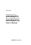
Product Configuration
- FX-DS110-COM…1
- AC Adapter with 1.8m cable…1
- Tapping screws (for mounting on wall, etc.)…2
- Locking screw (for connecting to ground wire)…1
- Magnets (for mounting on metallic surfaces)…2
- Rubber feet…4
- RS-232C Cross cable…1
- Floppy disk…1
- Manual…1
- Installation Guide…1
RX
LIN K
WRX
WLINK
POWER
RS-232C Cross cable x 1
AC Adapter x 1
FX-DS110-COM
Tapping screw x 2
User's Manual
Installation
Guide
User's Manual
Floppy disk x 1
Rubber feet x 4
Magnet x 2
Locking screw x 1
Check the contents to make sure that you have everything listed
above. If you do not have all the items, contact your distributor
or CONTEC group office where you purchased.
ii
FX-DS110-COM
Table of Contents
Copyright ............................................................................i
Trademarks ........................................................................i
Product Configuration ..................................................... ii
1. Introduction ............................................................. 1
Features.........................................................................1
Terminology/Abbreviations...........................................1
Limited One-Year Warranty.........................................2
How to Obtain Service..................................................2
Liability .........................................................................2
Handling Precautions...................................................3
Precautions for Use.......................................................3
Precautions Related to Service ....................................4
About the Manual .........................................................5
2. Overview .................................................................. 7
Component Locations........................................................7
LED Indicators ..................................................................8
Mode Switches...................................................................9
ID Switches ..................................................................... 11
3. Explanation in Mode of Operation ............................ 13
Wireless Mode .................................................................13
ADHOC (Simple Mode)...............................................13
Infrastructure (Standard Mode / Compatible Mode) 14
Through Mode .................................................................15
Modem Mode ...................................................................17
Virtual COM Mode..........................................................19
Terminal Mode ................................................................20
Wireless of operating Modes and Communications ......20
4. Setup ..................................................................... 21
Wall Installation .............................................................21
Using the Mounting Screws (Included) .....................21
Using the Magnets (Included)....................................22
FX-DS110-COM
iii
Table Top Installation .....................................................24
Cable Installation ...........................................................24
Connection of a Power Supply........................................25
Ground Connection .........................................................25
FX-ANT-P2(option) Connection .....................................26
5. Settings ................................................................. 27
Setup Procedures ............................................................27
Through Mode .............................................................27
Modem Mode ...............................................................29
Virtual COM Mode......................................................31
Utility Software Settings................................................33
Preparation of Utility Software .................................33
Starting of Utility Software .......................................33
Connection Environment............................................35
Node Registration .......................................................37
Configuration ..............................................................38
File Management ........................................................48
Status ..........................................................................49
Communication Test...................................................56
Modem command ............................................................59
Example of a data set (wording of a telegram) .........61
(1) @RAR......................................................................62
(2) @CAB......................................................................62
(3) @RBS ......................................................................63
(4) @RRS ......................................................................64
(5) @INI .......................................................................64
(6) @RSD......................................................................65
(7) @RSE......................................................................65
(8) @CRB......................................................................65
(9) @RRG .....................................................................66
(10) @RST ....................................................................66
(11) @CTB ....................................................................66
(12) @VER....................................................................67
(13) @TXT ....................................................................67
(14) @TXB....................................................................68
(15) @TXE....................................................................68
iv
FX-DS110-COM
(16) @TXU ...................................................................69
(17) @RXT....................................................................70
(18) @RXB....................................................................70
(19) @RXE....................................................................71
(20) @RXU ...................................................................72
(21) @RXN ...................................................................73
(22) @PIG.....................................................................74
(23) @ECO ...................................................................74
(24) @SAV ....................................................................74
(25) @RES ....................................................................75
(26) @RRT....................................................................75
Setup of a virtual COM driver........................................76
Correspondence OS.....................................................76
Cautions on Use ..........................................................76
Install ..........................................................................77
6. SNMP Agent Functions ........................................... 79
SNMPc Overview ............................................................79
MIB Support....................................................................80
Control Using SNMPc.....................................................81
Building-in to SNMPc .....................................................82
MIB Database Updates...................................................82
7. Troubleshooting ...................................................... 83
When Communication Fails .......................................83
When SNMP Connections Fail...................................84
When the COM Will Not Start ...................................85
8. Appendix ................................................................ 87
Product Specifications.....................................................87
Input/Output Interface ...................................................89
RS-232C Port Pin Assignments..................................89
Memory register ..............................................................90
Glossary ...........................................................................94
9. Index ..................................................................... 99
FX-DS110-COM
v
List of Figures
Figure 2.1.
Component Locations............................................... 7
Figure 2.2.
ID Switches .............................................................11
Figure 3.1.
ADHOC ................................................................. 13
Figure 3.2.
Infrastructure.......................................................... 14
Figure 3.3.
Through Mode........................................................ 16
Figure 3.4.
Modem Mode ......................................................... 18
Figure 3.5.
Virtual COM Mode ................................................ 19
Figure 4.1.
Wall Installation ..................................................... 21
Figure 4.2.
Attaching Magnets Figure ...................................... 22
Figure 4.3.
Removing Magnets................................................. 22
Figure 4.4.
Installation on a Steel Desk .................................... 23
Figure 4.5.
Cable Connection ................................................... 24
Figure 4.6.
Connection of a Power Supply................................ 25
Figure 4.7.
Ground Connection ................................................ 25
Figure 4.8.
FX-ANT-P2 Connection......................................... 26
Figure 5.1.
Main Menu............................................................. 33
Figure 5.2.
Connection Environment ........................................ 35
Figure 5.3.
Node Registration................................................... 37
Figure 5.4.
Base Configuration................................................. 39
Figure 5.5.
Wireless Configuration........................................... 42
Figure 5.6.
Detail Configuration............................................... 44
Figure 5.7.
SNMP Configuration.............................................. 47
Figure 5.8.
File Management.................................................... 48
Figure 5.9.
Status (Environment).............................................. 50
vi
FX-DS110-COM
Figure 5.10. Status (Interfaces)................................................... 51
Figure 5.11. Status (Management Information) .......................... 52
Figure 5.12. Status (Wireless Node) ........................................... 54
Figure 5.13. Status (Wireless Counter) ....................................... 55
Figure 5.14. Echo Back Test (Example Configuration)............... 56
Figure 5.15. Echo Back Test....................................................... 57
Figure 5.16. Buffer Status Representation .................................. 63
Figure 6.1.
Settings................................................................... 81
Figure 8.1.
External Dimensions .............................................. 87
Figure 8.2.
Wiring Diagram for Supplied RS-232C Cable ........ 88
Figure 8.3.
Multi-channel Operation......................................... 97
Figure 8.4.
Channel Frequencies .............................................. 98
FX-DS110-COM
vii
List of Tables
Table 2.1.
ADHOC (Simple Mode) ............................................. 8
Table 2.2. Infrastructure (Standard Mode) ................................... 8
Table 2.3.
Other........................................................................... 8
Table 2.4.
Other........................................................................... 9
Table 2.5.
Mode Switches.......................................................... 10
Table 3.1.
Wireless of operating Modes and Communications... 20
Table 5.1.
Base Configuration
< 1 / 2 > .................................. 40
Table 5.1.
Base Configuration
< 2 / 2 > .................................. 41
Table 5.2.
Wireless Configuration ............................................. 43
Table 5.3. Settings for each operating mode .............................. 45
Table 5.4. SNMP Configuration ................................................ 47
Table 5.5. Status ........................................................................ 49
Table 5.6.
Command List .......................................................... 59
Table 6.1.
Group Names ............................................................ 80
Table 8.1. Physical Specifications.............................................. 87
Table 8.2. Software Specifications............................................. 87
Table 8.3. Installation Environment Conditions (Environment
Specifications)........................................................ 87
Table 8.4.
RS-232C Port Pin Assignments................................. 89
Table 8.5.
Memory Register List
< 1 / 3 > .............................. 90
Table 8.5.
Memory Register List
< 2 / 3 > .............................. 91
Table 8.5.
Memory Register List
< 3 / 3 > .............................. 92
Table 8.6.
Device ID vs. IP Address Table (For Communication
via a Router Only) .................................................. 93
viii
FX-DS110-COM
Introduction
1. Introduction
Thank you for purchasing the FX-DS110-COM accesses point.
The FX-DS110-COM is a wireless COM adapter that uses DS
spread-spectrum transmission in the 2.4GHz band to connect RS232C interface devices via a wireless link. As the unit complies
with the IEEE 802.11b wireless LAN standard, it can also be
connected to a wired LAN via an access point.
This document explains how to use the FX-DS110-COM. Be sure
to read it carefully so that you can use the product correctly.
Features
- Connects RS-232C devices via a Wireless.
- Supports both 1:1 and 1:N communications
- Can be connected to a standard LAN via a wireless LAN access
point
- Easy setup using the ID switch and MODE switch
- RS-232C supports up to 921.6kbps *
- The wireless communications comply with IEEE802.11b.
- Supports Multi channel (US: 1 ~ 11, EU: 1 ~ 13)
- A software setup utility is included
* Restrictions apply depending on the cable length and the device
with which you are communicating.
Terminology/Abbreviations
The following terms and abbreviations are used in this manual for
convenience.
Full term
Term used in this manual
FX-DS110-APE, FX-DS110-APL
Access point/AP
A device with the wireless function
User unit/
Wireless terminal
Personal computer
PC
FX-DS110-COM
1
Introduction
Limited One-Year Warranty
CONTEC Interface boards are warranted by CONTEC Co., LTD. to
be free from defects in material and workmanship for up to one year
from the date of purchase by the original purchaser.
Repair will be free of charge only when this device is returned
freight prepaid with a copy of the original invoice and a Return
Merchandise Authorization to the distributor or the CONTEC group
office, from which it was purchased.
This warranty is not applicable for scratches or normal wear, but
only for the electronic circuitry and original boards. The warranty
is not applicable if the device has been tampered with or damaged
through abuse, mistreatment, neglect, or unreasonable use, or if the
original invoice is not included, in which case repairs will be
considered beyond the warranty policy.
How to Obtain Service
For replacement or repair, return the device freight prepaid, with a
copy of the original invoice. Please obtain a Return Merchandise
Authorization Number (RMA) from the CONTEC group office
where you purchased before returning any product.
* No product will be accepted by CONTEC group without the
RMA number.
Liability
The obligation of the warrantor is solely to repair or replace the product.
In no event will the warrantor be liable for any incidental or
consequential damages due to such defect or consequences that arise
from inexperienced usage, misuse, or malfunction of this device.
2
FX-DS110-COM
Introduction
Handling Precautions
Take the following precautions when handling this board.
- Do not attempt to modify this device. The manufacturer will
bear no responsibility whatsoever for the device if it has been
modified.
- Do not store this device in high temperature or low temperature
surroundings, or expose it to rapid temperature changes.
(Operating temperature range: 0° to 50°C)
- Do not use or store this device where it is exposed to direct
sunlight or near stoves or other sources of heat.
- Do not use or store this device where it is exposed to dust or high
humidity.(Operating humidity range: 10-90%RH, without
condensation)
- This product contains precision electronic elements and must not
be used in locations subject to physical shock or strong vibration.
- Do not use or store this device near strong magnetic fields or
devices emitting electromagnetic radiation.
- If abnormal smells or heat are noticed, disconnect the power
supply immediately.
- In case of abnormal operation or failure, contact the store where
this product was purchased.
Precautions for Use
This product is classified as "wireless equipment for stations of
low-power data transmissions systems" under the Wireless
Telegraphy Act, and does not require a radio transmission license.
The law prohibits modification of the interior of this product.
FX-DS110-COM
3
Introduction
Precautions Related to Service
Clean the FX-DS110-COM by wiping lightly with a soft cloth
moistened with water or a cleaning solution.
Take care to avoid the use of benzene, thinners or other volatile
solutions which may cause deformation or discoloration.
Notes!
- The unauthorized reproduction of this document, in whole or in
part, is prohibited.
- The specifications, designs, and other contents of this document
are subject to change without notice.
- The contents of this document are believed to be accurate,
however if any discrepancies noted should be brought to the
attention of the store where this product was purchased.
- Notwithstanding the foregoing, the manufacturer is unable to
accept any claims for losses or lost profits, etc. Resulting from
the use of this product.
- MS, Microsoft, Windows, Windows NT, and MS-DOS are
registered trademarks or trademarks of Microsoft Corporation in
the U.S.A. and other countries.
Netscape Navigator is a registered trademark of Netscape
Communications.
Other names of companies and products used in this document
trademarks or registered trademarks of the related companies.
This document does not use the symbols ™ , ® , © etc.
Precautions Related to Electromagnetic Interference
This device complies with Part 15 of the FCC Rules. Operation is
subject to the following two conditions : (1) this device may not cause
harmful interference, and (2) this device must accept any interference
received, including interference that may cause undesired operation.
This equipment complies with part 15 of the FCC rules. Any changes or
modifications not expressly approved by the manufacturer could void
the user’s authority to operate the equipment.
CAUTION: To comply with FCC RF exposure compliance
requirements, a separation distance of at least 5 cm must be
maintained between this device and all persons.
4
FX-DS110-COM
Introduction
About the Manual
This manual consists of the following chapters:
Chapter 1
Introduction
Chapter 2
Overview
Chapter 3
Explanation in Mode of Operation
Chapter 4
Setup
Chapter 5
Settings
Chapter 6
SNMP Agent Functions
Chapter 7
Troubleshooting
Chapter 8
Appendix
Chapter 9
Index
FX-DS110-COM
5
Introduction
6
FX-DS110-COM
Overview
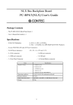
2. Overview
Component Locations
Front
Side
RSSI
WDATA
WLINK
CDATA
LED
POWER
Ground terminal
2
7
Ventilation Slits
9
B C DE
A
3 4 56
Power supply plug
F01
RS-232C connector
ID Switches
MODE Switches
Figure 2.1. Component Locations
Note!
Do not block the ventilation vents as this may result in damage or
malfunction due to overheating.
LED
The five LED indicators indicate the sending /receiving status of the
wireless or wired LAN, power supply, LAN connection status, etc.
MODE Switches
These are used to initialize the FX-DS110-COM, select the wireless
channel and baud rate, and set the operation mode.
ID Switches
Set the Device Number of FX-DS110-COM
FX-DS110-COM
7
Overview
LED Indicators
Table 2.1.
Name
POWER
ADHOC (Simple Mode)
Status
Indicator
Flashing
Startup, or startup error
On
Operating
Flashing
Receiving COM data
WLINK
On
Through Mode(Opposing device ID specified)
The specified device exists.
Through Mode(broadcast) or Modem mode
Another FX-DS110-COM is present on the network.
Virtual COM Mode
The RS-232C port is open.
WDATA
Flashing
Receiving wireless LAN data
RSSI
On
A wireless device is present with an RSSI value higher
than the RSSI threshold.
CDATA
Table 2.2.
Name
POWER
Infrastructure (Standard Mode)
Status
Indicator
Flashing
Startup, or startup error
On
Operating
CDATA
Flashing
Receiving COM data
WLINK
On
Wire LAN connection normal
WDATA
Flashing
Receiving wireless LAN data
RSSI
On
The RSSI value for the access point to which the unit is
logged in is higher than the RSSI threshold.
Table 2.3.
Name
POWER
POWER
CDATA
WLINX
Other
Status
Indicator
Flashing 2
times
Initialization error
Flashing 3
times
Firmware writing error
All flashing
at the same
time
Firmware writing in progress
WDATA
RSSI
8
FX-DS110-COM
Overview
Table 2.4.
Name
POWER
POWER
CDATA
WLINX
Other
Status
Indicator
Flashing 2
times
Initialization error
Flashing 3
times
Firmware writing error
All flashing
at the same
time
Firmware writing in progress
WDATA
RSSI
Mode Switches
These are used to initialize the FX-DS110-COM, select the wireless
channel and baud rate, and set the operation mode. The factory
default setting is to use the MODE switch settings. The default
MODE switch settings are all OFF.
When the device is in its factory default setting state, simple setup
can be performed using the MODE switches only. However, you
need to use the utility software or a terminal to set the security and
other detailed settings.
FX-DS110-COM
9
Overview
Table 2.5.
1
Mode Switches
Item
Description
INIT
Restore the RP-COM(FIT) to its factory default settings. When this switch is ON, the POWER
and COM LED’s start to blink.
Turning the switch OFF while the LEDs are still blinking (approx. 3 seconds) restores all
settings to their factory default values when the module is next restarted.
* Wait until the POWER and COM LEDs have gone back to their normal states before rebooting
or turning off the power.
2,3
Channel
1, 2
Selects the wireless channel. You can use the channel setting to divide units into network
groups. You can configure four independent network groups using the switch settings.
SW 2
SW 3
Channel
OFF
OFF
OFF
ON
CH1
CH1
ON
OFF
CH6
ON
ON
CH11
The above setting selects CH1, 6 and 11. The channel can also be set in the range 1 to 13 by
software (only EU). When setting by software, it is recommended that adjacent groups are
separated by at least five channels to prevent interference.
4,5
Baud Rate
1, 2
Set the Baud Rate of RS-232C ports.
Baud rate
SW 4
SW 5
OFF
OFF
OFF
ON
9,600bps
19,200bps
ON
OFF
38,400bps
ON
ON
115,200bps
The above setting selects 9,600, 19,200, 38,400 and 115,200bps. The channel can also be set in
the range 300, 600, 1,200, 4,800, 9,600, 14,400, 19,200, 38,400, 57,600, 115,200, 230,400,
460,800 and 921,600 by software.
6
ADHOC/
Wireless of operating Modes
operating mode
INFRA
7
Through/
OFF
ADHOC
Select this when using ADHOC (Simple Mode). All wireless
devices operate as peers and communication is performed
independently between communicating devices.
ON
INFRA
Select this when using Infrastructure (Standard Mode).
Communication is performed via access points.
Set the operating mode
operating mode
MODEM
OFF
Through
ON
MODEM
Select this when using Through Mode.
Select this when using Modem Mode.
* Virtual COM Mode is set by software.
8
TERM
Changes to Terminal Mode. Use the utility software for the COM connection. Set this ON
when performing maintenance on the FX-DS110-COM or using modem commands with “echo
back ON”.
All switches are set to OFF at factory.
10
FX-DS110-COM
Overview
ID Switches
23
7 9
B C DE
A
4 56
This sets the device ID for the FX-DS110-COM.
The setting range is 0 to F (0 to 15), but the ID can be set in the
range 0 to 254 by software.
The factory default setting is that the ID switch setting is used and
the device ID is set to “0”.
Factory setting:
(ID = 0)
F 01
Figure 2.2. ID Switches
FX-DS110-COM
11
Overview
12
FX-DS110-COM
Explanation in Mode of Operation
3. Explanation in Mode of Operation
Wireless Mode
ADHOC (Simple Mode) and Infrastructure (Standard
Mode/Compatible Mode) can be selected for wireless operation.
The operation of wireless communications is different for each
mode. In ADHOC (Simple Mode), all wireless devices operate as
peers. In Infrastructure (Standard Mode/Compatible Mode)
communication is performed via access points.
ADHOC (Simple Mode)
In ADHOC (simple mode), all wireless devices are paired, and can
use wireless communication with the other device in the pair.
Figure 3.1. ADHOC
Note!
When configuring a system using ADHOC (Simple Mode), restrict
the system to within a range where all devices can communicate
with each other. If devices are separated by too great a distance
or if walls or other obstacles block communications, this will cause
the “hidden device” problem and reduce throughput.
FX-DS110-COM
13
Explanation in Mode of Operation
Infrastructure (Standard Mode / Compatible Mode)
This mode allows the use of multiple AP's to configure wide-area
wireless LAN's. All communication between wireless terminals
must go through an AP.
Figure 3.2. Infrastructure
14
FX-DS110-COM
Explanation in Mode of Operation
Through Mode
This mode transfers data directly from the RS-232C device
connected to the FX-DS110-COM to the FX-DS110-COM with the
same device ID or with the specified device ID. This means
communications can be performed in the same way as if the 1-to-1
connection via an RS-232C cable has been replaced with a wired
network.
Existing applications that operate using RS-232C can continue to be
used without any changes.
However, the RS-232C parameters of the FX-DS110-COM and the
connected device must be the same.
You can use the utility software to specify the device ID of the other
FX-DS110-COM (opposing device ID).
If the opposing device ID is set in the range 0 to 254,
communication is performed with the device with the specified ID.
If 255 is specified, transmissions are sent to all FX-DS110-COM
devices in the network.
The wireless connection can be used in both ADHOC modes
whereby FX-DS110-COM devices communicate directly or in
Infrastructure mode where communication is via access points.
Notes!
- If using broadcasting, ensure that all FX-DS110-COM units have
different device IDs.
- Device ID 255 is reserved for broadcast use.
- If connecting to an Ethernet network via an access point, set
appropriate values for the IP address, subnet mask, and similar
parameters to prevent any problems on other LAN devices.
- Although, existing application can generally continue to be used
unchanged, note that they may not operate correctly if particular
RS-232C control procedures are used (see below).
(Example) - Baud rate changed during operation
- Hardware signals used for proprietary purposes
other than flow control
- RI signal used
FX-DS110-COM
15
Explanation in Mode of Operation
Figure 3.3. Through Mode
16
FX-DS110-COM
Explanation in Mode of Operation
Modem Mode
This mode performs RS-232C communications on a packet-bypacket basis using special commands to control the
FX-DS110-COM. As the device ID is added to the transmitted
packet data, communication can be performed with multiple
FX-DS110-COM devices.
As operation is controlled by commands, the device connected to
the RS-232C port of the FX-DS110-COM requires special
application software. Also, the type of data being sent or received
can be identified as either text data, binary data, Ethernet data, or
UDP/IP data. In particular, UDP/IP data can be used to
communicate directly with a Socket interface on a host PC.
The wireless connection can be used in both ADHOC mode
whereby FX-DS110-COM devices communicate directly or in
Infrastructure mode where communication is via access points.
The following three types of communication are supported.
(1) Communication with a specified device ID
Communication can be performed between RS-232C devices
connected to FX-DS110-COM units.
(2) Communications with UDP/IP Socket
Communications can be performed via access points with
Windows PC and workstation.
(3) Build and transmit or receive Ethernet frames
Communications can be performed via access points with
devices connected to the Ethernet using protocols other than
UDP/IP.
Notes!
- Ensure that the specified device IDs are unique
- Device ID 255 is reserved for broadcasting.
- To avoid any adverse effects on other LAN devices, set the IP
address, subnet mask, and other network parameters to
appropriate values.
FX-DS110-COM
17
Explanation in Mode of Operation
Figure 3.4. Modem Mode
18
FX-DS110-COM
Explanation in Mode of Operation
Virtual COM Mode
Virtual COM driver mode for Windows converts COM data to LAN
data to control the RS-232C port on an FX-DS110-COM via the
LAN. This has the effect of extending a 1-to-1 RS-232C cable
connection to operate via the LAN and allows existing applications
that use RS-232C to continue to be used changed.
Figure 3.5. Virtual COM Mode
Note!
To avoid any adverse effects on other LAN devices, set the IP
address, subnet mask, and other network parameters to appropriate
values.
FX-DS110-COM
19
Explanation in Mode of Operation
Terminal Mode
This mode is used to access the FX-DS110-COM via the RS-232C
port to perform maintenance using the utility software or modem
commands.
Setting the ID switch to “8” forcibly sets the FX-DS110-COM to
terminal mode.
When set to terminal mode, the RS-232C settings are as follows.
- Baud rate
: 9600bps
- Data bit
: 8bit
- Parity
: None
- Stop bit
: 1bit
- Flow control
: Hardware
Wireless of operating Modes and
Communications
Table 3.1.
FX-DS110-COM
FX-DS110-PCC
ADHOC
ADHOC
(Simple Mode)
(Simple Mode)
FX-DS110-APE
Simple Mode
Infrastructure
Infrastructure
Standard,
(Standard Mode)
(Standard, BRouter)
Brouter
Infrastructure
Infrastructure
(Compatible)
(Compatible Mode)
20
Wireless of operating Modes and Communications
Compatible
FX-DS110-COM
FX-DS110-APL
ADHOC
(Simple Mode)
Infrastructure
(Standard)
Infrastructure
(Compatible Mode)
Setup
4. Setup
Wall Installation
Using the Mounting Screws (Included)
Place the screws in the wall according to the mounting diagram,
then mount the unit.
It is also possible to remove the cover from the unit, then remove
the wireless card and screw the unit onto the wall directly.
Diagram 1
(2)
(1)
(3)
(1) Place the screws in the wall according to the mounting diagram
(2 screws).
(2) Position the AP unit so that the two wall mount holes in the AP unit
fit over the two screws in the wall.
(3) Slide the AP unit down to hold it in place.
Diagram 2
(1)
(2)
(3)
(1)
(1) Press here to open the lid.
(2) Slide the cover in the direction shown and release the
catch. Remove the wireless card.
(3) Insert the screw to attach the unit. After mounting,
replace the wireless card and cover.
Figure 4.1. Wall Installation
Note!
Do not obstruct the ventilation slits. This can cause the
temperature inside the product to rise and can damage the
components inside.
WLINK
WRX
LIN K
RX
FX-DS110-COM
PO WER
Caution!
Do not install this unit upside down. This will
cause heat to accumulate and possible cause fire.
21
Setup
Using the Magnets (Included)
The magnets included with this product can be used for easy
mounting and removal on steel desks, partitions, or other metal
surfaces.
Notes!
- Do not place magnets near monitors, floppy disks, or other
sensitive objects.
- Moving the AP while it is mounted on a steel desk or similar
surface can cause paint scratching.
Attaching and Removing Magnets
To mount the unit using a magnet, push the magnet into the magnet
mounting hole in the direction of arrow 1 as shown in Figure 4.2. ,
then insert the entire magnet into the mounting hole.
Next, slide the magnet in the direction of arrow 2 to hold the unit in
place.
To remove, slide the magnet in the direction of arrow 1 in Figure
4.3. , then lift in the direction of arrow 2.
Magnet
Magnet mounting holes
Figure 4.2. Attaching Magnets
22
Figure 4.3. Removing Magnets
FX-DS110-COM
Setup
Mounting on Steel Desks or Partitions
The unit can be mounted directly on steel desks or partitions.
lightly to make sure that the AP does not come off easily.
Pull
For better receiving sensitivity, mount the antenna against the steel
surface.
Antenna area
Figure 4.4. Installation on a Steel Desk
FX-DS110-COM
23
Setup
Table Top Installation
Use the rubber pads included with the unit.
To install on a table top, choose a sturdy, level surface with a wellventilated space (approx. 5 cm.) in all directions. Wireless
equipment has a larger sending and receiving range when it is in a
highly visible location. Choose a location where the sight lines are
as clear as possible.
Note!
Do not obstruct the ventilation slits. This can cause the
temperature inside the product to rise and can damage the
components inside.
Cable Installation
Connect the RS-232C connector to the RS-232C cross cable.
RX
LINK
WRX
WLINK
POWER
RX
LINK
WRX
WLIN K
PO WER
RS-232C cross cable
PC
Serial(RS-232C) port
Figure 4.5. Cable Connection
Note!
The FX-DS110-COM operates as a DTE (Data Terminal
Equipment) device.
Use a straight-through cable if connecting to a DCE (Data Circuitterminating Equipment) device.
24
FX-DS110-COM
Setup
Connection of a Power Supply
Connect the supplied AC adapter to the power input connector.
PC
Serial(RS-232C) port
RX
LINK
WRX
WLIN K
AC Adapter
PO WER
Figure 4.6. Connection of a Power Supply
Note!
Only use the AC adapter supplied with the unit. Unauthorized
adapters may cause damage or accidents due to overheating.
Ground Connection
Remove the rubber cover from the ground terminal, and connect the
ground wire using the locking screws (included).
Remove rubber cover
Figure 4.7. Ground Connection
Note!
In some installation environments, the ground terminal may become
hot
FX-DS110-COM
25
Setup
FX-ANT-P2(option) Connection
CONTEC recommends use of the optional antenna (FX-ANT-P2) if
the antenna of the device itself is hidden by an obstruction.
(1)
(2)
(3)
(1)
WIRELESS LAN CARD
(4)
WIRELESS LAN CAR D
RX
LINK
WRX
WLIN K
PO WER
R3cm or more
(1) Press here to open the top cover.
(2) Slide the top cover and release the clip.
Remove the wireless card.
(3) Unplug the antenna from the wireless card and insert
the two FX-ANT-P2 antennas into the wireless card.
(4) Reinsert the card than replace the top cover.
Figure 4.8. FX-ANT-P2 Connection
Note!
To prevent any adverse effect on the coaxial cable characteristics,
ensure the cable bend radius is never less than 3cm.
26
FX-DS110-COM
Settings
5. Settings
Setup Procedures
Through Mode
Simple setup procedure (Only MODE switch and ID switch)
(1) Set the operation mode to Through Mode (Set MODE switch 7
to OFF)
(2) Select to Wireless of operating Modes (ADHOC,
Infrastructure)
(3) Select to Baud rate of RS-232C (9,600bps, 19,200bps,
38,400bps, 115,200bps)
(4) Select the wireless channel (1, 6, or 11)
(5) Use the ID switch to set the device ID (Set the ID of the
opposing device.)
(6) Restart
Advanced setting procedure (Using the utility software)
(1) Use “Connection Environment” to specify how to connect to
the device on which to perform maintenance.
(2) Set MODE switch 8 to ON to select Terminal Mode.
(3) Create the device list by using “Node Registration” to perform
an automatic search or by adding new device entries.
(4) Use “Configuration” to clear the “Enable MODE Switch”
check box in the operating environment settings and set the
operation mode to “Through Mode”.
(5) Set the settings you wish to change.
(6) Set the desired items.
(7) Use the [Reboot] button to reboot the device.
(8) Set MODE switch 8 to OFF.
* Once you have performed steps (1) and (3), you do not need to
repeat them each time unless there have been some changes.
When modifying settings on a device that has already been setup,
you must first use the [Read] button to read the current settings.
FX-DS110-COM
27
Settings
Advanced setting procedure (Using modem commands from a
terminal)
(1) Set MODE switch 8 to ON to select Terminal Mode.
The RS-232C settings are preset to 9,600bps, 8 data bits, no
parity, 1 stop bit, and hardware flow control. Keyboard input
is echoed back.
(2) Use the @RRG command to set REG003 to “ignore MODE
switches” and REG005 to “Through Mode”.
(3) Use the @RRG command to modify the desired settings.
(4) When you have finished changing settings, use the @SAV
command to save the settings.
Use the @RES command if you wish to apply the new settings
temporarily without saving.
(5) Use the @RST command to reboot the unit.
(6) Set MODE switch 8 to OFF.
If wireless operation is set to ADHOC mode, the WLINK LED
illuminates after the unit is rebooted if an opposing
FX-DS110-COM device is detected. In Infrastructure mode,
the WLINK LED illuminates when the device logs into the
access point.
Note!
If connecting to an Ethernet network via an access point, set
appropriate values for the IP address, subnet mask, and similar
parameters to prevent any problems on other LAN devices.
28
FX-DS110-COM
Settings
Modem Mode
Simple setup procedure (Only MODE switch and ID switch)
(1) Set the operation mode to Modem Mode (Set MODE switch 7
to ON)
(2) Select to Wireless of operating Modes (ADHOC,
Infrastructure)
(3) Select to Baud rate of RS-232C (9,600bps, 19,200bps,
38,400bps, 115,200bps)
(4) Select the wireless channel (1, 6, or 11)
(5) Use the ID switch to set the device ID (Set the ID of the
opposing device.)
(6) Restart
Advanced setting procedure (Using the utility software)
(1) Use “Connection Environment” to specify how to connect to
the device on which to perform maintenance.
(2) Set MODE switch 8 to ON to select Terminal Mode.
(3) Create the device list by using “Node Registration” to perform
an automatic search or by adding new device entries.
(4) Use “Configuration” to clear the “Enable MODE Switch”
check box in the operating environment settings and set the
operation mode to “Modem Mode”.
(5) Set the settings you wish to change.
(6) Set the desired items.
(7) Use the [Reboot] button to reboot the device.
(8) Set MODE switch 8 to OFF.
* Once you have performed steps (1) and (3), you do not need to
repeat them each time unless there have been some changes.
When modifying settings on a device that has already been setup,
you must first use the [Read] button to read the current settings.
FX-DS110-COM
29
Settings
Advanced setting procedure (Using modem commands from a
terminal)
(1) Set MODE switch 8 to ON to select Terminal Mode.
The RS-232C settings are preset to 9,600bps, 8 data bits, no
parity, 1 stop bit, and hardware flow control. Keyboard input
is echoed back.
(2) Use the @RRG command to set REG003 to “ignore MODE
switches” and REG005 to “Modem Mode”.
(3) Use the @RRG command to modify the desired settings.
(4) When you have finished changing settings, use the @SAV
command to save the settings.
Use the @RES command if you wish to apply the new settings
temporarily without saving.
(5) Use the @RST command to reboot the unit.
(6) Set MODE switch 8 to OFF.
If wireless operation is set to ADHOC mode, the WLINK LED
illuminates after the unit is rebooted if another
FX-DS110-COM device on the network is detected. In
Infrastructure mode, the WLINK LED illuminates when the
device logs into the access point.
Note!
If connecting to an Ethernet network via an access point, set
appropriate values for the IP address, subnet mask, and similar
parameters to prevent any problems on other LAN devices.
30
FX-DS110-COM
Settings
Virtual COM Mode
Advanced setting procedure (Using the utility software)
(1) Use “Connection Environment” to specify how to connect to
the device on which to perform maintenance.
(2) Set MODE switch 8 to ON to select Terminal Mode.
(3) Create the device list by using “Node Registration” to perform
an automatic search or by adding new device entries.
(4) Use “Configuration” to clear the “Enable MODE Switch”
check box in the operating environment settings and set the
operation mode to “Virtual COM Mode”.
(5) Set the settings you wish to change.
(6) Set the desired items.
(7) Use the [Reboot] button to reboot the device.
(8) Set MODE switch 8 to OFF.
* Once you have performed steps (1) and (3), you do not need to
repeat them each time unless there have been some changes.
When modifying settings on a device that has already been setup,
you must first use the [Read] button to read the current settings.
Advanced setting procedure (Using modem commands from a
terminal)
(1) Set MODE switch 8 to ON to select Terminal Mode.
The RS-232C settings are preset to 9,600bps, 8 data bits, no
parity, 1 stop bit, and hardware flow control. Keyboard input
is echoed back.
(2) Use the @RRG command to set REG003 to “ignore MODE
switches” and REG005 to “Virtual COM Mode”.
(3) Use the @RRG command to modify the desired settings.
(4) When you have finished changing settings, use the @SAV
command to save the settings.
Use the @RES command if you wish to apply the new settings
temporarily without saving.
(5) Use the @RST command to reboot the unit.
FX-DS110-COM
31
Settings
(6) Set MODE switch 8 to OFF.
If wireless operation is set to ADHOC mode, the WLINK LED
illuminates after the unit is rebooted if another FX-DS110COM device on the network is detected. In Infrastructure
mode, the WLINK LED illuminates when the device logs into
the access point.
Note!
If connecting to an Ethernet network via an access point, set
appropriate values for the IP address, subnet mask, and similar
parameters to prevent any problems on other LAN devices.
32
FX-DS110-COM
Settings
Utility Software Settings
This is a Windows application for detecting devices on the network,
reading and writing setup data, upgrading firmware, and displaying
status information.
These maintenance operations can be performed from a Windows
PC via either the LAN or COM port.
Preparation of Utility Software
(1) Insert the floppy disk (provided) in the A: drive of the
computer.
(2) Open the Explorer.
(3) Use Explorer to copy the file 'XCOMUTIL.EXE' from the
floppy disk to the appropriate directory.
Example:
C:\WLANUTIL\
Starting of Utility Software
Double click on the XCOMUTIL.EXE file to open the Access Point
Maintenance Utility.
You will see the following main menu.
Figure 5.1. Main Menu
FX-DS110-COM
33
Settings
Connection environment
This sets up the utility software. These settings need to be set
before you can perform maintenance operations.
Node registration
Edits the access point name list.
This list is used to detect devices connected by wired or wireless
connection. Device names are added or deleted using the edit
function.
Configuration
Maintains configuration information.
View or enter settings for the selected devices.
File management
Used for firmware maintenance.
View firmware version, or write firmware.
Status
Displays access point information.
View and verify information about the selected device.
Communication test
Performs a simple communications test.
Exit
Program exit.
34
FX-DS110-COM
Settings
Connection Environment
This specifies the setup data used by the utility software to perform
device maintenance.
These settings are required to setup communications between the
utility software and the network devices. You must set these
settings before performing operations such as registering devices
using an automatic search, setting up devices, upgrading firmware,
or displaying status information.
Figure 5.2. Connection Environment
Parameter
Description
LAN
Perform device maintenance via the LAN port.
COM
Perform device maintenance via the COM port.
Port
Select the COM port name on the Windows PC.
Baudrate
Set the communication speed.
Mode
Select the operating mode of the connected device.
Settings table for using the COM port
Utility software
RP-COM(FIT)
Mode
Baudrate
Terminal Mode
Modem Mode
Modem Mode
O
O
Set same value as set on device
Through Mode
O
×
Virtual COM Mode
O
×
Set values that permit
communications on both sides
O: allowed, ×: not allowed
FX-DS110-COM
35
Settings
Notes!
- To use terminal mode, the ID switch on the device must be set to
“F”.
- When using modem mode, if the RS-232C settings (data bits,
parity, and stop bits) on the device are different to those listed
below, use terminal mode to modify the settings.
Parameter
36
Setting value
Data bit
8 bit
Parity
None
Stop bit
1 bit
Flow control
Hardware
FX-DS110-COM
Settings
Node Registration
This registers data for the devices on the network. Maintenance
operations such as changing settings or upgrading the firmware are
performed based on the data registered here. You must always
perform node registration.
Assigning names to the devices found by the automatic search
makes it easier to identify the devices on the network.
Enter a name of up to 32 characters. A maximum of 255 devices
can be registered.
Figure 5.3. Node Registration
Button
Description
Search
This automatically detects and registers all devices connected to the same
network group. If you also wish to manage devices located on the far side of an
IP router, use the “New” button to register each device directly.
Clear
Deletes all registered data.
New
Registers data for a new device to be managed.
Delete
Deletes the data for the device selected in the node list
Exit
Returns to the main menu.
To modify the data displayed in the node list, double click on the
node you wish to modify to open an edit window.
You can also use the “File” menu to save the current node list data
to the hard disk or load a previously saved file.
FX-DS110-COM
37
Settings
Configuration
This reads and writes the settings for the device selected in the
“Node Name” field.
You can set basic parameters such as the operating mode as well as
SNMP and other detailed parameters.
To apply your changes, write the settings to the device and then
reboot it.
You can also use the “File” menu to save the currently displayed
settings to the hard disk or load a previously saved file.
Button
Description
Password
Change the password for the selected device.
To change, enter the current password and new password.
The new password does not become active until the device is rebooted.
The password can be up to 6 alphanumeric characters and is case sensitive.
Read
Read the settings for the selected device.
Write
Write the currently displayed settings to the selected device.
The new settings do not become active until the device is rebooted.
Default
Restore the factory default settings.
To apply these settings, write the settings to the device and then reboot it.
Reboot
Reboot the selected device.
Exit
Returns to the main menu.
* Password input is required for the “Password”, “Read”, “Write”, and “Reboot” commands.
The factory default setting is no password. In this case, you do not need to enter anything.
38
FX-DS110-COM
Settings
Base Configuration
This sets the IP parameters and other basic operating settings for the
device. You must always set the IP parameters if installing the
device in an existing network.
Figure 5.4. Base Configuration
FX-DS110-COM
39
Settings
Table 5.1.
Parameter
Memory
register
Base Configuration
Factory
setting
<1/2>
Input range
Description
Enable MODE
Switch
REG003
Enabled
Enabled/Disabled
Specifies whether to use the MODE switch
setting.
If disabled, the operation mode, network
mode, baud rate, and wireless channel can be
set from the utility software.
* Always disable this setting if using the
utility software to set Virtual COM Mode.
Mode
REG005
Switch
Through Mode /
Modem Mode /
Virtual COM Mode
Set the operating mode you wish to use.
Switch
ADHOC
(Simple Mode)/
Infrastructure
(Standard Mode)/
Infrastructure
(Compatible Mode)
Set the wireless operation mode.
Switch
300/
600/
1,200/
2,400/
4,800/
9,600/
14,400/
19,200/
38,400/
57,600/
115,200/
230,400/
460,800/
921,600
Set the communication speed of the RS-232C
port.
*These must match the settings for the device
connected to the RS-232C port.
US: 1~11
EU: 1~13
Set the wireless channel number. The setting
method differs depending on the operating
mode.
ADHOC : Only one can be set.
Infrastructure
Extended Roaming Disabled : Auto
Extended Roaming Enabled : More than one
can be set.
Network Mode
Baudrate
Channel
40
REG045
REG006
REG012
Switch
FX-DS110-COM
Settings
Table 5.1.
Parameter
Enable ID
Switch
Memory
register
REG001
Base Configuration
Factory
setting
Enabled
<2/2>
Input range
Enabled/Disabled
Description
Specifies whether to use the ID switch
setting.
Set the ID number to identify the device.
ID
REG002
Switch
0~254
Mode
Setting value
Through
Set the same ID to
each device pair
Modem
Different ID for each
device
Virtual COM
Not used
IP Address
REG071
~REG074
10.x.x.x
*1
Set the IP address mask assigned by the
network administrator. *2
Subnet Mask
REG075
~REG078
255.0.0.0
Set the subnet mask assigned by the network
administrator. *2
Default
Gateway
REG079
~REG082
0.0.0.0
Set the IP address of the default gateway. *2
ESSID
Transmit Rate
REG013
~REG044
REG046
"LocalGroup"
32 standard
alphanumeric
characters (case
sensitive)
Set the name of the wireless LAN network.
Communication cannot be performed between
wireless devices with different names.
Accordingly, changing this name divides from
the network.
Auto
(All)
1Mb/s /
2Mb/s /
Auto(1Mb/s, 2Mb/s) /
5.5Mb/s /
11Mb/s /
Auto(All)
Sets the communication speed for wireless
transmission.
*1: Factory setting of IP Address
A unique value is assigned using the lower 3 bytes of the 6-byte Ethernet address.
ex.)Ethernet address
IP address
00-80-4C-01-02-03
→
10.1.2.3
00-80-4C-0D-0E-0F
→
10.13.14.15
The initial '10' is common to all settings.
*2: When installing the device in an existing network or when connecting to an Ethernet network via an access point,
set appropriate values for these parameters to prevent any problems on other LAN devices.
FX-DS110-COM
41
Settings
Wireless Configuration
Sets the wireless parameters for the device.
Figure 5.5. Wireless Configuration
42
FX-DS110-COM
Settings
Table 5.2. Wireless Configuration
Parameter
Memory
register
Factory
setting
Input range
Disabled/
Type1/
Type2
Description
Set a proprietary encryption procedure for
wireless data. Typically, “Type 2” is specified
when encryption is enabled. However, select
“Type 1” if communicating with devices that
do not support type 2.
REG048
REG047
Disabled
Scramble Key
REG049
~REG058
Set 0
to all
Hexadecimal value
(0 to 9, A to F)
Set the key to use for wireless data
encryption.
Enable(WEP)
REG059
Disabled
Enable/Disabled
Specify whether to use the WEP function.
Default Tx
Key
REG060
1
1~4
Specify the WEP key number to use for data
transmission.
Key1
REG144
~REG157
Set 0
to all at
40bit
Hexadecimal value
(0 to 9, A to F)
Key2~4
REG161
~REG208
Disabled
Hexadecimal value
(0 to 9, A to F)
Extended
Roaming
REG108
Disabled
Enable/Disabled
Sets the AP roaming method. *1
If enabled, preferred APs to log into can be
specified.
Roaming
Threshold
REG111
Impossible
(80)
50~150
Set the threshold value for initiating
roaming. *2
Roaming is performed if the average RSSI
value during the RSSI sampling time is less
than this value.
RSSI
Sampling
Time
REG112
Impossible
(3seconds)
1~10
Set the sampling time (seconds) for obtaining
the RSSI value to use for initiating roaming.
*2
AP Login
Priority
REG113~
REG142
Cannot be
set (no
registration)
Login Other
AP
REG143
Impossible
(log in)
Scramble
* You cannot communicate with devices that
have a different encryption setting. Also note
that, when “Type 1” is set, bridge data is
padded to an even number.
Specify the WEP key for WEP encryption. To
perform communications using the WEP
function, the key placed in the default send
key number used for transmission must be
the same as the key placed in the same
location on the receiver.
Set the preferred APs to log into. *2
Up to 5 APs can be specified. APs in lower
numbered positions have higher priority.
Enable(log in)/
Disabled(do not log in)
Specify whether logging in to other than the
specified APs is permitted. *2
*1: Only applicable when set as a station in infrastructure mode.
*2: Can only be set when enhanced roaming is enabled.
FX-DS110-COM
43
Settings
Detail Configuration
Set the various parameters required for communicating in each
operation mode. As the parameters differ between operation
modes, refer to the table below.
Figure 5.6. Detail Configuration
44
FX-DS110-COM
Settings
Table 5.3.
Parameter
Memory
register
Settings for each operating mode
Factory
setting
Input
range
Mode
(1) (2) (3)
Description
Remote ID
REG084
None
0 to 255/
None
O
×
×
Set the ID of the opposing device with which
you are communicating. Set “255” if sending
to all devices in the same network group.
Data Bit
REG008
8 bit
8 bit/7 bit
O
O
O
Set the number of data bits for the RS-232C
port communication data. *1
Parity
REG009
None
None/Odd/
Even
O
O
O
Set the parity of the RS-232C port
communication data. *1
Stop Bit
REG010
1 bit
1 bit/
2 bit
O
O
O
Set the number of stop bits for the RS-232C
port communication data. *1
Flow
control
REG007
Hardware
Hardware/
XON/XOFF/
None
O
O
O
Set the flow control method for the RS-232C
port. *1
Rx
Timeout
REG011
5msec
0 to 255
O
×
O
Set the inter-character timeout milliseconds)
for characters output to the device. If the gap
between characters is longer than the time set
here, the data is sent via the network port.
RSSI
Threshold
REG083
80
1 to 150
O
O
O
Set the reception level threshold for
illuminating the RSSI LED.
Address
Table
Rx Output
Control
IP Table
000 to 254
REG089
Timeout
REG086
Response
REG087
to REG088
Rx Type
REG090
0.0.0.0
Prohibition
Prohibition/
Permission
O
O
×
Set the IP addresses corresponding to the
device IDs. Set this table if using devices on
the other side of a router or if using a
predefined correspondence between device IDs
and IP address. *2
×
O
×
Specify whether to output received data to the
terminal from immediately after booting.
3sec
0 to 255
×
O
×
Set the timeout time (seconds) for modem
commands. If the end of a command string is
not received within this time, the command is
discarded. However, commands are not
discarded in terminal setup mode.
Response
altogether
Response/
No response
×
O
×
Specify for each message whether or not to
issue replies to modem commands. *3
×
Specify the type of packets for which to output
data received from the wired network to the
terminal. *4
If UDP is specified, you can specify four ranges
of port numbers that you wish to receive. If
you wish to receive data from a specific port
only rather than a range, just specify the same
port number in both fields.
Binary,
Text
Binary/
Text/
MAC/
UDP
×
O
FX-DS110-COM
45
Settings
*1 These must match the settings for the device connected to the RS-232C port.
Button
Description
*2
New
Register a new table entry
Delete
Delete the selected table entry
Use Node list
Set the data entered using “Node Registeration”.
To change the displayed data, double click on the entry you wish to modify.
This opens an edit window.
*3 As the end of the command message differs depending on the command, refer to the
“Modem Commands” section below.
*4 Response message
Response message
Description
“OK”
Command Error
“E1”
Invalid command or parameter
Resource Error
“E2”
Unable to execute command because of
insufficient internal resources.
Timeout Error
“E3”
No response from opposing device for a command
that expects a response
(e.g. @PIG).
Exec.Error
“E4”
An error other than those listed above occurred
during command processing.
*5 Receiving packet type
Rx Type
Successful completion
Receivable data
Character sequence
Binary
- Data sent by @TXB command
- Data sent by through mode device
“@RXB”
Text
- Data sent by @TXT command
“@RXT”
MAC
- Data sent by @TXE command
- Ethernet frame received from wired network.
“@RXE”
UDP
- Data sent by @TXU command
- UDP frame received from wired network.
(If a UDP port is specified, the data is from that port)
“@RXU”
Note:
46
Character
OK
If both MAC and UDP are enabled, data identified as UDP data is treated
accordingly and other data is treated as MAC data.
FX-DS110-COM
Settings
SNMP Configuration
Set these settings when using the SNMP agent function.
Figure 5.7. SNMP Configuration
Table 5.4.
Parameters
Factory
settings
SNMP Configuration
Input range
Description
Community
Name
“public”
31 standard
SNMP verification string. This acts like a password for
alphanumeric characters access using SNMP. The SNMP administrator can use
(case sensitive)
this name to access the device’s MIB information.
Access
Read & Write
Read & Write /
Read Only
Set access permissions for community name.
Set whether “Read Only” or “Read & Write” is
permitted.
Send Trap
Disabled
Enabled / Disabled
Specify whether to notify the SNMP administrator of
MIB data access errors and startup (coldStart).
IP Address
With no setup
Name
With no setup
A character string of up
to 31 characters
Set the SNMP device name for the network device.
With no setup
A character string of up
to 31 characters
Set the physical location of the network device. For
example, “Development Dept., 8th Floor”
With no setup
A character string of up
to 31 characters
Set the administrator contact details for the network
device.
For example, set the network administrator’s name and
telephone number.
Location
Contact
Set the IP address to which to send SNMP trap packets.
Can only be set when “Send Trap” above is enabled.
FX-DS110-COM
47
Settings
File Management
This dialog is used to get the current firmware version of devices on
the network, perform firmware upgrades, and read or write the
settings file.
Figure 5.8. File Management
Button
Description
Get Version
Retrieves the version number from all devices connected to the same network group or from a
specified device only. To get information from devices on the other side of a router, you need to
specify the device explicitly. In this case, the device’s IP address must have been set correctly.
Read
Read the firmware and settings file and save on the hard disk. *1
Write
Write the firmware and settings file from the hard disk to the selected device. *1
Reboot
Reboot the selected device.
* You cannot perform a [Reboot] on a device in terminal setup mode. In this case, change the device
ID switch back to its correct setting then turn the device power off then on again.
Exit
Returns to the main menu.
Select the file and directory name.
Browse
Type
Selected File
Firmware
File Name
Configuration File
Directory Name
*1: File name
The file name contains the lower 3 bytes of the MAC address of the selected device.
(ex.) 00-80-4C-4D-20-5E → 4D205E.TXT
48
FX-DS110-COM
Settings
Status
Reads operating information such as the environment settings and
the send and receive counters from the device specified by “Node
Name” and displays on the screen. The send and receive counters
can also be cleared. However, data can only be cleared when
scanning is stopped.
Table 5.5.
Status
Button
Description
Exit
Returns to the main menu.
Scan Start
Reads data periodically (at the number of seconds specified by “Interval”).
If “Interval” is “0”, data is read once only.
Stop
Stops reading data.
FX-DS110-COM
49
Settings
Environment
Displays the current operating environment for the specified device.
Figure 5.9. Status (Environment)
Parameters
50
Description
Loader Version
Version number of program for executing firmware.
Firmware Version
The version number of a firmware.
Firmware
Version(Wireless Card)
Version number of wireless card firmware
Hardware Version
The version number of a hardware.
Machine ID
The device number set up now.
Terminal Mode
Current terminal mode status
Mode
Current operating mode
Network Mode
Current operating mode of Wireless
Baudrate
Current RS-232C port communication speed
Channel Number
Current wireless channel number
Card Type
Wireless card type
Ethernet Address
Ethernet address allocated to device.
Wireless MAC Address
Wireless MAC address assigned to device
IP Address
Current IP address set for device
Subnet Mask
The subnet mask set up now.
Default Gateway
The IP address of the default gateway set up now.
FX-DS110-COM
Settings
Interfaces
Displays data for the device’s RS-232C and Ethernet interfaces
including send and receive counters.
The counters can be cleared when scanning is stopped.
Figure 5.10. Status (Interfaces)
Parameter
Description
MTU
Maximum data size able to be sent by this interface
Speed
Transmission speed for sending data from this interface
MAC Address
MAC address assigned to this interface. No MAC address is set for the RS-232C interface.
Interface State
The state of an interface of operation.
State
Description
up
An interface is operating
down
Not operating or no link
Receive Octets
The number of bytes of the received data.
Receive Packets
The received number of packets
Receive Discards
The number which canceled the receiving packet by the shortage of a memory etc.
Receive Errors
The number of packets which the reception error generated.
Transmit Octets
The number of bytes of the transmitted data.
Transmit Packets
The transmitted number of packets.
Transmit Waits
The number of the packet which is carrying out waiting for transmission.
Transmit Errors
The number of packets which the transmitting error generated.
Resets
The number of times which reset this interface.
FX-DS110-COM
51
Settings
Management Information
Displays the counters for sending and receiving user data and the
device’s internal device ID vs. IP address table. The counters and
the IP address list can be cleared when scanning is stopped.
Figure 5.11. Status (Management Information)
52
FX-DS110-COM
Settings
Parameter
Data Counter
Description
Displays counters for data sent or received by user applications.
Mode
Through
Modem
Virtual COM
Data to count
All data transmitted and received.
Send or receive data from data section of @TXB,
@TXT, @TXE, @TXU, @RXB, @RXT, @RXE, or
@RXU command.
All data transmitted and received.
Data Size
Total number of send or receive bytes.
Packet Number
Total number of send or receive packets.
Packet Size(Max.)
Largest send or receive packet size (bytes) up to this time
Packet Size(Ave.)
IP Address Table
Average send or receive packet size (bytes) up to this time
Displays the device ID vs. IP address table set in the “Configuration”
screen’s “Address Table” and collected by the automatic learning function.
* If duplicate information exists, the first entry to be detected is used.
ID
Device ID obtained by learning function
IP Address
IP address of device with this device ID.
MAC Address
MAC address of device with this device ID.
Virtual COM Information
IP Address
Port No.
Displays data used by Virtual COM Mode.
IP address of current host PC.
If the IP address is 0.0.0.0, this indicates there is no host PC.
Port number of current host PC.
FX-DS110-COM
53
Settings
Wireless Node
Displays a list of logged in wireless devices and associated data
such as link quality.
The wireless device list can also be cleared when scanning is
stopped.
Figure 5.12. Status (Wireless Node)
Parameters
Description
Login AP
MAC address of currently logged-in AP *1
Quality
Quality of link to logged-in AP *1
Noise Level
Station-side noise level
- Infrastructure
Wireless Node List
Information of logged-in AP.
- ADHOC
Information on devices located within radio range of this device.
Wireless MAC Address
MAC address of wireless device
State
Login status. Only applicable when infrastructure mode is set.
Age Time
Length of time this device information has been stored (seconds)
Saved when communication performed with device. Deleted when time
reaches zero.
RSSI
Reception level for device (maximum = 150)
Higher values indicate higher reception sensitivity.
*1: Only applicable when infrastructure [unit type station] mode is set.
54
FX-DS110-COM
Settings
Wireless Counter
Displays the number of packets, errors, and similar for wireless
communications. The counter values can be cleared when
scanning is stopped.
Figure 5.13. Status (Wireless Counter)
Parameters
Description
TXUnicastFrames
Number of packets sent by opposing station using unicast address
TXMulticastFrames
Number of packets sent by opposing station using multicast address
TXUnicastOctets
Number of data bytes sent by opposing station using unicast address
TXMulticastOctets
Number of data bytes sent by opposing station using multicast address
TXDeferredTransmissions
Number of packets for which a send delay occurred
TXSingleRetryFrames
Number of packets resent once only
TXMultipleRetryFrames
Number of packets resent two or more times
TXDiscards
Number of packets discarded
RXUnicastFrames
Number of packets received by opposing station using unicast address
RXMulticastFrames
Number of packets received by opposing station using multicast address
RXUnicastOctets
Number of data bytes received by opposing station using unicast address
RXMulticastOctets
Number of data bytes received by opposing station using multicast address
RXFCSErrors
Number of packets with FCS (Frame Check Sequence) errors
RXDiscardsNoBuffer
Number of packets with buffer errors
FX-DS110-COM
55
Settings
Communication Test
This performs a communication test between the device specified
by “Node name” and the Windows PC connected to the device.
Echo back test
Performs an echo back test to the Windows PC connected to the
FX-DS110-COM.
This test confirms whether the connections between the Windows
PC and FX-DS110-COM, and between the two FX-DS110-COM
units are working.
Figure 5.14. Echo Back Test (Example Configuration)
(Test procedure)
(1) Determine which PC is to send data (PC1) and which is to
echo back the received data (PC2).
(2) Click the “Rx Wait” button on PC2 to wait for received data.
(3) Next, click the “Tx Start” button on PC1 to start sending data.
(4) PC2 echoes back to PC1 any data it receives via the
FX-DS110-COM.
(5) PC1 checks whether the echoed back data is valid.
(6) PC1 increments the “In Packets” counter if the data is valid
and increments the “In Errors” counter if an error occurs. If
no response is received within a specified time, the “Timeout
Errors” counter is incremented. In this case, you need to
recheck the system configuration. Possible problems are an
incorrect setup or the RS-232C cable not being connected
correctly.
56
FX-DS110-COM
Settings
Figure 5.15. Echo Back Test
Button
Description
Exit
Returns to the main menu.
Default
Set the test parameters back to their default values.
Tx Start
Transmission of data is started.
Rx Wait
Receiving waiting of data is carried out.
Clear
Clear the counters and other displayed data.
Test environment
Factory
setting
Input range
Tx Byte Length
64
64 to 1448
Set the number of bytes to send each time.
Tx Interval Time
0
0 to 65535
Set the time (unit = 100msec) between
completing one send and receive operation
and starting the next. If "0" is set, the next
test starts immediately.
Retry Number
3
0 to 65535
If no response is received within a fixed time
of data being sent, specify how many times to
retry. If "0" is set, no retry is attempted.
Parameter
Description
FX-DS110-COM
57
Settings
Communication test
Parameter
58
Description
Start Time
Date and time when test started
Out Packets
Number of times data sent
In Packets
Number of times data received successfully
Retry Packets
Number of times data resent
Out Errors
Number of times a send error occurred
In Errors
Number of times a receive error occurred
Timeout Errors
Number of times echo back data not received within required time
Errors
Number of send errors, receive errors, and receive timeout errors.
Error Percent
Proportion of errors
Response Time (Average)
Average time from sending data until receiving echo back data (msec)
Response Time (Maximum)
Maximum time from sending data until receiving echo back data (msec)
FX-DS110-COM
Settings
Modem command
These commands are used to control the FX-DS110-COM. You
can use these commands to send and receive data. The commands
can be used in modem mode and in terminal mode. However, the
binary data send and receive commands cannot be used in terminal
mode.
Table 5.6.
Command List
Description
Command
@RAR
Read all memory registers
@CAB
Clear send and receive buffers
@RBS
Read buffer status
@RRS
Read RSSI value
@INI
Initialize all memory registers and reset device
@RSD
Disable output of received data
@RSE
Enable output of received data
@CRB
Clear receive buffer
@RRG
Read and set memory registers
@RST
Reset
@CTB
Clear send buffer
@VER
Read firmware version
@TXT
Transmission of text data
@TXB
Transmission of binary data
@TXE
Transmission of binary data(Ethernet frames)
@TXU
Transmission of binary data(UDP/IP frames)
@RXT
Reception of text data
@RXB
Reception of binary data
@RXE
Reception of binary data(Ethernet frames)
@RXU
Reception of binary data(UDP/IP frames)
@RXN
Receive one packet of data
@PIG
Check whether opposing station is present (using IP address)
@ECO
Check whether opposing station is present (using device ID)
@SAV
Save settings in non-volatile memory
@RES
Update memory register values
(without saving in non-volatile memory)
@RRT
Read and set device ID vs. IP address table
The following pages describe the function of each command.
The symbols used in the explanations have the following meanings.
=>
: Indicates input from the terminal to the device
<=
: Indicates output from the device to the terminal
CR
: Indicates a carriage return (0x0D)
LF
: Indicates a line feed (0x0A)
FX-DS110-COM
59
Settings
“”
: Indicates the enclosed contents are ASCII characters.
Not used in the actual data.
()
: Indicates input of the enclosed data. Input is
mandatory.
[]
: Indicates input of the enclosed data. Data input can
be omitted.
,
: Used as a delimiter in the command format
explanation. Not used in the actual data.
Numbers starting with “0x” :
Indicates binary data specified in hexadecimal format.
The “0x” is not used in the actual data. For example,
“0x05” means set “05”.
60
FX-DS110-COM
Settings
Example of a data set (wording of a telegram)
This section shows an example of the modem commands described
later. The purpose is to show how the printed character string is
actually sent over the RS-232C line.
(1) RAR command
- Example
=>”@RAR” CR
<=”OK” CR LF
- Transmitted data
Terminal side
40h
52h
41h
52h
0Dh
4Fh
FX-DS110-COM side
4Bh
0Dh
0Ah
(2) TXB command
- Example
=>”@TXB002001” ,0x05,0x00, ”HELLO”
- Transmitted data
40h
54h
58h
42h
30h
30h
32h
30h
05h
00h
48h
45h
4Ch
4Ch
4Fh
FX-DS110-COM
30h
31h
61
Settings
(1) @RAR
Operation
Read the contents of all memory registers.
Format
@RAR CR
Response
A list of values
OK : Normal end
Example
=>“@RAR” CR
Read the contents of all memory registers
<=“REG000:80H” CR LF
The register contents are output sequentially from
register 000.
<=“REG001:00H” CR LF
Register values are output in hexadecimal.
<=“REG107:00H” CR LF
<=“OK” CR LF
Normal end
(2) @CAB
62
Operation
Clear all send and receive buffers.
Format
@CAB CR
Response
Nothing
Example
=>“@CAB” CR
FX-DS110-COM
Clear buffers.
Settings
(3) @RBS
Operation
Read the status of internal buffers. The buffer
statuses are represented by an 8-bit binary value.
The storing state to a register
bit7 bit6 bit5 bit4 bit3 bit2 bit1 bit0
Transmitting
buffer
0
Those with data
1
A buffer is empty.
Transmitting
buffer
0
Those with an availability
1
Buffer full
Transmitting
buffer
0
With no overflow
1
Overflow generating
Reservation
0
Receiving
buffer
0
With no data
1
Those with data
Receiving
buffer
0
Those with an availability
1
Buffer full
Receiving
data output
0
Permission
1
Prohibition
Reservation
0
Figure 5.16. Buffer Status Representation
Format
@RBS CR
Response
XXXXXXXX(Status X: 0 or 1)
Example
=>“@RBS” CR
<=“00000001” CR LF
FX-DS110-COM
Read buffer status.
Send buffer is empty.
63
Settings
(4) @RRS
Operation
Read RSSI value.
In ADHOC mode, this returns the maximum RSSI
value within the range that can be received by this
device. In Infrastructure mode, this returns the RSSI
value for the logged-in access point.
Format
@RRS CR
Response
XXX(0 ~ 150)
Example
=>“@RRS” CR
<=“100” CR LF
Read RSSI value.
RSSI value 100.
(5) @INI
Operation
Initialize all memory registers and reset the device.
Format
@INI CR
Response
OK
Example
=>“@INI” CR
: Normal end
<=“OK” CR LF
64
FX-DS110-COM
Initialize all memory
registers.
Normal end
Settings
(6) @RSD
Operation
Disable output of received data. The default setting
is that the device starts with receive data output
disabled (discard data mode). Issue the @RSE
command to start receiving data. Also, issue the
@RSD0 command if using the @RXN1 command
(described below) to receive data one packet at a
time.
Format
@RSD(Mode) CR
Mode = 0 : Collect data in receive buffer while
output is disabled.
Mode = 1 : Discard received data while output is
disabled.
Response
Nothing
Example
=>“@RSD0” CR
Disable output of received
data.
(7) @RSE
Operation
Enable output of received data.
This starts outputting the data collected while data
output was disabled.
Format
@RSE CR
Response
Nothing
Example
=>“@RSE” CR
Enable output of received
data.
(8) @CRB
Operation
Clear any received data waiting to be output.
Format
@CRB CR
Response
Nothing
Example
=>“@CRB” CR
FX-DS110-COM
Clear any received data.
65
Settings
(9) @RRG
Operation
Read and/or set the value of the specified memory
register. If “register number” only is specified, the
current value is read. If “:setting value” is specified,
the value is set in the specified register.
Format
@RRG(Register number<3 Beams>)[: Setting value<
four-digit hexadecimal number >] CR
Response
XXH : Register contents
OK : Normal end
E1
: Command error
Example
=>“@RRG002” CR
<=“00H” CR LF
=>“@RRG002:01” CR
<=“OK” CR LF
Read the contents of register
REG002.
Outputs the memory register
value (00h).
Set the value of REG002 to
01h.
Normal end
(10) @RST
Operation
Reset the device.
Used to apply new settings after saving.
Format
@RST CR
Response
OK
Example
=>“@RST” CR
<=“OK” CR LF
: Normal end
Reboot the device.
Normal end
(11) @CTB
66
Operation
Clear any data waiting to be sent.
Format
@CTB CR
Response
Nothing
Example
=>“@CTB” CR
FX-DS110-COM
Clear send data.
Settings
(12) @VER
Operation
Read device version number.
Format
@VER CR
Response
Loader version, Firmware version
OK : Normal end
Example
=>“@VER” CR
Read version
number.
<=“Loader : 1.00” CR LF
A loader version is 1.00.
<=“Firmware: 1.00” CR LF
A firmware version is 1.00.
The firmware version of the
wireless card is 0.8.3.
<=“OK” CR LF
Normal end
(13) @TXT
Operation
Send text data to specified device.
The destination device ID can be in the range 0 to 255,
where 255 specifies broadcasting.
The sender device ID can be in the range 0 to 255,
where 255 causes the device ID of this device to be
set automatically.
The maximum length of data is 1448 bytes. The end
of the data is indicated by a CR (carriage return).
Format
@TXT(Destination device ID<3 Beams >)(Sender
device ID<3 Beams >)(Text data) CR
Response
Nothing
Example
=>“@TXT002001”, “HELLO” CR
Send the 5 characters “HELLO” to device ID 002.
FX-DS110-COM
67
Settings
(14) @TXB
Operation
Send binary data to specified device.
The destination device ID can be in the range 0 to 255,
where 255 specifies broadcasting.
The sender device ID can be in the range 0 to 255,
where 255 causes the device ID of this device to be
set automatically.
The maximum length of data is 1448 bytes and the
data format is 16-bit, Little Endian.
Format
@TXB(Destination device ID<3 Beams >)(Sender
device ID<3 Beams >)(Send data length)(Data) CR
Response
Nothing
Example
=>“@TXB002001”, 0x05, 0x00, “HELLO”
Send the 5 characters “HELLO” to device ID 002.
When sending 256 bytes of data, specify the send size
as 0x00, 0x01
(15) @TXE
68
Operation
Send the input data over the Wireless as Ethernet data.
The maximum length of data is 1514 bytes and the
data format is 16-bit, Little Endian.
The data includes the Ethernet header.
Format
@TXE(Send data length)(Data)
Response
Nothing
Example
=>“@TXE”, 0x13, 0x00,
Send data length
Data
Ethernet header
0x00, 0x80, 0x4C, 0x00, 0x,00, 0x02,
Address
0x00, 0x80, 0x4C, 0x00, 0x,00, 0x01,
Transmitting agency
address
0x08, 0x00, Type field
0xAA, 0x55, 0xAA, 0x55, 0xFF
Data
Send 19 bytes of data
FX-DS110-COM
Settings
(16) @TXU
Operation
Add a UDP/IP header to the input data and send over
the Wireless.
This can be used to communicate with PCs or other
devices that support the UDP/IP protocol.
Specify the port number as a 16-bit Little Endian
value.
The maximum length of data is 1472 bytes and the
data format is 16-bit, Little Endian.
Format
@TXU(IP address)(Address port
number)(Transmitting agency port number)(Send data
length)(Data)
Response
Nothing
Example
=>“@TXU”, 0xC0, 0xA8, 0x84, 0x01,
IP address
0x00, 0x10, Address port number
0x01, 0x10, Transmitting agency port
number
0x05, 0x00, Send data length
0xAA, 0x55, 0xAA, 0x55, 0xFF
Data
Send 5 bytes of data to port
1000h on the device with IP
address 192.168.132.1.
FX-DS110-COM
69
Settings
(17) @RXT
Operation
Output text data received from the Wireless.
The received data is only output if text reception is
enabled in memory register (REG090). The
destination device ID can be in the range 0 to 255,
where 255 specifies broadcasting. The sender
device ID can be in the range 0 to 254.
The maximum length of data is 1448 bytes. The end
of the data is indicated by a CR (carriage return).
Format
@RXT(Destination device ID<3 Beams >)(Sender
device ID<3 Beams >)(Text data) CR
Example
<=“@RXT002001”, “HELLO” CR
Received the text “HELLO” (5 characters) sent from
device ID 001 to 002.
(18) @RXB
70
Operation
Output binary data received from the Wireless.
The received data is only output if binary reception is
enabled in memory register (REG090).
The destination device ID can be in the range 0 to 255,
where 255 specifies broadcasting.
The sender device ID can be in the range 0 to 254.
The maximum length of data is 1448 bytes and the
data format is 16-bit, Little Endian.
Format
@RXB(Destination device ID ID<3 Beams >)(Sender
device ID<3 Beams >)(Receive data length)(Data)
Example
<=“@RXB002001”, 0x05, 0x00, “HELLO”
Received the text “HELLO” (5 characters) sent from
device ID 001 to 002.
FX-DS110-COM
Settings
(19) @RXE
Operation
Output Ethernet data received from the Wireless.
The received data is only output if MAC reception is
enabled in memory register (REG090).
The maximum length of data is 1514 bytes and the
data format is 16-bit, Little Endian.
The start of the data contains the Ethernet header.
Format
@RXE(Receive data length)(Data)
Example
<=“@RXE”, 0x13, 0x00,
Receive data length
Data
Ethernet header
0x00, 0x80, 0x4C, 0x00, 0x,00, 0x02,
Address
0x00, 0x80, 0x4C, 0x00, 0x,00, 0x01,
Transmitting agency
address
0x08, 0x00, Type field
0xAA, 0x55, 0xAA, 0x55, 0xFF
Data
Receive 19 bytes of data
FX-DS110-COM
71
Settings
(20) @RXU
72
Operation
Output UDP/IP data received from the Wireless.
The received data is only output if UDP reception is
enabled in memory register (REG090). If a UDP
port is specified, only data received from that port is
output.
Specify the port number as a 16-bit Little Endian
value.
The maximum length of data is 1472 bytes and the
data format is 16-bit, Little Endian.
Format
@RXU(Destination IP Address)(Sender IP Address)
(Destination port number)(Sender port
number)(Receive data length)(Data)
Example
<=“@RXU”, 0xC0, 0xA8, 0x84, 0x01,
IP address
0xC0, 0xA8, 0x84, 0x02,
Sender IP Address
0x00, 0x10, Destination port number
0x01, 0x10, Sender port number
0x05, 0x00, Receive data length
0xAA, 0x55, 0xAA, 0x55, 0xFF
Data
Received data sent from
the device with IP address
192.168.132.2 to port 1000h on
the device with IP address
192.168.132.1.
FX-DS110-COM
Settings
(21) @RXN
Operation
Receive one packet of data.
If using the @RXN1 command to receive packets one
at a time, first use the @RSD0 command to disable
output of received data and change to the mode
whereby data is collected in the receive buffer.
Issuing the @RXN1 command outputs any received
data already in the buffer. If no data is waiting, data
is output when it is received. After receiving data,
issue the @RXN1 command again to received the
next data packet.
While waiting to receive data after issuing a @RXN1
command, you can issue @RXN0 to cancel data
reception. Changing to terminal setup mode, or
issuing the @CAB or @CRB command also cancels
data reception.
Format
Example
@RXN(Mode) CR
Mode = 0
reception
Mode = 1
: Cancel waiting for data
: Receive one packet of data
=>“@RSD0” CR
Disable output of received data.
=>“@RXN1” CR
Get received data.
<=“@RXB002001”, 0x05, 0x00, “HELLO”
Received the data “HELLO” (5
characters) sent from device ID
001 to 002.
FX-DS110-COM
73
Settings
(22) @PIG
Operation
Executes a Ping command for the device with the
specified IP address.
Format
@PIG(IP address) CR
Response
OK
E1
E2
E3
E4
Example
=>“@PIG192.168.132.1” CR
Execute a Ping command for the
device with IP address
192.168.132.1.
<=“OK” CR LF
Normal end
: Normal end
: Command error
: Insufficient resources
: Timeout error
: Transmitting error
(23) @ECO
Operation
Executes a Ping command for the device with the
specified device ID.
Format
@ECO(Destination device ID) CR
Response
OK
E1
E2
E3
E4
Example
=>“@ECO001” CR
: Normal end
: Command error
: Insufficient resources
: Timeout error
: Transmitting error
Execute a Ping command for the
device with device ID
001.
<=“OK” CR LF
Normal end
(24) @SAV
74
Operation
Save the current contents of the memory registers to
non-volatile memory.
Format
@SAV CR
FX-DS110-COM
Settings
Response
OK
E4
: Normal end
: Write-in error
Example
=>“@SAV” CR
<=“OK” CR LF
Save to non-volatile memory
Normal end
(25) @RES
Operation
Enable the values of the registers indicated by a “*”
next to the register number in the register list.
Format
@RES CR
Response
OK
E4
Example
=>“@RES” CR
<=“OK” CR LF
: Normal end
: Initialization error
Enable settings
Normal end
(26) @RRT
Operation
Reads and/or sets the table that defines the
correspondence between device ID and IP address.
This is required if you wish to communicate with
devices on the other side of an IP router.
Also, even if the IP address for a device ID is not
registered, the IP address is obtained automatically by
the learning function if communication with the
device occurs. These learnt values can also be
referenced.
Format
@RRT(Device ID) CR
Response
OK
E1
Example
=>“@RRT001” CR
Read the IP address for device ID 001.
<=“192.168.132.1” CR LF
The IP address is 192.168.132.1.
(“0.0.0.0” is output if no IP address is registered.)
: Normal end
: Command error
FX-DS110-COM
75
Settings
Setup of a virtual COM driver
Correspondence OS
The virtual COM driver can be used on Windows 98, Windows 98
Second Edition, and Windows Millennium Edition.
Cautions on Use
Take note of the following points when using the virtual COM
driver:
The virtual COM driver uses the F&eIT protocol.
The TCP/IP protocol must be installed as part of the network
configuration.
The FX-DS110-COM must already be running before you start
the application that is to use the virtual COM port.
Communications may not work correctly in some cases,
depending on the application that is to use the virtual COM
port and the device connected to the COM port on the
FX-DS110-COM
76
FX-DS110-COM
Settings
Install
Installation procedure
(1) Select [Add New Hardware] from [Control Panel].
(2) This starts the [Add New Hardware Wizard].
as instructed on the screen.
Click [Next>]
(3) In response to [Do you want Windows to search for your new
hardware?], select [No, I want to select the hardware from a
list.].
(4) In the [Hardware Types] screen, select [Ports(COM&LPT)].
(5) In the [Select the manufacturer and model of your hardware]
screen, insert the floppy disk into the drive and select [Have
Disk...].
(6) In the [Install From Disk] screen, specify the drive and
directory of the floppy disk in the [Copy manufacturer’s file
from] field.
Ex.: [A:\]
(7) In the [Models] screen, select the [F&eIT Virtual COM Port
(COMx)] option corresponding to the COM port number you
wish to install.
Note!
Ensure that the settings do not conflict with an existing COM device
or the port number of a different port.
FX-DS110-COM
77
Settings
Setup
(1) Select [Device Manager] from [System Properties].
(2) Double click on [Ports(COM&LPT)] and select [Properties]
for the virtual COM device you wish to setup.
(3) Select [Port Settings] from [F&eIT Virtual COM Port (COMx)
Properties].
(4) Set the required settings, then click [OK].
Notes!
- Always set an IP address
- Set the IP address of the target FX-DS110-COM in the [Port
Settings] IP address field
Uninstallation procedure
(1) Select [Device Manager] from [System Properties].
(2) Double click on [Ports(COM&LPT)] and select [Remove] for
the virtual COM device you wish to uninstall.
78
FX-DS110-COM
SNMP Agent Functions
6. SNMP Agent Functions
This chapter describes the SNMP functions of this product, and
explains how they can be built in using the SNMP Manager SNMPc
by CONTEC.
SNMPc Overview
SNMPc is network control software for SNMP that runs on
Windows and controls all network devices that have SNMP agent
functions. SNMPc can be used to perform the following control
functions.
- Monitoring unit startup status
- Monitoring port operating status
- Indicating MIB information
- Displaying log files of traps, events, etc.
For instructions on installing and operating SNMPc, refer to the
SNMPc documentation. Note that a bitmap display of this product
can be displayed on SNMPc by installing it from the floppy disk
provided with this product.
FX-DS110-COM
79
SNMP Agent Functions
MIB Support
This product provides MIB support for MIB-II (RFC1213), bridge
MIB (RFC1493), and private MIB. Support is provided for the
following group names.
Table 6.1.
Group Names
MIB Group name
Description
MIB-II
system
Information related to Device, including Device control
name, operating time etc.
interfaces
Basic information related to the physical interface layer,
including MAC address etc.
at
Information corresponding to the ARP cache
ip
Information related to IP protocol, including IP address
information etc.
icmp
Information related to ICMP protocol, including ICMP
message TX/RX count, etc.
udp
Information related to UDP protocol, including UDP
message TX/RX count, etc.
snmp
Information related to SNMP, including SNMP message
count, etc.
Private MIB
80
wlescomEnvironment
Operating environment information.
wlescomStatusInfo
Status information including LED, DIP switch status.
wlescomPriSerInterfaces
Information related to RS-232C side interface.
wlescomPriSerDataCntTable
Counter table information of User data
wlescomPriSerAddrTable
Exchange table information of Device ID and IP Address
wlescomPriWLInterfaces
Information related to wireless side interfaces.
wlescomPriWLLoginApInfo
Information related to controlling AP.
wlescomPriWLNodeInfo
Wireless Device information.
FX-DS110-COM
SNMP Agent Functions
Control Using SNMPc
Install SNMPc on a personal computer in the network to which this
product is connected. Read the SNMPc manual carefully.
Once installation is complete, you can operate the PC on which
SNMPc is installed as a network manager, analyzing network status
and error information from this device as shown below.
Also, you can install the maintenance tools provided with this
product on SNMPc, to display information about this product in
graphic form as shown below.
Note!
In order to control this product, its IP address and community name
must be entered accurately in the Settings
Figure 6.1. Settings
FX-DS110-COM
81
SNMP Agent Functions
Building-in to SNMPc
Follow these steps to install SNMPc Ver. 4.
(1) Start the SNMPc Setup program.
To start SNMPc Ver. 4, select [Start] - [SNMPc 4.0] - [Setup].
After startup, verify the user registration information.
(2) Insert the Maintenance Tools floppy disk provided with this
product into the floppy disk drive. Enter the floppy disk
drive path name followed by SNMPc.4\, and click 'OK.'
Example: If the floppy disk drive is the A: drive, enter
A:\SNMPc.4\.
(3) Select [CONTEC FX-DS110-COM], and click [OK] to start
installation.
(4) When the following message appears, click [No] to exit the
program.
[Do you want to install additional vendors?]
MIB Database Updates
After installing a new vendor, you will have to update the MIB
database the next time SNMPc is started.
Follow these steps to update the MIB database.
we use 'SNMPc Ver.4' as an example.
In this description
(1) Start SNMPc.
To start SNMPc Ver. 4, select [Start] - [SNMPc 4.0] [SNMPc].
(2) Click [Yes] to update the MIB database.
(3) When you are finished updating the MIB database, click [OK].
The build-in to SNMPc is not complete.
82
FX-DS110-COM
Troubleshooting
7. Troubleshooting
This chapter describes common problems that may occur with this
product and what to do about them. If any problems occur that are
not described here, check to confirm that the re-occur, then contact
the store where you purchased the product, or the CONTEC
information center.
When Communication Fails
Check hardware
- Check that the LAN cables are connected correctly.
- Check that the RS-232C cables are connected correctly.
Check software
- Is the MODE switch set correctly?
- Is the baud rate set correctly?
- Is the ID number set correctly?
- Check that the operating mode setting has been correctly entered.
- Check that the channel setting has been correctly entered.
- Is data encryption set correctly?
- Check that the IP address and subnet settings have been entered.
- Are there any obstacles (concrete or metal walls) that would
significantly attenuate the radio waves?
- Are there any interfering radio signals in the area (devices such as
microwave ovens that use the 2.4GHz band)?
- Check that the communication speed setting has been correctly
entered.
FX-DS110-COM
83
Troubleshooting
Check the peripheral environment and place of installation
- A nearby source of electromagnetic interference can prevent
communication. In general locations (excluding factories) the
following may be sources of electromagnetic emissions.
- 2.4GHz band wireless networks not compatible with IEEE
802.11b.
- Microwave ovens
- Security gates
- Copiers
- Elevator motors
Most electromagnetic sources other than wireless networks are local
and not continuous, and therefore by moving the location of the unit
and waiting briefly, communication may be possible.
Also, do not place wireless devices too close together. A distance
of at least 1m should be allowed.
- Sometimes communication is hindered by attenuation of electric
waves. Attenuation occurs naturally as distance from the source
of transmission increases, but may also be caused by objects in
the path of the transmission. The objects primarily responsible
for attenuation are the following.
- Concrete walls
- Metallic surfaces around antennas
Stable transmission at 11Mbps requires an RSSI value of at least 80.
The RSSI value can be verified on the Wireless Device Information
tab on the Status screen using the utility software.
When SNMP Connections Fail
- It is possible that the device cannot locate a control parameter, or
that a private MIB has not been compiled. See Chapter 7.
- If MIB settings have not been made, the correct community name
may not have been entered. Be sure the community name
setting agrees with the network manager's setting.
- Check the SNMP settings that are being used.
84
FX-DS110-COM
Troubleshooting
When the COM Will Not Start
Check the power LED
- Be sure the power LED is on. If it is not on, check the AC
adapter, be sure it is correctly plugged into an outlet, and that the
power supply type agrees with the power supply switch setting.
- Check whether the power LED is flashing. If the power LED is
still flashing more than 3 minutes after the power is switched on,
the problem may be an COM firmware failure. Use the utility
software to upgrade the firmware version.
FX-DS110-COM
85
Troubleshooting
86
FX-DS110-COM
Appendix
8. Appendix
Product Specifications
Table 8.1.
Physical Specifications
Specification
Wired LAN unit
Wireless LAN unit
FX-DS110-COM
Ethernet standard
EIA-232-F
Data transmission speed
300 to 921.6kbps
Access method
CSMA/CD
Transmission format
IEEE 802.11b standard DS spectrum diffusion
Data transmission speed
11, 5.5, 2, 1Mbps(fixed/automatic)
Access method
CSMA/CA + ACK(RTS/CTS)
Transmission packet
IEEE 802.11b frame
Wireless category
ISM Baud 2400~2483.5 MHz
Aerial power
10mW/MHz or less
Security
Proprietary scramble/WEP
Antenna
Flat surface diversity antenna
Operating modes
ADHOC, Infrastructure
Dimensions (mm)
81(W) x 26.5(D) x 175(H)
Weight
0.2kg
Table 8.2.
Software Specifications
Specification
FX-DS110-COM
IP(RFC 791), ICMP(RFC 792), UDP(RFC 768),
ARP(RFC 826), SNMP(RFC 1157),
MIB II(RFC 1213)
Protocols
Table 8.3. Installation Environment Conditions (Environment
Specifications)
Specification
FX-DS110-COM
Supply voltage
5.5 to 7.0VDC (using AC adapter)
Current consumption
0.6A(Max.)
Operating temperature
0 to 50°C(main unit) 0 to 40°C(AC adapter)
Operating humidity
10 to 90%RH (without condensation)
Airborne dust
Not extreme
Corrosive gases
None
Other
Do not obstruct ventilation slits
Leave 5cm open space in all directions
FX-DS110-COM
87
Appendix
81.0
175.0
RSSI
W DATA
W LINK
CD ATA
456
9
C DE
23
7
AB
F 01
26.5
P OWER
[mm]
Figure 8.1. External Dimensions
88
FX-DS110-COM
Appendix
Input/Output Interface
RS-232C Port Pin Assignments
Table 8.4.
RS-232C Port Pin Assignments
Connector
D-SUB 9 pin (Male)
1
5
9
6
Abbreviated
Pin No.
name
1
2
3
4
5
6
7
8
9
No.4-40UNC
Inch screw
InputOutput
Signal
Input
1
DCD
Carrier detect
2
RXD
Received data
3
TXD
Transmitted data
4
DTR
Dataterminal ready Output
5
SG
Signal ground
---
6
DSR
Dataset ready
Input
7
RTS
Request to send
8
CTS
Clear to send
Input
9
RI
Ring indicator
Input
Note
not used
Input
Output
Output
not used
1
2
3
4
5
6
7
8
9
Figure 8.2. Wiring Diagram for Supplied RS-232C Cable
FX-DS110-COM
89
Appendix
Memory register
The memory registers are used to store the operating mode and
communication parameter settings for the device. These registers
can be used in modem mode and terminal mode. An “*” next to
the register number indicates registers that require settings to be
reinitialized either using the @RES command or by saving the
settings then rebooting.
Table 8.5.
Register number
Function
REG000
MODE SW
*REG001
ID SW setting
*REG002
*REG003
Memory Register List
Access
R
<1/3>
Initial value
Supplement
MODE SW
MODE SW setting
R/W
ID SW
enabled
0: ID SW enabled
Device ID
R/W
ID SW
0 to 254
MODE SW
R/W
MODE SW
SW setting is enabled or disabled
enabled
(excludes initialization)
setting
1: ID SW disabled
0: MODE SW enabled
REG004
Terminal setting
R/W
MODE SW
setting
0: Disabled
mode
1: MODE SW disabled
1: Terminal setting mode
*REG005
Mode
R/W
MODE SW
setting
0: Through mode 1: Modem mode
*REG006
Baudrate
R/W
MODE SW
setting
0: 300
1: 600
2: 1,200
3: 2,400
4: 4,800
5: 9,600
6: 14,400
7: 19,200
8: 38,400
9: 57,600
10: 115,200
11: 230,400
12: 460,800
13: 921,600
2: Virtual COM mode
*REG007
Flow control
R/W
Hardware
control
0: Hardware control (RTS/CTS)
1: None
2: Hardware control (XON/XOFF)
*REG008
Data bit
R/W
8bit
0: 8bit
1: 7bit
*REG009
Parity
R/W
None
0: None
1: Odd parity
*REG010
Stop bit
R/W
1bit
0: 1bit
1: 2bit
REG011
Rx timeout
R/W
5msec
0 to 255
US: 1 ~ 11
2: Evevn parity
*REG012
Wireless Channel
R/W
MODE SW
setting
*REG013
and above
ESSID
R/W
Local Group
ESSID, max. 32 characters, delimittter = 0
EU: 1 ~ 13
*REG045
Network Mode
R/W
MODE SW
setting
0: ADHOC(Simple Mode)
1: Infrastructure(Standard Mode)
2: Infrastructure(Compatible Mode)
*REG046
Wireless
transmission
speed
R/W
Auto
0: 1Mbps
2: 1Mbps/2Mbps
4: 11Mbps
1: 2Mbps
Auto
5: Auto
*REG047
Encryption type
R/W
Type1
0: Type1
1: Type2
*REG048
Encryption
R/W
Disable
0: Disable
1: Enable
*REG049
and above
Encryption Key
R/W
0
10 byte
90
FX-DS110-COM
3: 5.5Mbps
Appendix
Table 8.5.
Register number
Memory Register List
Function
Access
<2/3>
Initial value
Supplement
*REG059
WEP
R/W
Disable
0: Disable
*REG060
RSS threshold
R/W
1
1 to 4
REG065
and above
MAC address
R
1: Enable
00.80.4C.
****.**
Device-specific data (Cannot be modified)
Initial values are generated automatically from the
MAC address.
*REG071
and above
IP address
R/W
10.**.**.**
*REG075
and above
Subnet mask
R/W
255.0.0.0
*REG079
and above
Default gateway
R/W
0.0.0.0
R/W
80
Opposing station
setting
R/W
Same device
ID
*REG085
Device ID of
opposing station
R/W
0
0 to 255
REG086
Command input
R/W
3sec
Inter-character monitor time
R/W
Response
0: No response
R/W
Response
altogether
11111111B E1 to E8
*REG083
*REG084
0: Connect to device with same device ID.
1: Connect to device with specified device ID.
Enable through mode only
Enable through mode only
(255: Broadcasting)
timeout
REG087
Response OK
("OK")
REG088
Response error
("E?")
*REG089
REG090
Start with receive
data output
enabled
R/W
Reception type
R/W
1: Response
Output
prohibition
0: Output prohibition
00000011B
0bit: Binary
1: Output permission
1bit: Text
2bit: MAC
3bit: UDP
Initial value = "Do not receive MAC or UDP"
REG091
UDP port setting
R/W
Disabled
0: Disabled
1: Enabled
Only applies when UDP is set as the type of data to
receive.
REG092
and above
Minimum value of
UDP port 1
REG094
and above
Maximum value of
UDP port 1
REG096
and above
Minimum value of
UDP port 2
REG098
and above
R/W
6000h
0: With no setup
R/W
6000h
Note that 5000h to 500Fh are reserved and cannot be
used. If specifying the UDP number during operation,
change the reception type to "do not receive UDP".
R/W
0000h
Maximum value of
UDP port 2
R/W
0000h
REG100
and above
Minimum value of
UDP port 3
R/W
0000h
REG102
and above
Maximum value of
UDP port 3
R/W
0000h
REG104
and above
Minimum value of
UDP port 4
R/W
0000h
REG106
and above
Maximum value of
UDP port 4
R/W
0000h
FX-DS110-COM
91
Appendix
Table 8.5.
Register number
Function
Memory Register List
Access
<3/3>
Initial value
Supplement
REG108
Enhanced
roaming
R/W
Disable
0: Disabled
REG109 to
REG100
Channel Number
R/W
2000H
Specify multiple channels via the bits
Can only be set when enhanced roaming is enabled.
1: Enabled
REG109 bit0: Channel 1 specification
bit1: Channel 2 specification
bit2: Channel 3 specification
bit3: Channel 4 specification
bit4: Channel 5 specification
bit5: Channel 6 specification
bit6: Channel 7 specification
bit7: Channel 8 specification
REG110 bit0: Channel 9 specification
bit1: Channel 10 specification
bit2: Channel 11 specification
bit3: Channel 12 specification
bit4: Channel 13 specification
US: 1 ~ 11, EU: 1 ~ 13
REG111
Roaming
threshold
R/W
80
50 to 150
REG112
RSSI sampling
time
R/W
3
1 to 10
REG113 to
REG118
Preferred AP1
R/W
Set 0 to all
REG119 to
REG124
Preferred AP2
R/W
Set 0 to all
REG125 to
REG130
Preferred AP3
R/W
Set 0 to all
REG131 to
REG136
Preferred AP4
R/W
Set 0 to all
REG137 to
REG142
Preferred AP5
R/W
Set 0 to all
0: Disabled
1: Enabled
REG143
Login to other
than preferred
AP5
R/W
Enabled
0: Disabled
5: 40bit
13: 128bit
REG144
WEP Key 1 Size
R/W
5
REG145 to
REG157
WEP Key 1
R/W
Set 0 to all
REG161
WEP Key 2 Size
R/W
0
0: Disabled
5: 40bit
13: 128bit
REG162 to
REG174
WEP Key 2
R/W
Set 0 to all
REG178
WEP Key 3 Size
R/W
0
0: Disabled
5: 40bit
13: 128bit
REG179 to
REG191
WEP Key 3
R/W
Set 0 to all
REG195
WEP Key 4 Size
R/W
0
0: Disabled
5: 40bit
13: 128bit
REG196 to
REG208
WEP Key 4
R/W
Set 0 to all
Note: In the "Access" column, "R" indicates read
92
FX-DS110-COM
Appendix
Table 8.6. Device ID vs. IP Address Table (For
Communication via a Router Only)
Device ID
000 to 254
Description
IP address
Access
Initial value
R/W
000.000.000.000
supplement
Device ID and IP address
Note: In the "Access" column, "R" indicates read and "W" indicates write.
This table defines the correspondence between device ID and IP address.
It is required for communication with devices on the other side of an IP router.
It is not required for communication within the same network group.
FX-DS110-COM
93
Appendix
Glossary
IEEE (Institute of Electrical Electronics Engineers)
"I-triple-E," involved in a wide range of fields from
communications and computer to medicine and biology, with
primary activities related to publishing articles and sponsoring
conferences, but also recommending and setting of standards. The
organization sponsoring Committee 802, which is responsible for
LAN related matters.
IEEE 802.11/ IEEE 802.11b
The wireless LAN standard established by the IEEE.
MIB (Management Information Base)
The value of a MIB is determined by the Internet standard control
information structure.
SNMP (Simple Network Management Protocol)
A function necessary for network control, provides three functions:
Get (acquire), Set (modify), and Trap (notify event). Conceived as
an easily installable control protocol that places as little load on the
network as possible.
Diversity
A method of using multiple antennas, and selecting the one with the
best receiving conditions.
LAN (Local Area Network)
A network configured from mutual connections between computers
within a limited area. Also called an "intranet" or "business or
regional data communications network."
RSSI (Receive Signal Strength Indication)
A numeric indicator of incoming signal strength
94
FX-DS110-COM
Appendix
Spectrum diffusion transmission
A method of transmission in which signals that are normally
transmitted over a given limited frequency band undergo narrow
band modulation (primary modulation), then again diffuse
modulation (secondary modulation) to intentionally diffuse the
signal over a broad frequency spectrum.
DS (Direct Sequence)
A type of spectrum diffusion signal using narrow band modulation
with phase modulation, in which the diffusion is by means of phase
modulation using a broad band diffusion signal (pseudo random
strings).
CSMA/CA (Carrier Sense Multiple Access with Collision
Avoidance)
CSMA is a method of avoiding collision by which wireless
terminals listen before transmitting and do not transmit if they can
year transmissions from other wireless terminals. CSMA/CA is
CSMA plus additional collision avoidance functions.
Hidden Terminal Problem
When wireless terminals are farther apart then their electric signals
can reach, or their signals are obstructed by objects, neither may be
able to receive the other's signals. Any two such wireless
terminals are said to be hidden from each other. In Ad Hoc mode,
because the carrier sense function is not effective between hidden
terminals there is a higher probability of collisions and throughput
(the volume of information sent in a given time interval) is reduced.
RTS (Request to Send)
In communication via AP, transmission is controlled by CSMA/CA
plus RTS. In RTS, a wireless terminal asks the AP if it is all right
to transmit, and only transmits after an OK-to-send
acknowledgement signal is returned. This serves to avoid
unnecessary collisions when hidden terminals exist because hidden
terminals cannot transmit.
FX-DS110-COM
95
Appendix
Roaming
This term has the same meaning as roaming for a portable phone or
PHS. The AP is in the role commonly called the 'antenna/base
station' for the phone or PHS, and the user unit is in the role of the
phone itself.
Peer-To-Peer
A network in which two or more nodes can communicate directly
with each other without going through another device.
AP (Access Point)
In the FLEXLAN-DS110 series, access points serve as the bridge
between wired networks and wireless networks, as well as
providing bridge functions between segments and IP tunnel
functions indispensable to the building of versatile, large-scale
networks.
User Unit
In the FLEXLAN-DS110 series, this refers to the FX-DS110-PCC
or a device with the FX-DS110-PCC built in.
ESS ID (Extended Service Set ID)
In the FLEXLAN DS110 series, the ESS ID is like a name assigned
to the wireless LAN network to which a unit belongs. The same
name must not be given to more than one wireless terminal.
Conversely, a wireless network can be partitioned by using different
ESS ID names.
Channel
This term has the same meaning as a television or radio channel.
In the 2.400 to 2483.5GHz ISM band used by this product, the
IEEE 802.11 standard provides for division into 11 (FCC model) or
13 (CE model) channels numbered 1 to 11 or 13. Even on the
same network, wireless devices operating on different channels
cannot communicate with each other.
96
FX-DS110-COM
Appendix
Multi-channel Operation
By changing channels on adjacent access points, it is possible to
obtain higher throughput per wireless terminal than when is
channels are not changed, even when the number of wireless
terminals is increased.
The 2.4G ISH band (2400 to 2483.5 MHz) in which this product
operates is subdivided into 11 (FCC model) or 13 (CE model)
channels, numbered 1 to 11 or 13, by IEEE standard 802.11.
Because each frequency has sidebands around its central frequency,
sidebands on adjacent channels overlap. Overlapping frequencies
can adversely affect communications by interference with each
other's transmissions.
Refer to Figure 8.4. when selecting channels, to ensure that
frequency bands do not overlap.
The maximum number of channels that can be used simultaneously
without interference is four, by using a combination of channels 1, 6,
11. Channel numbers can be set from 1 to 11 using utility
software.
Two wireless terminals on the same network cannot use the same
frequency.
Network
X
R
RX
LINK
I NK
L
WRX
WLINK
WRX
WLINK
POWER
OWER
P
AP1
Channel 1
AP2
Channel 6
IN
L
K
WRX
WLINK
OWE
P
R
LINK
RX
W
WL
INK
OW
P
ER
X
R
INK
L
X
R
WR
X
WLIN
K
OW
P
ER
X
R
RX
WR
X
WLIN
K
OWE
P
R
LIN
K
X
R
WR
X
WLIN
K
OW
P
ER
INK
L
RX
LINK
WR
X
WL
IN
K
PO
WER
Figure 8.3. Multi-channel Operation
FX-DS110-COM
97
Appendix
Center frequency
(MHz)
2412 2417 2422 2427 2432 2437 2442 2447 2452 2457 2462 2467 2472
2484
(13)
(12)
(11)
(10)
(9)
(8)
(7)
(6)
(5)
(4)
(3)
(2)
(1)
1
2
3
4
5
6
7
8
9
10
: Sideband frequency range for each channel
Figure 8.4. Channel Frequencies
98
FX-DS110-COM
11
12
13
Channel
Index
9. Index
C
Component Locations, 7
O
Obtain Service, 2
Overview, 7
F
Features, 1
S
Settings, 27
H
Setup, 21
Handling Precautions, 3
Specifications, 87
I
Introduction, 1
W
Warranty, 2
L
Liability, 2
FX-DS110-COM
99
A-46-577
LYAS051
021025[020129]
CONTEC Group
JAPAN
: Headquarters
CONTEC Co., LTD.
3-9-31, Himesato, Nishiyodogawa-ku, Osaka 555-0025, Japan
Tel
: +81 (6) 6477-5219
Fax : +81 (6) 6477-1692
E-mail
: [email protected]
U.S.A.
: CONTEC MICROELECTRONICS U.S.A. INC.
744 South Hillview Drive, Milpitas, CA 95035 U.S.A.
Tel
: +1 (408) 719-8200
Fax : +1 (408) 719-6750
E-mail
: [email protected]
EUROPE
: CONTEC MICROELECTRONICS EUROPE B.V.
Binnenweg 4, 2132 CT, Hoofddorp, The Netherlands
Tel
: +31 (23) 567-3030
Fax : +31 (23) 567-3035
E-mail
: [email protected]
KOREA
: HYOJIN CONTEC Co., LTD.
Ki-im Bldg. #399, Shindolim-Dong, Kuro-ku, Seoul, Korea
Tel
: +82 (2) 2636-4277/8
Fax : +82 (2) 2636-4279
E-mail
: [email protected]
CHINA
:
INTERNATIONAL CONTEC TECHNOLOGY CO., LTD.
B-8F, Hua Tong Building, No. B19, Che Gong Zhuang West Road,
Hai Dian District, Beijing 100044, China
Tel
: +86(10)8801-8228
Fax : +86 (10)8801-8209
E-mail
: [email protected]
SHANGHAI CONTEC MICROELECTRONICS CORP.
No. 481 Gui Ping Road, Cao He Jing Hi-Tech Park Shanghai, 200233, China
Tel
: +86 (21) 6485-1907
Fax : +86 (21) 6485-0330
E-mail
: [email protected]
SHENYANG CONTEC MICROELECTRONICS Co., LTD.
No. 169, Qingnian Street, Shenhe District, Shenyang 110015, China
Tel
: +86 (24) 2392-9771
Fax : +86 (24) 2392-9773
TAIWAN
: MACROMATE CORP.
8F, Universal Center, No.179, Ta-Tung Rd., Sec.1 Hsi-Chih, Taipei Hsien, Taiwan,
R.O.C
Tel
: +886 (2) 2647-9353
Fax : +886 (2) 2647-9373
E-mail
: [email protected]
A-46-368
Ver. 2001. 02. 06