1
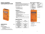
PATTERN GENERATOR PG-V1 USER MANUAL V.2009PGV101.00 Copyright and Trademarks: All rights reserved by C&C TECHNIC TAIWAN CO., LTD. No part of this document may be reproduced in any form or by any means without written permission from the product manufacturer. Changes are periodically made to the information in this document. They will be incorporated in subsequent editions. The product manufacturer may make improvements and /or changes in the product described in this document at any time. All the registered trademarks referred to this manual are belonging to their respective companies. 0 Chapter 1 Introduction ..............................................2 1.1 Package Contents............................................2 1.2 Resolution.......................................................3 1.3 Features ..........................................................3 1.4 Specifications .................................................3 1.5 Front Panel......................................................4 1.6 Side Panel .......................................................5 1.6.1 Video Output Port................................5 1.6.2 HD-15 Connector Pin Definition.........5 1.6.3 Power Jack...........................................5 Chapter 2 Connection ...............................................6 2.1 Preparation......................................................6 2.1.1 Plugs ....................................................6 2.1.2 Plug replacement .................................6 2.2 Connect PG-V1 to Monitor ............................7 Chapter 3 Operation..................................................8 3.1 Starting Status.................................................8 3.2 Power and Battery ..........................................9 3.3 MENU Configurations .................................10 3.3.1 Tim configuration ..............................10 3.3.2 Ptn configuration ...............................10 3.3.3 Sync configuration ............................11 3.3.4 Hky (Hot key) configuration .............13 Chapter 4 Troubleshooting .....................................14 Appendix A................................................................15 Appendix B................................................................18 1 Chapter 1 Introduction PG-V1 is a test pattern generator with VGA connector designed to be a useful tool for the new generation of digital monitor products. PG-V1 supports up to 20 resolutions and 34 patterns for you to test and calibrate a digital monitor. Further, it also can improve the quality of digital monitor with side by side comparisons. Through the friendly interface and smart design, not only you can easy to use the PG-V1 but also you can reduce your test expenditure. Caution To avoid and minimize the risk of damage to PG-V1, please pay attention to the safety instructions even though the PG-V1 had been tested for conformance to safety requirements and certified for international using. Follow all instructions marked on the device during using. Do not attempt to maintain the device by yourself, any faults, please contact your vendor. Provide proper ventilation and air circulation and do not use near water. It is better to keep it in a dry environment. Only using the power adapter and connection cables that are supported with the device. After purchasing and before using the PG-V1 first time, please charge it continuously for more than 16 hours. It is better to charge the battery when the battery power indicator becomes low. The PG-V1 will save the last setting values automatically. Do not use liquid or aerosol cleaners to clean the device. Always unplug the power to the device before cleaning. 1.1 Package Contents 1 VGA pattern generator PG-V1 1 power adapter with DC 12V 1.25A, 4 replaceable plugs (for USA, UK, Europe and Australia DC plugs.) 1 user manual 1 VGA 1.2M cable (HD-15 Male to Male) All packages have been checked carefully for their completeness and functionality before shipped. Please contact with your vendor if any items listed as above are missing or damaged. 2 1.2 Resolution Use for test and calibrating VGA video equipments. Use for test and calibrating VGA image input devices. Use for TV/Monitor product lines. 1.3 Features Intelligent functionality. With 162 MHz pixel frequency. Support total 38 timings. (up to UXGA) Support Sync Type: H/V (TTL), SOG. Low cost. Single interface easily use. Portable design, working time up to 6~8 hours by inside Re-chargeable battery. Auto Power-off on Battery mode. Provide total 34 patterns, Include: Color bar, Gray, Grid, Block… By 16x2 Character LCD and key buttons, easily control. 1.4 Specifications Function PG-V1 Video Output Connector 1 HD-15 Female Select Switch 7 LCD Module: 1 16*2 Character Display Max. Resolution 1600x1200 @ 60 Hz Highest Pixel Frequency 162 MHz Cable Distance 5M Power Adapter (Min.) DC 12V 1.25A Housing Plastic Weight 385 g Dimensions (LxWxH) 190x95x35 mm 3 1.5 Front Panel 1. Video output port 2. LCD Module 3. Function Keys 4. Return 5. Power On/Off 6. Power Jack 2.0ψ 1. Video Output Port: Connect to the attached Video cable. 2. LCD Module: 16*2 Character Display. 3. Function Keys: Depend on the different operation configuration will show you different functions of the keys. 4. “ ” Return: Return to up configuration page. 5. “ ” Power On/Off: Press at least more than 3 seconds to power on/ff the PG-V1. 6. Power Jack: Connect to the DC 12V 1.25A power adapter. 4 1.6 Side Panel 1.6.1 Video Output Port Use for Video cable connector. 1.6.2 HD-15 Connector Pin Definition Pin # Signal Pin # Signal 1 Red video 11 NC 2 Green video 12 NC 3 Blue video 13 Horizontal sync 4 NC 14 Vertical sync 5 Ground 15 NC 6 Analog ground 7 Analog ground 8 Analog ground 9 10 NC Ground 1.6.3 Power Jack Use for the DC 12V 1.25A power adapter. The Power Jack is on the right side of the device. PG-V1 supports 4 replaceable plugs (for USA, UK, Europe and Australia DC plugs.) Power Jack 5 Chapter 2 Connection 2.1 Preparation Caution Please power off the digital monitor and PG-V1 before you begin the connection 2.1.1 Plugs PG-V1 supports you up to 4 replaceable plugs (for USA, UK, Europe and Australia DC plugs.). Please depend on where the location is to exchange the suitable plug. US Plug UK Plug AU Plug EU plug 2.1.2 Plug replacement PG-V1 supports a power adapter DC 12V 1.25A with a plastic ring to protect the connector. Before you to connect the adapter, you have to dismantle the plastic ring firstly. Refer to the pictures as below to dismantle the plastic ring. Caution Please also to pull down the slider to exchange the suitable plug. 6 2.2 Connect PG-V1 to Monitor Monitor/TV Cable or Twins pair Connect the attached DC adapter cable from PG-V1 to the power source (outlet). Connect the VGA cable from PG-V1 to the Monitor/TV. Power on the Monitor/TV. Press the power key of PG-V1 for more than 3 seconds to power on/off the PG-V1. Caution Please power off the Monitor/TV before begin the connection. 7 Chapter 3 Operation )1. After pressing the power On/Off key for 2~3 seconds to sound a long “beep”. 2. Only for the valid key of PG-V1 will sound a short confirmed “beep” after pressing the key. 3. The chosen option will blink. 3.1 Starting Status After you pressing the Power key to power on the PG-V1, the LCD screen will show you the PG-V1 version suddenly then show you the main screen as below (or previous setting values saved in the PG-V1’s memory): P01 640x480 @60 P01: Pattern 01 (refer to Appendix B: Pattern chart) 640x480: Resolution is 640X480 @60: Refresh rate is 60Hz “ ”: The power of battery is charging. To the LCD screen lower left will show you the PG-V1 operated mode just as SOG SOG: Process PG-V1 under SOG mode. H/V: Process PG-V1 under H/V mode. . 8 3.2 Power and Battery The device is suited to the DC 12V 1.25A power adapter and 4 inside Re-chargeable batteries. The signals of PG-V1’s battery on the lower right are described as below: “ ”: The power of battery is charging. “ ”: The power of battery is in full charging. “ ”: The battery is fault. ) 1. When the device stands by for about 39 minutes, it will sound two short “beep”. After the two short “beep” sounds about 1 minute, the device will sound a long “beep” and shout down automatically. 2. When the battery power is lower than 5% just as “ ”, a warming sound “beep” will be heard each second. The sound will continue for 5 minutes, if you don’t get the external power to instead of the internal battery power. The device will shout down immediately. We suggest you it is better to charge the batteries when they are in the lower status. (Before the device shout down, the device will save the last set values including Pattern No., Resolution, Ver. Frequency, P02 Blinking_BLK&WHT No. and Sync_MODE automatically.) 9 3.3 MENU Configurations ) The figures in this chapter are for P01 640x480 @60 mode reference After you power on the PG-V1, please press the MENU indicated key. The MENU configuration screen will be showed as below: 3.3.1 Tim configuration Press the Tim indicated key, the Tim configuration screen will be showed as below: ▼ “▲”: Adjust the Resolution and Refresh Rate with up values. (refer to Appendix A: PG-V1 output signal specification chart) “▼”: Adjust the Resolution and Refresh Rate with down values. (refer to Appendix A: PG-V1 output signal specification chart) “ ”,” ”: Switch between Resolution and Refresh Rate options. ▲ 3.3.2 Ptn configuration Press the Ptn indicated key, the Ptn configuration screen will be showed as below: “▲”: Switch the Pattern mode with up page. (refer to Appendix B: Pattern chart) “▼”: Switch the Pattern mode with down page. (refer to Appendix B: Pattern chart) 10 P02 Blinking mode configuration: Press the set indicated key to enter the black and white setting configuration as below (you can set the black and white blinking frequency (frames/value) here): ▼ “▲”: Increase the BLK or WHT blinking frequency value. The value is up to 255. “▼”: Decrease the BLK or WHT blinking frequency value. “ ”,” ”: Switch between BLK and WHT options. “ ”: Confirm the changed value. ▲ ) 1. Both BLK/WHT are the condensations for Black/White. 2. The bigger Value is set, the lower blinking frequency is supported. 3. When the value is 001, click “▼” indicated key to recycle the 255 value. 3.3.3 Sync configuration Press the Sync indicated key, the Sync configuration screen will be showed as below: a. INFO: Press the INFO indicated key, the Info configuration screen will be showed as below: 11 Hor (Horizontal Frequency Option): Under the Sync/INFO configuration, please press the “ ” to enter the Info/Hor configuration screen including: (Press “▲” and “▼” indicated key to select below items.) Pixel Clock H Sync Polarity Hor Left Border Hor Back Porch Hor Sync Time Hor Front Porch H Right Border Hor Sync Start Hor Blank Time Hor Blank Start Hor Addr Time Hor Total Time Hor Frequency Ver (Vertical Frequency Option): Under the Sync/INFO configuration, please press the “ ” to enter the Info/Ver configuration screen including: (Press “▲” and “▼” indicated key to select below items.) Pixel Clock Vertical Freq Ver Total Time Ver Addr Time Ver Blank Start Ver Blank Time Ver Sync Start V Bottom Border Ver Front Porch Ver Sync Time Ver Back Porch Ver Top Border V Sync Polarity 12 b. MODE: Show you the option for output synchronization is H/V or SOG mode that setting mode will also be showed on the lower left of main screen. 3.3.4 Hky (Hot key) configuration Press the Hky indicated key, the Hky configuration screen will be showed as below: “O”: Represent for “Enable”. “X”: Represent for “Disable”. “R”: Red component output. “G”: Green component output. “B”: Blue component output. “Rev”: Pattern reverse “Out”: Video Output control (On/Off). 13 Chapter 4 Troubleshooting 1. If there is no image when using the PG-V1, please ensure the following matters: a. If it is unable to switch onÆthere is a possibility of fault battery or inferior battery. Please connect it with the transformer. b. If it is able to switch on but there is no imageÆ Lower the resolution or change the resolution and vertical frequency. Please ensure the compatibility of Sync mode: H/V or SOG of the monitor. 2. Which should be care for when using the PG series first time? After purchasing and before using the PG series first time, please charge it continuously for more than 16 hours. 3. What is the Pattern Generator’s function? a. Use to test and maintain studio equipment, such as monitor, cabling, and recording equipment. b. For a TV engineer or technician wants to test and calibrate a DTV monitor during repair. c. A home-theater user wants to get the best results out of the DTV equipment. d. A studio installer wants to test cables and equipment so that can get the best effect. e. For the DTV sets seller to show side by side comparisons of quality. f. For teacher to train their students about the latest DTV quality test technologies. g. To test a new DTV set whether compatibility with the ATSC standards. 4. How to save the changed setting values? The PG series will save the last changed setting values automatically. 5. When should I have to charge the battery? We suggest you to charge the battery when the battery power indicator has become low, it is not appropriate to charge the battery when the battery is consume thoroughly. 14 Appendix A VGA Output Signal Specification Chart: Refresh NO Resolution Rate Pixel Freq (MHz) (Hz) Sync Polarity Hor Ver 1 640x350 85 31.5 P N 2 640x400 85 31.5 N P 3 640x480 60 25.175 N N 4 640x480 72 31.5 N N 5 640x480 75 31.5 N N 6 640x480 85 36 N N 7 720x400 85 35.5 N P 8 800x600 56 36 P P 9 800x600 60 40 P P 10 800x600 72 50 P P 11 800x600 75 49.5 P P 12 800x600 85 56.25 P P 13 848x480 60 33.75 P P 14 1024x768 60 65 N N 15 1024x768 70 75 N N 16 1024x768 75 78.75 P P 17 1024x768 85 94.5 P P 18 1152x864 75 108 P P 19 1280x768 60 RB 68.25 P N 20 1280x768 60 79.5 N P 21 1280x768 75 102.25 N P 22 1280x768 85 117.5 N P 23 1280x960 60 108 P P 15 24 1280x960 85 148.5 P P 25 1280x1024 60 108 P P 26 1280x1024 75 135 P P 27 1280x1024 85 157.5 P P 28 60 85.5 P P 39 1400x1050 60 RB 101 P N 30 1400x1050 60 121.75 N P 31 1400x1050 75 156 N P 32 1600x1200 60 162 P P 33 1920x1200 60 RB 154 P N 1360x768 34 1280x800 60 83.5 N P 35 1366x768 60 80 N N 36 1440x900 60 106.5 N P 37 1440x1050 60 125.25 N N 38 1680x1050 60 146.25 N P RB: Reduced Blanking P: Positive N: Negative 16 Appendix B Pattern chart: 1. FLAT 2. Blinking 3. GRADUALLY 4. GRID_4x3 5. GRID_16x12 6. COLOR_GRID 7. COLORBAR_1 8. COLORBAR_2 9. COLORBAR_3 10. COLORBAR_4 11. GRAY_8 12. GRAY_16 13. GRAY_32 14. GRAY_64 15. DYNAGRAY 16. GRAY_1 17. COLORGRAY64 18. BWSWING 19. BW2SWING 20. WINDOW_1 21. WINDOW_2 22. WINDOW_3 23. WINDOW_4 24. VLINE_1 25. VLINE_2 26. VLINE_3 27. H Pattern_1 28. H Pattern_2 18 29. BLOCK_1 30. BLOCK_4x3 33. HLINE_2 34. HLINE_3 31. BLOCK_16x12 19 32. HLINE_1