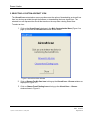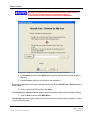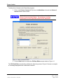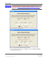
1
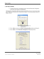
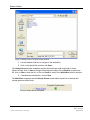
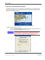
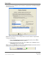
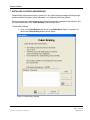
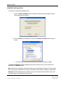
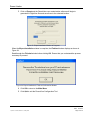
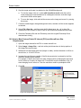
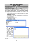
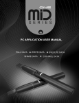
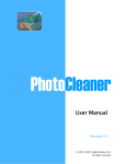
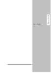
Rosen Aviation
EXTERNAL APPROVAL
REQUIRED
FOR REFERENCE ONLY
RosenView Configuration Tool
User’s Manual
Document Number: 9003384
emplate: 4.2.3-6-FM; Revision A; 16 May, 2005
Revision:
C
Date: 12-28-05
Page 1 of 22
Rosen Aviation
1. REQUIREMENTS
The following requirements must be met in order to customize RosenView Software.
1.1. Operating System Requirements:
z
Windows XP
If problems are encountered while trying to run the Configuration
Tool customization software, ensure that the most current version
of Microsoft .NET Framework is installed on the PC.
The Microsoft .NET Framework install package is available
through a link on the RosenView Configuration Tool CD.
1.2. Human Interface Requirements:
z
PC, Keyboard, and mouse
z
CD ROM
1.3. Hardware Requirements:
z
Available USB Port
z
Minimum 250 Meg free hard drive space
Document Number: 9003384
emplate: 4.2.3-6-FM; Revision A; 16 May, 2005
Revision:
C
Date: 12-28-05
Page 2 of 22
Rosen Aviation
2. GETTING STARTED
1. To start the RosenView customization process, insert the RosenView Configuration
Tool CD into your computer’s CD ROM drive.
The RosenView configuration software should start automatically. If not, use your mouse to open
the CD ROM drive and double click on RosenView Config.exe. The following startup window will
display onscreen:
Figure 1 RosenView Configuration Tool
Startup Window
2. Click on Start to proceed to the Main Customization Menu window (see Figure 2).
3. Click on Quit to exit the RosenView Configuration Tool startup window.
Figure 2 Main Customization Menu Window
Document Number: 9003384
emplate: 4.2.3-6-FM; Revision A; 16 May, 2005
Revision:
C
Date: 12-28-05
Page 3 of 22
Rosen Aviation
3. CREATING A CUSTOM STARTUP SCREEN
The startup screen displays when RosenView is powered on and when there is no flight data
being input to RosenView. Users may change this screen to incorporate their own logo onto the
startup screen or to add aesthetics not offered in the default startup screen.
To change the default startup screen:
1. Click on the Startup Screen link shown in Figure 2 to launch the Startup Screen
window shown below.
Note the Startup Screen window’s listed requirements and
suggestions below. For assistance meeting requirements for best
image quality, see the Appendix section of this document.
Figure 3 Startup Screen Window
2. Click Browse to open the file Open browse window shown in Figure 4.
Note: Ensure that the selection meets the requirements as listed in the Startup Screen
window shown above.
Document Number: 9003384
emplate: 4.2.3-6-FM; Revision A; 16 May, 2005
Revision:
C
Date: 12-28-05
Page 4 of 22
Rosen Aviation
Figure 4 Startup Screen File Open Browse Window
3. Use the Look in: field box to navigate to the desired file.
4. Click on the desired file and then click Open.
The Startup Screen window reappears and the selected image width and height is shown.
Options include: click on Save to change the background image, click on Browse to replace the
file, click on Clear to clear the file, or click on Cancel to return to the Main Menu with no selection.
5. If satisfied with the selection, click on Save.
The Main Menu reappears and the Startup Screen customization check box is checked and
colored green as shown below.
Figure 5 Startup Screen Completed
Document Number: 9003384
emplate: 4.2.3-6-FM; Revision A; 16 May, 2005
Revision:
C
Date: 12-28-05
Page 5 of 22
Rosen Aviation
4. CREATING A CUSTOM BACKGROUND IMAGE
The background image is seen in the margins while viewing RosenView. For example, Figure 6
shows the default light-blue sky with clouds background. Notice the background shows through
RosenView’s top and bottom banners.
Figure 6 Default Background: Light-Blue Sky With Clouds
To replace the default background image:
1. Click on the Background Image link shown in the Main Menu (Figure 2 on page 3) to
launch the Background Image window shown below.
Note the Background Image window’s listed requirements and
suggestions below. For assistance meeting requirements for best
image quality, see the Appendix section of this document.
Figure 7 Background Image Window
Document Number: 9003384
emplate: 4.2.3-6-FM; Revision A; 16 May, 2005
Revision:
C
Date: 12-28-05
Page 6 of 22
Rosen Aviation
2. Click Browse to open the file Open browse window (similar to the window shown in
Figure 4).
3. Use the Look in: field box to navigate to the desired file.
4. Click on the desired file and then click Open.
The Background Image window reappears with options that include: click on Save to change the
background image, click on Browse to replace the file, click on Clear to clear the file, or click on
Cancel to return to the Main Menu with no selection.
5. When satisfied with the background selection, click on Save.
The Main Menu reappears and the Background Image customization check box is checked and
colored green as shown below.
Figure 8 Background Image Customization Completed
Document Number: 9003384
emplate: 4.2.3-6-FM; Revision A; 16 May, 2005
Revision:
C
Date: 12-28-05
Page 7 of 22
Rosen Aviation
5. SELECTING A CUSTOM AIRCRAFT ICON
The Aircraft Icon customization screen provides users the option of downloading an aircraft icon
from icon choices provided through the software, or downloading their own aircraft icon. The
selected icon will represent the aircraft that travels on the map when viewing RosenView.
To select an icon:
1. Click on the Aircraft Icon link shown in the Main Customization Menu (Figure 2 on
page 3) to launch the Aircraft Icon window shown below.
Figure 9 Aircraft Icon Main Window
2. Click on Browse For My Own Icon to bring up the Aircraft Icon – Browse window as
displayed in Figure 10.
3. Click on Choose From Existing Icons to bring up the Aircraft Icon – Choose
window shown in Figure 11.
Document Number: 9003384
emplate: 4.2.3-6-FM; Revision A; 16 May, 2005
Revision:
C
Date: 12-28-05
Page 8 of 22
Rosen Aviation
Note the Custom Aircraft Icon requirements listed in the Aircraft
Icon – Browse window below. For assistance meeting
requirements see the Appendix section of this document.
Figure 10 Aircraft Icon - Browse Window With Default Icon Shown In Example
4. Click Browse to open the file Open browse window (similar to the window shown in
Figure 4).
5. Use the Look in: field box to navigate to the desired file.
Ensure that the selection meets the requirements as listed in the Aircraft Icon – Browse window
shown above.
6. Click on the desired file and then click Open.
The Aircraft Icon – Browse window appears, and the selected image width and height is shown.
7. Click on Save to return to the Main Menu.
The Aircraft Icon customization check box will be checked and colored green as shown in Figure
12 on the following page.
Document Number: 9003384
emplate: 4.2.3-6-FM; Revision A; 16 May, 2005
Revision:
C
Date: 12-28-05
Page 9 of 22
Rosen Aviation
Figure 11 Aircraft Icon - Choose Window
1. Click on an icon from the Icon Choices list box. The image will be displayed under
Preview on the right-hand side of the dialog box.
2. Click on the desired selection, and then click on Save to return to the Main Menu.
The Aircraft Icon customization check box will be checked and colored green as shown below.
Figure 12 Customized Aircraft Icon Completed
6. CUSTOMIZING POINTS OF INTEREST
The Points of Interest (POI) window allows users to include icons and information concerning
areas of interest. Such areas of interest may include personal properties or favorite building
locations. Users have the option of downloading an icon from choices provided through the
software, or downloading their own icon.
Document Number: 9003384
emplate: 4.2.3-6-FM; Revision A; 16 May, 2005
Revision:
C
Date: 12-28-05
Page 10 of 22
Rosen Aviation
To add points of interest to the RosenView program:
1. Click on the Points of Interest (POI) link on the Main Menu to launch the Points of
Interest window shown below.
Note the Custom Icon requirements and information listed in the
Points of Interest window below. For assistance meeting
requirements see the Appendix section of this document.
Figure 13 Points of Interest Window
2. Click the Add button to access the POI Data Editor as seen below in Figure 14.
The POI Data Editor automatically validates the data being entered. Figure 15 shows an example
of a message displayed when invalid data is entered.
Document Number: 9003384
emplate: 4.2.3-6-FM; Revision A; 16 May, 2005
Revision:
C
Date: 12-28-05
Page 11 of 22
Rosen Aviation
To convert latitude and longitude degrees, minutes and seconds to
decimals visit www.fcc.gov/mb/audio/bickel/DDDMMSS-decimal.html on
the web; or search for other conversion sites.
Figure 14 Points of Interest Data Editor
Figure 15 Points of Interest Data Editor With Error Message
3. After completing the POI data input, click Save to return to the Points of Interest
screen as seen in Figure 16.
Document Number: 9003384
emplate: 4.2.3-6-FM; Revision A; 16 May, 2005
Revision:
C
Date: 12-28-05
Page 12 of 22
Rosen Aviation
Figure 16 Points of Interest Window After POI Information is Completed
To add an icon choice for a POI location:
1. Click on the desired location located in the POI Latitude / Longitude table.
2. Complete one of the following two steps:
a. Click Browse to search for custom icons; ensure that icons meet the requirements
as stated in the Points of Interest window.
OR
b. Click on an icon from the Icon Choices list box in the top half of the window and
then click OK.
Custom POI icons will show on the RosenView map when
zoomed in close. As the zoom levels retract, the POI icon will be
replaced by a symbol; from far out zoom levels nothing will show.
Document Number: 9003384
emplate: 4.2.3-6-FM; Revision A; 16 May, 2005
Revision:
C
Date: 12-28-05
Page 13 of 22
Rosen Aviation
The selected icon will be displayed in the POI Latitude / Longitude table on the Points of Interest
screen as shown below.
Figure 17 POI Window With Icon Selected
Repeat this POI procedure to continue adding locations into the POI Latitude / Longitude table.
To change an existing entry:
1. Click on the desired line in the Latitude / Longitude table and then click on Edit to
access the POI Data Editor as seen in Figure 14.
2. When all entry points have been made, click on Save to save, or Cancel to return to
the Main Menu without saving changes.
If Save is chosen, the Main Menu will appear with the Points of Interest customization check box
checked and colored green as shown in as shown below.
Figure 18 Main Menu With POI Option Completed
Document Number: 9003384
emplate: 4.2.3-6-FM; Revision A; 16 May, 2005
Revision:
C
Date: 12-28-05
Page 14 of 22
Rosen Aviation
7. INSTALLING CUSTOM CABIN BRIEFING
Cabin Briefing options allow users to upload up to four cabin briefing messages. Briefings might
include welcome information, travel information, or in-flight services being offered.
These messages are created separate from RosenView and then uploaded to the software. See
file requirements listed in the Cabin Briefing window shown below.
To add cabin briefings:
1. Click on the Cabin Briefing link shown in the Main Menu (Figure 2 on page 3) to
launch the Cabin Briefing window shown below.
Figure 19 Cabin Briefing Window
Document Number: 9003384
emplate: 4.2.3-6-FM; Revision A; 16 May, 2005
Revision:
C
Date: 12-28-05
Page 15 of 22
Rosen Aviation
2. Click Add in the Cabin Briefing window to access the file Open browse window
(similar to the window shown in Figure 4).
3. Using the file Open browse window, find and click on the desired cabin briefing file,
and then click Open.
The Cabin Briefing window will return with the selected file shown in the Briefing table.
Note: To change an existing file, click on an existing file line and then click on Browse to change
the file or Delete to delete the file.
4. Click Add to continue adding Cabin Briefing files.
Figure 20 Cabin Briefing Window With Three Files Added
5. When finished selecting Cabin Briefings, click Save.
The Main Menu appears with the Cabin Briefing customization check box checked and colored
green as shown below.
Figure 21 Cabin Briefing Option Completed
Document Number: 9003384
emplate: 4.2.3-6-FM; Revision A; 16 May, 2005
Revision:
C
Date: 12-28-05
Page 16 of 22
Rosen Aviation
8. EXPORT INSTALLATION
To create the customized installation files:
1. Click on Export Installation when finished customizing selected options and the
following window will appear.
Figure 22 Export Installation Window
2. Click on Browse (if necessary) to access the Browse for Folder window (shown
below).
a. Find and click on the provided thumbdrive’s location and then click OK.
The Export Installation window reappears with the file location shown in the location field
adjacent to the Browse button.
Note: Files can be exported to hard drive locations as well and kept for backup. To reuse these
files, simply copy and paste them to a blank Thumbdrive when ready to install into RosenView.
Warning: The file hierarchy may be saved to any drive, but the file names and file order must
remain the same or RosenView will reject them.
Document Number: 9003384
emplate: 4.2.3-6-FM; Revision A; 16 May, 2005
Revision:
C
Date: 12-28-05
Page 17 of 22
Rosen Aviation
3. Click on Export and the RosenView user customization software will begin to
generate the FlightView files and save them to the selected location.
Figure 23 Export Installation Window In Progress
When the Export Installation window is complete, the Finished window displays as shown in
Figure 24.
Read through the Finished window before clicking OK. Ensure that you understand the process
necessary to proceed.
Figure 24 Export Installation’s Finished Confirmation Window
4. Click OK to return to the Main Menu.
5. Click Quit to exit the RosenView Configuration Tool.
Document Number: 9003384
emplate: 4.2.3-6-FM; Revision A; 16 May, 2005
Revision:
C
Date: 12-28-05
Page 18 of 22
Rosen Aviation
9. CLEARING FILES TO CREATE ANOTHER NEW CONFIGURATION
1. Click on Clear Installation to remove all the currently saved customization files from
the software workspace.
Ensure that saved back-up customization files exist on the hard drive if concerned with losing most
recently customized information.
When Clear Installation is clicked, a New Installation Confirmation window appears as shown
below:
Figure 25 New Installation Confirmation Window
2. Click Yes to clear the file information and start a new installation, or No to cancel.
If a new installation is started, the Main Menu will appear with all customization option check
boxes cleared as shown in Figure 26.
Repeat this document procedure as often as desired to create and save a variety of RosenView
customized options.
Figure 26 Main Menu After Clear Installation
Document Number: 9003384
emplate: 4.2.3-6-FM; Revision A; 16 May, 2005
Revision:
C
Date: 12-28-05
Page 19 of 22
Rosen Aviation
10. APPENDIX
10.1. How to Meet Custom Startup Screen and Background Screen Requirements
This procedure describes how to best create a custom startup screen or background screen to
match RosenView’s 640x480 screen resolution.
The example procedure utilizes Photoshop. If Photoshop is not accessible, other graphics
programs may be used, or download a free trial of Photoshop from the Web
(www.adobe.com/products/photoshop/main.html select tryout under downloads in the leftside column and download Photoshop CS2).
While RosenView can take any image and expand or shrink it to make it fit the required format,
it does not produce good results unless the image is close to a 640x480 screen resolution.
For best results, complete the following steps:
1. The images to be used in the screen may need to be opened and saved in a different
file format so that it can be placed later.
a. To save image(s) in a proper format, open the image(s) with Photoshop, click
FileÆSave As… and save the image as an .EPS file; close the file.
2. Select FileÆ New… to create a new file.
3. Change the settings in the new file as directed in the image below:
Change this setting
to 640.
Change this setting
to 480.
Leave settings
as pixels
Change the resolution
to 300
Change contents to
background color
Figure 27 Change settings for the new startup screen
4. Click OK and the new file will open; select ViewÆFit on Screen in the main toolbar.
5. Select FileÆPlace…
a. Browse for and select an image for the custom screen, and then click on Place.
Document Number: 9003384
emplate: 4.2.3-6-FM; Revision A; 16 May, 2005
Revision:
C
Date: 12-28-05
Page 20 of 22
Rosen Aviation
6. Size the image and locate it as desired on the 640x480 background.
a. To size the image, click on it, select editÆtransformÆscale, and click on the
corner and drag to scale as desired; for a background screen, scale the image
such that it fills the entire space.
b. To move the image, click and hold the mouse on the image and move it by moving
the mouse.
7. Continue to add images, change background colors, etcetera until the screen appears
as desired.
8. Select FileÆSave As… and then save the file format as a .jpg, .gif, or .bmp file;
remember the file location to select it later in the RosenView customization process.
9. Close the Photoshop file and exit Photoshop; save the original Photoshop file as
desired when closing.
10.2. How to Meet Custom Points Of Interest (POI) and Aircraft Icon Size
Requirements
1. Open the image desired for the POI or custom aircraft icon.
2. Select ImageÆ Image Size… and look at the pixel dimensions in the top portion of
the Image Size menu screen.
3. Whichever has the highest pixel size (height or width), set that dimension to 40 for an
aircraft icon, or 16 for a POI icon.
4. Increase the resolution as possible; if the file document size is reduced by half, the
resolution setting can be doubled.
For example, if the file document size were changing (due to changing the pixel size)
from 4 inches to 2 inches, an image with 72 resolution could be doubled to 144. If it
were changing from 4 inches to 1 inch the resolution could be quadrupled to 288.
5. Click OK.
Change the higher of
the two listed pixel
values as directed in
step 3.
Figure 28 Height Set to 480
Document Number: 9003384
emplate: 4.2.3-6-FM; Revision A; 16 May, 2005
Revision:
C
Date: 12-28-05
Page 21 of 22
Rosen Aviation
6. Select FileÆSave As… and then save the file format as a .jpg, .gif, or .bmp file;
remember the file location to select it later in the RosenView customization process.
7. Close the Photoshop file and exit Photoshop; save the original Photoshop file as
desired when closing.
Document Number: 9003384
emplate: 4.2.3-6-FM; Revision A; 16 May, 2005
Revision:
C
Date: 12-28-05
Page 22 of 22