1
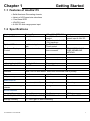
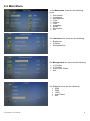
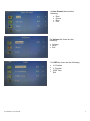
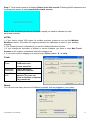
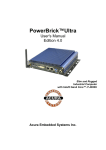
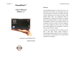
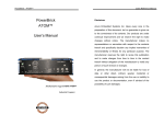
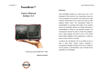
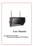
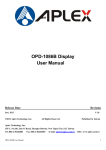
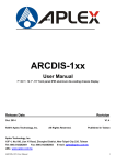
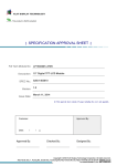
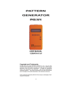
AcuDis115 User Manual , Acura Embedded Systems Inc. Table of Contents_____________________ Chapter 1 Getting Started 1.1 1.2 1.3 1.4 1.5 Features of AcuDis115...…………………………………………………….1 Specifications………………………………………….......……..……….….1 Dimensions…………………………………...…………………..……….…2 Brief Description ……………..……………………...........................…….3 Display Mode………………………………………………………………....3 Chapter 2 OSD 2.1 2.2 2.3 2.4 AD Board OSD Functions………………………….…..……………….…...4 OSD Controls………………..…..…………………………………………....5 OSD Default Parameter…..……………………………………………….....5 Main Menu……………………………………………………………….....…6 Chapter 3 Installation 3.1 Introduction to the PenMount 9036 Controller Board………….….……....9 3.2 Windows 2000/XP/2003/Vista Universal Driver Installation for PenMount 6000 Series…………………………………………………………....……….9 3.3 Installing Software……………………………………………….......………..9 3.4 Software Functions……………………………………………….....……….11 ACUDIS115 User Manual I Chapter 1 Getting Started 1.1 Features of AcuDis115 • • • • • Solid Aluminum Die-casting chassis Variety of LCD panel size selections Front bezel IP65 VGA/DVI input 9~36V DC wide range power input 1.2 Specifications Hardware Default I/O Port : Display Type 1 x VGA 1 x DVI Option I/O Port : On Screen Display Control 1 x Line in by phone jack On board controller 15” 1024 TFT LCD 1 x USB for Touch control 1 x Tack switch for VGA / DVI transform 1 x DB-9 for Resistive Touch control extendable key pay from connector 1 x 3 pins terminal block power input 9~36V DC TRANSFER BOARD OSD MEMBRANE KEYPAD LCD Max. Resolution 1024x768 Max. Color 16.2 M Luminance (cd/m²) 350 Viewing Angle (H/V) 160°/145° Backlight Lifetime 50,000 hrs Power Input 9~36V DC on board Contrast Ratio 800:1 Touch Screen Interface USB / RS-232 auto detect, when both connected USB is primary Type Projected Capacitive Interface USB interface on tail Light Transmission Construction Dimensions (WxHxD) Net Weight Mounting Aluminum Die-casting chassis 410x310x55 mm 4.3 kg Panel / VESA 100x100 Over 90% Mechanical Environment Operating Temperature Storage Temperature 0 ~ 50 ℃ (32 ~ 122 ℉) Certificate -20 ~ 60 ℃ (-4 ~ 140 ℉) CE/FCC Class A Storage Humidity 10 ~ 90% @40℃ Non-condensing ACUDIS115 User Manual IP Rating Front Panel IP65 1 1.3 Dimensions Figure 1.4: Dimensions of AcuDis115 ACUDIS115 User Manual 2 1.4 Brief Description AcuDis115 is a total IP65 aluminum front bezel and chassis LCD Display, which comes with a 15 inch (luminance of 350 cd/m²) TFT LCD. AcuDis115 comes with a viewing angle of 160 (H) degrees and 145 (V) degrees. AcuDis115 has more outstanding features, thus giving you the best in monitoring and control applications. AcuDis115 can be VESA-100 mounted . 1.5 Display Mode Resolution H Freq.(kHz) Figure 2.2: Front View of AcuDis115 V Freq.(Hz) Remark 640x350@70 31.469 70.087 VGA 640x400@70 31.469 70.087 VGA 640x480@66 35.000 66.667 MAC 640x480@72 37.861 72.809 VESA 720x400@70 31.469 75.000 TEXT 800x600@56 35.156 56.250 VESA 800x600@72 48.077 72.188 VESA 832x624@75 49.107 75.087 MAC 848x480@60 31.020 60.000 VESA 1152x864@70 63.850 70.000 VESA 1152x864@75 67.500 75.000 VESA 1152x900@76 71.809 76.149 SUN 1280x960@60 60.000 60.000 VESA 1440x900@60 56.040 60.000 VESA 1440x1050@60 65.320 59.980 VESA 1440x1050@75 82.280 74.870 VESA Figure 2.3: Rear View of AcuDis115 ACUDIS115 User Manual 3 Chapter 2__________________OSD _______ 2.1 AD Board OSD Functions Auto Adjust Up/Left Down/Right Power Menu/Entry Power Indicator Power switch: To turn ON or OFF the power Shift the icon to the right side or shift it up Shift the icon to the left side or shift it down Menu: To enter OSD menu for related icon and item. Auto Button: One-touch auto adjustment 1.) Getting into Burn-in Mode Before setting into a burn-in mode, first disconnect the AC power cord. Then press (don’tlet them go) the buttons until the AC power cord is connect of your screen. Now it can be put into the burn-in mode for changing colors. 2.) Getting Out of Burn-in Mode Before getting out of the burn-in mode, please first disconnect the AC power cord. Then press the button (If not workable, press the button and don’t let them go) until the AC power cord is connected. Please don’t let your fingers go until the AC power cord is connected again and the wording of “RGB” appears on the top left corner of your screen, and wait for 3 second. Under the non-signal entry situation, if ACUDIS115 User Manual Cable Not Connected is seen, exit is thus successfully made. 4 When the Burn-in Mode is Unable to Eradicate… 1.) If the “RGB” is still on the top left corner of the screen, press choose “Reset”, and then Yes, and press to enter “Miscellaneous” and . When the screen goes black, disconnect power and repeat the above steps. buttons 2.) If the “RGB” is not found, disconnect the AC power cord first. Then press the (don’t let them go) until the AC power cord is connected, and wait for 2 to 3 seconds. When “RGB” appears, repeat the above steps. 3.) Functions of OSD Keys 2.2 OSD Controls To make any adjustment, select the following: 1. Press (Menu) to show the OSD menu or disable the OSD menu. 2. Select the icon that you wish to adjust with the ( / 3. Press (Menu) and then choose the item with the ( 4. Press (Menu) and then adjust the quality with the ( or +/-) key in the menu. or +/-) key. / / 4.) If the “RGB” is still on the top left corner of the screen, press choose “Reset”, and then Yes, and press or +/-) key. to enter “Miscellaneous” and . When the screen goes black, disconnect power and repeat the above steps. 5.) If the “RGB” is not found, disconnect the AC power cord first. Then press the buttons (don’t let them go) until the AC power cord is connected, and wait for 2 to 3 seconds. When “RGB” appears, repeat the above steps. 6.) Functions of OSD Keys 2.3 OSD Default Parameter Management Luminance Blue 80 Language English H. Position auto Brightness 70 Red 80 V. Position auto Contrast 50 Green 80 H. Position Auto Pixel Clock auto Sharpness 3 Mute ON V. Position Auto Phase auto Color 6500 Volume 50 OSD time Auto ACUDIS115 User Manual OSD 5 2.4 Main Menu In the Main menu, there are the following items: Auto Adjust Luminance Management Color Volume OSD Language Recall Information Exit For Luminance list, there are the following: Brightness Contrast Sharpness Exit For Management list, there are the following: H. Position V. Position Pixel Clock Phase Exit For Color list, there are the following: • 9300 • 6500 • 5400 • User Preset • Exit ACUDIS115 User Manual 6 In User Preset, there are the following: • • • • Red Green Blue Exit For Volume list, there are the following: • • • Volume Mute Exit For OSD list, there are the following: ACUDIS115 User Manual H. Position V. Position OSD Time Exit 7 For Language list, there are the following: • • • • • • • • • • • English Francais Deutsch Italiano Espanol 日本語 繁體中文 简体中文 Portuguese 한국의 Pусский For Recall list, there are the following: • • • Recall Color Recall All Exit For Information list, there are the following: • • ACUDIS115 User Manual Display Information Exit 8 Chapter 3___________________ Installation 3.1 Introduction to Touch Screen Controller Board AcuDis115's touch screen is PenMount 6300 USB control board which is designed for USB interface and specific for 4, 5, 8-wire touch screens. It is designed with USB interface features with multiple devices supporting function. PenMount 6300 control board using PenMount 6000 controller that has been designed for those who may like and all-in-one solution with 10-bit A/D converter built-in to make the total printed circuit board denser, circuit diagram also designed for 12-bit ADC for optional. There are two connectors on this board, one connector is for 4, 5, 8-wire touch screen cable (optional), and another is for 4-pin USB A type cable (optional). 3.2 Windows 2000/XP/2003/Vista Universal Driver Installation for PenMount 6000 Series Before installing the Windows 2000/XP driver software, you must have the Windows 2000/XP system installed and running on your computer. You must also have one of the following PenMount 6000 series controller or control boards installed: PM6500, PM6300. 3.3 Installing Software If you have an older version of the PenMount Windows 2000/XP driver installed in your system, please remove it first. Follow the steps below to install the PenMount DMC6000 Windows 2000/XP driver. Step 1. Please make sure your PenMount 6000 device had plugged in advance. If your device uses RS232 interface, please plugged in before the machine is turned on. When the system first detects the controller board, a screen appears that shows “Unknown Device”.Do not use this hardware wizard. Press Cancel. ACUDIS115 User Manual 9 Step 2. Insert the product CD install setup.exe. Click touch panel driver Step 3. A License Agreement appears. Click IAgree“…” and Next”“ Step 4. Choose the folder in which to install PenMount Windows Universal Driver. Click Install. Step 5. Wait for installation. Click Next to continue. Step 6. Click OK. Step 7. Click Finish to complete installation. ACUDIS115 User Manual 10 3.4 Software Functions Upon rebooting, the computer automatically finds the new 6000 controller board. The touch screen is connected but not calibrated. Follow the procedures below to carry out calibration. 1. After installation, click the PenMount Monitor icon “PM” in the menu bar. 2. When the PenMount Control Panel appears, select a device to “Calibrate.” PenMount Control Panel The functions of the PenMount Control Panel are Device, Multiple Monitors, Tools and About, which are explained in the following sections. Device In this window, you can find out that how many devices are detected on your system. Calibrate This function offers two ways to calibrate your touch screen. ‘Standard Calibration’ adjusts most touch screens. ‘Advanced Calibration’ adjusts aging touch screens. Standard Calibration Click this button and arrows appear pointing to red squares. Use your finger or stylus to touch the red squares in sequence. After the fifth red point calibration is complete. To skip, press ‘ESC’. Advanced Calibration Advanced Calibration uses 4, 9, 16 or 25 points to effectively calibrate touch panel linearity of aged touch screens. Click this button and touch the red squares in sequence with a stylus. To skip, press ESC’. ACUDIS115 User Manual 11 Command Calibration Command call calibration function. Use command mode call calibration function, this can uses Standard, 4, 9, 16 or 25 points to calibrate E.g. Please run ms-dos prompt or command prompt c:\Program Files\PenMount Universa Driver\Dmcctrl.exe -calibration 0 ( Standard Calibration) Dmcctrl.exe - calibration ($) 0= Standard Calibration 4=Advanced Calibration 4 9=Advanced Calibration 9 16=Advanced Calibration 16 25=Advanced Calibration 25 Step 1. Please select a device then click “Configure”. You can also double click the device too. Step 2.Click “Standard Calibration” to start calibration procedure ACUDIS115 User Manual 12 NOTE: The older the touch screen, the more Advanced Mode calibration points you need for an accurate calibration. Use a stylus during Advanced Calibration for greater accuracy. Please follow the step as below: Step 3.Come back to “PenMount Control Panel” and select “Tools” then Click “Advanced Calibration”. ACUDIS115 User Manual 13 Select “Device” to calibrate, then you can start to do “Advanced Calibration”. NOTE: Recommend to use a stylus during Advanced Calibration for greater accuracy. ACUDIS115 User Manual 14 Setting About This panel displays information about the PenMount controller and driver version. ACUDIS115 User Manual 15 Multiple Monitors Multiple Monitors supports from two to six touch screen displays for one system. The PenMount drivers for Windows 2000/XP support Multiple Monitors. This function supports from two to six touch screen displays for one system. Each monitor requires its own PenMount touch screen control board, either installed inside the display or in a central unit. The PenMount control boards must be connected to the computer COM ports via the RS-232 interface. Driver installation procedures are the same as for a single monitor. Multiple Monitors supports the following modes: Windows Extend Monitor Function Matrox DualHead Multi-Screen Function nVidia nView Function NOTE: The Multiple Monitors function is for use with multiple displays only. Do not use this function if you have only one touch screen display. Please note once you turn on this function the Rotating function is disabled. Enable the multiple display function as follows: Step 1. Check the Multiple Monitor Support box; then click Map Touch Screens to assign touch controllers to displays. Step 2. When the mapping screen message appears, click “OK” ACUDIS115 User Manual 16 Step 3. Touch each screen as it displays Please touch this monitor Following.this Pr sequence and touching each screen is called mapping the touch screens. Step 4. After the setting procedure is finished, maybe you need to calibrate for each panel and controller NOTES: 1. If you used a single VGA output for multiple monitors, please do not use the Multiple Monitors function. Just follow the regular procedure for calibration on each of your desktop monitors. 2. The Rotating function is disabled if you use the Multiple Monitors function. 3. If you change the resolution of display or screen address, you have to redo Map Touch Screens so the system understands where the displays are. 4. If you more monitor mapping one touch screen, Please press ‘S’ to skip Tools Draw Tests or demonstrates the PenMount touch screen operation. Advanced Calibration Right Button Icon Enable Advanced Calibration function Enable right button function. The icon can show on Desktop or System Tray (menu bar). About You can see how many devices of PenMount controller that are plugged to your system ACUDIS115 User Manual 17 PenMount Monitor Menu Icon The PenMount monitor icon (PM) appears in the menu bar of Windows 2000/XP system when you turn on PenMount Monitor in PenMount Utilities. PenMount Monitor has the following function PenMount Rotating Functions The PenMount driver for Windows 2000/XP supports several display rotating software packages. Windows Me/2000/XP support display rotating software packages such as: •Portrait’s Pivot Screen Rotation Software •ATI Display Driver Rotate Function •nVidia Display Driver Rotate Function •SMI Display Driver Rotate Function •Intel 845G/GE Display Driver Rotate Function Configuring the Rotate Function 1. Install the rotation software package. 2. Choose the rotate function (0°, 90°, 180°, 270°) in the 3rd party software. The calibration screen appears automatically. Touch this point and rotation is mapped. NOTE: The Rotate function is disabled if you use Monitor Mapping ACUDIS115 User Manual 18 With the unique set of products, Acura Embedded Systems remains committed to its goal of providing troublefree and customer-friendly service. A special customer service unit has been set up specifically to cater to our esteemed customers' needs. Technical Support: North American Technical support contact your Salesperson Toll Free : 1-866-528-2214 [email protected] Mailing address: Acura Embedded Systems Inc. Unit #1, 7711-128th Street, Surrey, BC V3W 4E6, CANADA Ph: (604) 502-9666 Fax: (604) 502-9668 www.acuraembedded.com