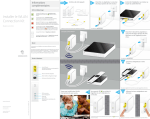
1
SCORPIO 23’
User’s manual
SERVICEVISION BIS SL
Ríos Rosas, 20 · 08940 CORNELLÀ DE LLOBREGAT (Barcelona) Spain · Tel. 34 93 223 86 30 · Fax 34 93 223 86 31
[email protected] · www.servicevision.es
1
INDEX
A-. Description…………………………………………………………………………………3
B-. Parts, components and functions...……………………………………………………..5
B1-. Dolly…………………………………………………………………………………..…6
B1.1 Track Wheels……………………………………………………………………..…9
B1.2 Pneumatic Wheels…………………………………………………………………11
B1.3 Leveling Jacks…………………………………………………..…….……………13
B1.4 Steering………………………………………………………………………….…..15
B1.5 Push Bar Support……………………………………………………………..……16
B1.6 Wheel Arm Position………………………………………………….……..………18
B2-. Telescopic column………………………………………………………………….…22
B2.1 Process to telescope the Column……………………………………...…………24
B3-. Fulcrum………………………………………………………………………………...26
B4-. The Crane Arm……………………………………………………….…………….…29
B4.1-. The tubes……………………………………………………………………….…31
B4.1.1 The Main Tube ………………………………………………….……….……31
B4.1.1.1 Crane Arm Fixation Guides……………………………..………….……33
B4.1.1.2 Protection bars……………………………………….……………………35
B4.1.2 Telescopic Tubes……………………………………………….…………..…36
B4.1.2.1 Hanging the Cable Looms …………………………………….…..……38
B4.2-. Conter Weight Holder……………………………………………………………41
B4.2.1 Front and Back Counter Weight Holders………………………. ……….…42
B4.2.2 The Sliding Weight……………………………………………………….……43
B4.2.3 The Moving Weight Carriage……………………………..…….……………44
B4.2.4 The Counter Weight…………………………………………….………..……46
B4.2.5 Balancing the crane ………………………….…………………….…………48
B4.2.5.1 The Static Balancing…………..……………………….…………………48
B4.2.5.2 The Dynamic Balancing……………………………………………..……48
B5-. The Electronic Control Box…………………………………………..………………50
B5-.1 Functions………………………………………………………..……………….…56
B5.1.1 Start up Prodecure …………………………………………………….…...…56
B5.1.2 Settings “Settings”………………………..……………………………………60
B5.1.3 Límits“Limits”………………………………………………….……………..…68
B5.1.4 The Arc Compensator “Arc Comp”……………………………….……….…69
B5.1.5 Dynamic Counter Weight System Generator“CWE Gen”……………....…70
B5.1.6 Motion Generator“MOTION GENERATOR”……………………………..…70
B5.1.7 Sequential Limits “STOP SEQUENCE”…………………….……….………73
B5.2 Hand command…………………………………………………….………………76
B6-. Leveling Head……………………………………..………………….……….…...... 78
SERVICEVISION BIS SL
Ríos Rosas, 20 · 08940 CORNELLÀ DE LLOBREGAT (Barcelona) Spain · Tel. 34 93 223 86 30 · Fax 34 93 223 86 31
[email protected] · www.servicevision.es
2
A-. Description.
The SCORPIO 23´ is a 7, 1 meter/ 23 foot telescopic crane. It has a telescopic
arm range of 5, 5 meters/ 15 feet.
The crane arm is made of aluminium. It has 4 steel guides and two independent
cables per tube. This provides smoother and quieter movement.
It has an electronic box which gives enough power to run the crane with a
maximum controlled speed of “1,2m/s”. Added features are: adjustable damping,
electronic arm limits, an arc compensator, a motion generator, output encoder
information, crane arm length and height, a stop sequence program and other
information on a display screen.
It has a levelling head which is mounted at the end of the telescopic arm. The
levelling head maintains the horizon in all positions for the Remote Camera Head.
Techincal especifications.
-Weight: 600 kg. / 1322.8 lb.
- Max. weight: 1100 kg./ 2425 lb.
- Arm weight: 255 kg. / 562.2 lb.
- Fulcrum weight: 31.9 kg. / 70.3 lb
- Dolly weight: 188.5 kg / 415.6 lb.
- Max payload underslung: 70 kg / 154.3 lb.
- Max.payload overslung: 30kg. / 66.1 lb
- Max speed:1,2 m/s
- Arm lenght: 7,1m. / 23 ft.
- Telescopic range: 5.6m. / 15 ft.
- Rear lenght: 1.8m / 6 ft.
SERVICEVISION BIS SL
Ríos Rosas, 20 · 08940 CORNELLÀ DE LLOBREGAT (Barcelona) Spain · Tel. 34 93 223 86 30 · Fax 34 93 223 86 31
[email protected] · www.servicevision.es
3
SERVICEVISION BIS SL
Ríos Rosas, 20 · 08940 CORNELLÀ DE LLOBREGAT (Barcelona) Spain · Tel. 34 93 223 86 30 · Fax 34 93 223 86 31
[email protected] · www.servicevision.es
4
B-. Parts, components and functions.
B6 Leveling head
B4.2.3. Counterweight
B1 Dolly
B2 Column
B5 Electronic Box
B3 Fulcrum
B4 Arm
SERVICEVISION BIS SL
Ríos Rosas, 20 · 08940 CORNELLÀ DE LLOBREGAT (Barcelona) Spain · Tel. 34 93 223 86 30 · Fax 34 93 223 86 31
[email protected] · www.servicevision.es
5
B1-. Dolly.
The SCORPIO 23´ has a dolly with adjustable wheel arms and four levelling jacks.
The adjustable wheel arms have three positions allowing us to use both 62cm. / 2ft.
and 1m. / 3.3 ft tracks. This also gives us a major manuverability advantage as we
can pass trough a regular 80cm. / 2.6 ft. doorway.
Its two independent steering handles and pneumatic wheels allow us to move the
crane through tight corners.
Descripción:
- Lenght: 1715 mm. / 5.6’
- Widght: 1345 mm. / 4.4‘
- Height: 502 mm. / 1.6’
- Weight: 188.5 kg. / 415.5 lb.
Steering wheel
Leveling jacks
Steering handles
Pneumatics
wheels
Track wheels
SERVICEVISION BIS SL
Ríos Rosas, 20 · 08940 CORNELLÀ DE LLOBREGAT (Barcelona) Spain · Tel. 34 93 223 86 30 · Fax 34 93 223 86 31
[email protected] · www.servicevision.es
6
Pushing arm supports
Leveling jacks
support
Steering track
pin locker
Straps rings
Wheel arms
locker
Column support
guide
SERVICEVISION BIS SL
Ríos Rosas, 20 · 08940 CORNELLÀ DE LLOBREGAT (Barcelona) Spain · Tel. 34 93 223 86 30 · Fax 34 93 223 86 31
[email protected] · www.servicevision.es
7
Three possibles dollie’s configurations.
-62 cm. / 2 ft. track
- 100 cm. / 3.3 ft. track
- Smaller position, only for go through a door.
SERVICEVISION BIS SL
Ríos Rosas, 20 · 08940 CORNELLÀ DE LLOBREGAT (Barcelona) Spain · Tel. 34 93 223 86 30 · Fax 34 93 223 86 31
[email protected] · www.servicevision.es
8
B1.1 Track wheels.
The SCORPIO 23´ has quick put on/take off tracking wheels for tracking shots.
These tracking wheels are designed to eliminate the memory effect.
Track wheels
secured
Track wheels
Track wheel’s
break
The tracking wheels can be fixed on the dolly while transporting it, but we
recommend removing and storing them when not in use.
To fix or remove the tracking wheels they are fastened to the bottom of the dolly,
next to the pneumatic wheels, with a direction positioner and locking screw.
The tracking wheels must be mounted with their brake facing outwards.
SERVICEVISION BIS SL
Ríos Rosas, 20 · 08940 CORNELLÀ DE LLOBREGAT (Barcelona) Spain · Tel. 34 93 223 86 30 · Fax 34 93 223 86 31
[email protected] · www.servicevision.es
9
You must keep that there are two kinds of track wheels. One of them can
move the axial part, and the other one is fixed. This characteristic is used
to adjust correctly the dolly with the tracks. It’s important that the same kind
has to be assembled at the same dolly’s side.
Fixed axis
Moving axis
SERVICEVISION BIS SL
Ríos Rosas, 20 · 08940 CORNELLÀ DE LLOBREGAT (Barcelona) Spain · Tel. 34 93 223 86 30 · Fax 34 93 223 86 31
[email protected] · www.servicevision.es
10
B1 Pneumatic Wheels.
The pneumatic wheels always have to be on the dolly. They are only allowed to
be removed when the crane is on tracks.
Especifications:
- Inflated with air 2-2.5 bar.
- Ref. 145/80R10 69S
Pneumatic wheel
Pneumatic’s break
Bushing
wheel
Castle nut
Castle key
Help bar
SERVICEVISION BIS SL
Ríos Rosas, 20 · 08940 CORNELLÀ DE LLOBREGAT (Barcelona) Spain · Tel. 34 93 223 86 30 · Fax 34 93 223 86 31
[email protected] · www.servicevision.es
11
Pneumatic wheel
Pneumatic’s break
Wheel
bushing
Castle nut
To remove the wheels they must be lifted from the ground with their respective
levelling jack. The brake must be off. With the castle tool unscrew the nut that fixes
the wheel to the dolly. Then with two hands remove the wheel from the wheel
bushing.
1
2
3
To fix the wheel again, do the same operation fixing the castle nut with your hands
only.
SERVICEVISION BIS SL
Ríos Rosas, 20 · 08940 CORNELLÀ DE LLOBREGAT (Barcelona) Spain · Tel. 34 93 223 86 30 · Fax 34 93 223 86 31
[email protected] · www.servicevision.es
12
B1.3 Leveling jacks.
For transport and normal use of the crane without tracks, the levelling jacks must
always be mounted on the dolly.
The levelling jacks have two locations: mounted on the outside of the pneumatic
wheels or in the their holders located on the dolly.
Steering wheel
Leveling jack
SERVICEVISION BIS SL
Ríos Rosas, 20 · 08940 CORNELLÀ DE LLOBREGAT (Barcelona) Spain · Tel. 34 93 223 86 30 · Fax 34 93 223 86 31
[email protected] · www.servicevision.es
13
• Leveling’s assembly.
Bushing wheel
Leveling jack
Gold locking pin
To fix them onto the wheels slide them into the tube that comes out of the wheel
bushing and lock them in place with the gold locking pin. To do this operation the foot
of the levelling jack must not touch the ground.
1
2
3
4
SERVICEVISION BIS SL
Ríos Rosas, 20 · 08940 CORNELLÀ DE LLOBREGAT (Barcelona) Spain · Tel. 34 93 223 86 30 · Fax 34 93 223 86 31
[email protected] · www.servicevision.es
14
B1.4 Steering.
For transport and normal use the crane´s steering handles must always be locked
with the locking pins. Only remove the locking pin when you need to use the
steering.
When you remove the locking pin, put it in its support on the dolly.
The dolly has two independent steering handles, one for each set of wheels, front
and back.
It is possible to use them both independently or together if you need to make a
tight corner.
Steering handles
Steering handles
Steering
locking pin
SERVICEVISION BIS SL
Ríos Rosas, 20 · 08940 CORNELLÀ DE LLOBREGAT (Barcelona) Spain · Tel. 34 93 223 86 30 · Fax 34 93 223 86 31
[email protected] · www.servicevision.es
15
B1.5 Push Bar Support
The push bar clamps are situated on both sides of the dolly. Standard 50 mm. tubes
can be mounted to push the dolly on tracks.
Push bar clamps
SERVICEVISION BIS SL
Ríos Rosas, 20 · 08940 CORNELLÀ DE LLOBREGAT (Barcelona) Spain · Tel. 34 93 223 86 30 · Fax 34 93 223 86 31
[email protected] · www.servicevision.es
16
• Possible assembly.
SERVICEVISION BIS SL
Ríos Rosas, 20 · 08940 CORNELLÀ DE LLOBREGAT (Barcelona) Spain · Tel. 34 93 223 86 30 · Fax 34 93 223 86 31
[email protected] · www.servicevision.es
17
B1.6 Wheel Arm Position
The SCORPIO 23´ has three wheel arms positions. This allows us to use 62cm / 2 ft.,
and 1m. / 3.3 ft., tracks and allows us to pass through a standard 80cm. / 2.6 ft.
doorway.
Option A is for 1m. / 3.3 ft. wide tracks and high speed movements. It is the widest
and therefore makes the crane most stable.
The option B is for 62cm / 2 ft. wide tracks and normal speed movements.
SERVICEVISION BIS SL
Ríos Rosas, 20 · 08940 CORNELLÀ DE LLOBREGAT (Barcelona) Spain · Tel. 34 93 223 86 30 · Fax 34 93 223 86 31
[email protected] · www.servicevision.es
18
The option C is the narrowest and is used to pass the crane through doorways. In
this configuration it is forbidden to use the crane to shoot. The base is not stable
enough to allow arm movement. The crane is top heavy and will topple over. The
steering can only turn a few degrees in either direction because of the width of
the wheel arms.
All three configurations can be used for transportation.
SERVICEVISION BIS SL
Ríos Rosas, 20 · 08940 CORNELLÀ DE LLOBREGAT (Barcelona) Spain · Tel. 34 93 223 86 30 · Fax 34 93 223 86 31
[email protected] · www.servicevision.es
19
• How to change the positon.
Fasten the crane arm with it´s straps to change the configuration of the wheel arms.
It is not necessary to remove the counterweights.
The four levelling jacks have to be mounted on the wheels.
Lift the dolly with all the levelling jacks except the respective wheel´s until you can
move the respective wheel´s arm. Be careful as the crane is slightly unstable during
the operation.
Remove the screw that holds the wheel arm in place with the 24mm ratchet
spanner.
1
SERVICEVISION BIS SL
Ríos Rosas, 20 · 08940 CORNELLÀ DE LLOBREGAT (Barcelona) Spain · Tel. 34 93 223 86 30 · Fax 34 93 223 86 31
[email protected] · www.servicevision.es
2
20
Using your hands move the wheel arm to the new position and fix the screw back in
place.
3
4
Lower the levelling jacks until the wheel touches the ground. Repeats the same
operation with the three other wheel arms.
SERVICEVISION BIS SL
Ríos Rosas, 20 · 08940 CORNELLÀ DE LLOBREGAT (Barcelona) Spain · Tel. 34 93 223 86 30 · Fax 34 93 223 86 31
[email protected] · www.servicevision.es
21
B2-. Telescopic column.
The SCORPIO 23´arm is supported by a 90 cm / 3ft. high column. This column is
made up of a main column with a telescopic section inside it. It can be raised 40cm /
1.3ft.. This can be done with a 1kW. drilling machine.
The column has a flat base. It can therefore be fixed to any properly designed structure
on a camera car etc.
Fulcrum base
Column’s break
bolts
Strap rings
Visual guide for
telescopic elevation
mark
Acces for the
lubrication
Telescopic column
Bolt (24 mm.)
Flat base
SERVICEVISION BIS SL
Ríos Rosas, 20 · 08940 CORNELLÀ DE LLOBREGAT (Barcelona) Spain · Tel. 34 93 223 86 30 · Fax 34 93 223 86 31
[email protected] · www.servicevision.es
22
Column’s sketch:
Hole support
guide
SERVICEVISION BIS SL
Ríos Rosas, 20 · 08940 CORNELLÀ DE LLOBREGAT (Barcelona) Spain · Tel. 34 93 223 86 30 · Fax 34 93 223 86 31
[email protected] · www.servicevision.es
23
B2.1 Process to telescope the Column
To elevate the column the arm can be loaded or unloaded.
Remove the arm straps, fix the pan and tilt brakes and loosen the four column
bolts.
Telescopic column
bolt
At the bottom of the base there is a 24mm nut which is mechanically linked to
the telescopic column. Use it to raise and lower the column.
It is possible to use the ratchet spanner provided or an electrical drilling
machine (1kW.) with the adaptor provided.
SERVICEVISION BIS SL
Ríos Rosas, 20 · 08940 CORNELLÀ DE LLOBREGAT (Barcelona) Spain · Tel. 34 93 223 86 30 · Fax 34 93 223 86 31
[email protected] · www.servicevision.es
24
Use the two guide lines marked on the telescopic column to know where the
maximum and minimum heights are.
Visual guide
mark
When you have finished tighten the four column bolts again.
SERVICEVISION BIS SL
Ríos Rosas, 20 · 08940 CORNELLÀ DE LLOBREGAT (Barcelona) Spain · Tel. 34 93 223 86 30 · Fax 34 93 223 86 31
[email protected] · www.servicevision.es
25
B3-. Fulcrum.
The SCORPIO 23´ s arm is supported on the Column by the Fulcrum.
A Panoramic or Tilt motion is made via the Fulcrum. The Pan and Tilt brakes are
situated on the Fulcrum.
The arms of the Fulcrum are of different widths so that the correct mounting
position of the Crane Arm is evident.
Wide Fulcrum Support
Tilt Encoder
Pan Encoder
Narrow Fulcrum Support
Tilt Brake
Pan Brake
SERVICEVISION BIS SL
Ríos Rosas, 20 · 08940 CORNELLÀ DE LLOBREGAT (Barcelona) Spain · Tel. 34 93 223 86 30 · Fax 34 93 223 86 31
[email protected] · www.servicevision.es
26
Both the Pan and Tilt angles are measured by an encoder which is connected
via a belt to the Crane Arm. The encoders send information to the Electronic
Box.
Tilt Encoder Belt
Encoder Adjusting
Guide
Tilt Encoder
Pan Encoder
Encoder Adjusting Guide
Pan Encoder Belt
SERVICEVISION BIS SL
Ríos Rosas, 20 · 08940 CORNELLÀ DE LLOBREGAT (Barcelona) Spain · Tel. 34 93 223 86 30 · Fax 34 93 223 86 31
[email protected] · www.servicevision.es
27
The Fulcrum has a flat base which enables it to be mounted on it´s Column or any
other suitable support.
Flat Base
Fastening Bolts
SERVICEVISION BIS SL
Ríos Rosas, 20 · 08940 CORNELLÀ DE LLOBREGAT (Barcelona) Spain · Tel. 34 93 223 86 30 · Fax 34 93 223 86 31
[email protected] · www.servicevision.es
28
B4-. The Crane Arm
The arm of the SCORPIO 23´ is made up of a main, fixed, tube and three
telescopic tubes. These tubes enable you to move the camera from 1,5 / 4.9 ft.
meters to 7,4 m. / 24.3 ft.
Other components of the crane arm are the counter weight carriage, the levelling
head and the electronic box which controls the system.
The arm must always be strapped to the base via the adjustable ratchet straps
when the crane is not working.
The ratchet straps can only be removed once the crane arm is completely
balanced.
Nivel Head
Moving Weight
Carriage
Front Counter Weight
Holder
Remote head power
supply
Protecction tubes
Back Counter Weight
Holder
Electronic Box
Hole for ø 50mm. / 2
inches. tube
SERVICEVISION BIS SL
Ríos Rosas, 20 · 08940 CORNELLÀ DE LLOBREGAT (Barcelona) Spain · Tel. 34 93 223 86 30 · Fax 34 93 223 86 31
[email protected] · www.servicevision.es
29
Second section
Third section
Main Tube
First section
SERVICEVISION BIS SL
Ríos Rosas, 20 · 08940 CORNELLÀ DE LLOBREGAT (Barcelona) Spain · Tel. 34 93 223 86 30 · Fax 34 93 223 86 31
[email protected] · www.servicevision.es
30
B4.1 The tubes
B4.1.1 The Main Tube
There are two plastic guide beams situated underneath the rear and front end of the
main tube. The former are supports for the electronic box and the latter are supports
for the remote head power supply.
Guide
Remote head power
supply
Electronic Box
SERVICEVISION BIS SL
Ríos Rosas, 20 · 08940 CORNELLÀ DE LLOBREGAT (Barcelona) Spain · Tel. 34 93 223 86 30 · Fax 34 93 223 86 31
[email protected] · www.servicevision.es
31
Underneath the front end of the main tube there are also two horizontal holes. These,
with a 50mm round bar put through them, can be used to lift the crane arm when
mounting and dismounting it from the fulcrum. This bar with the two wheels at the
back end of the Crane Arm enable us to move the Crane Arm while out of it´s support
with ease.
Tube ø 50mm. / 2 inches.
Hole for ø 50mm. / 2 inches. tube
Back end wheels
There are weight holders on the back and front top end of the main tube which
are used for counter balancing the crane.
Back weihgt holder
SERVICEVISION BIS SL
Ríos Rosas, 20 · 08940 CORNELLÀ DE LLOBREGAT (Barcelona) Spain · Tel. 34 93 223 86 30 · Fax 34 93 223 86 31
[email protected] · www.servicevision.es
32
Front weight holder
The Moving Weight Carriage is on the top centre part of the main tube. This is also
used for counter balancing the crane.
B4.1.1.1 Crane Arm Fixation Guides
The crane arm is held onto the fulcrum by two clamping guides which are in the
centre of the crane arm.. The clamps have a sliding piece with two screws which
are used to clamp the guide between them. These screws must always be tight
while the crane arm is on the fulcrum.
Sliding piece
Guide
Screws
SERVICEVISION BIS SL
Ríos Rosas, 20 · 08940 CORNELLÀ DE LLOBREGAT (Barcelona) Spain · Tel. 34 93 223 86 30 · Fax 34 93 223 86 31
[email protected] · www.servicevision.es
33
The guides that fit into the clamps and their respective clamps are of different
widths so that a mistake can not be made while mounting the crane arm.
Wide Fulcrum Support
Narrow Fulcrum Support
The positioning guides that connect the Crane Arm to the fulcrum have been
positioned so that the weight distribution is correct for the tilt axis. Therefore it is
prohibited to put anything between the Crane Arm and the Fulcrum.
When remounting the Crane Arm on the fulcrum make sure that there is nothing
in between them. This would cause the weight distribution to be totally out of
balance and the crane would never be able to be balanced correctly. For this
reason is forbidden to put anything between ther arm and the fulcrum.
SERVICEVISION BIS SL
Ríos Rosas, 20 · 08940 CORNELLÀ DE LLOBREGAT (Barcelona) Spain · Tel. 34 93 223 86 30 · Fax 34 93 223 86 31
[email protected] · www.servicevision.es
34
B4.1.1.2 Protection Bars
On each side of the central tube there are two fixation pins. These are used for
fixing the Protection Bars to the Crane Arm with two locking screws.
Fixation pins
Locking screw
SERVICEVISION BIS SL
Ríos Rosas, 20 · 08940 CORNELLÀ DE LLOBREGAT (Barcelona) Spain · Tel. 34 93 223 86 30 · Fax 34 93 223 86 31
[email protected] · www.servicevision.es
35
These Protection Bars mark out the area in which the Counter Weight Carriage
moves and therefore must never be removed while the crane is working. The
operator never could be between the arm and the protetion bars.
Protector bar
They are also used to hold and move the Crane Arm, hold the hand unit, hold the
monitor support and hold the Sliding Weight.
B4.1.2 Telescopic Tubes
The Crane Arm is made up of three Telescopic Tubes which have a cable
system between them. Each tube has a system of guides and guide wheels on
the top and bottom.
Bottom Guide
wheels
SERVICEVISION BIS SL
Ríos Rosas, 20 · 08940 CORNELLÀ DE LLOBREGAT (Barcelona) Spain · Tel. 34 93 223 86 30 · Fax 34 93 223 86 31
[email protected] · www.servicevision.es
36
Top Guide wheels
With the correct adjustment of the guide wheels on the top we can reduce the
vibration transmission to the end of the crane and therefore the camera and
lenz.
The Crane Arm is moved with a double cable system within each tube. This
system with a cable on each side of each tube ensures that the tubes move in a
completely straight line.
In/Out cable
This system of short cables within each tube means less maintenance as there is
much less cable stretch.
SERVICEVISION BIS SL
Ríos Rosas, 20 · 08940 CORNELLÀ DE LLOBREGAT (Barcelona) Spain · Tel. 34 93 223 86 30 · Fax 34 93 223 86 31
[email protected] · www.servicevision.es
37
B4.1.2.1 Hanging the Cable Looms
The Telescopic Tubes have a fixed and a moving cable support which run
down the side of the Crane Arm.
Moving cable
support
Fixed cable
support
The moving cable supports must all have a rubber ring around then to stop
the noise generated when they bump into the Telescopic Tube when the
tubes move in and out.
Each of the cable supports has a karabiner. This allows you to take off and
put on the cable looms without tools and without having to break up the cable
looms each time.
SERVICEVISION BIS SL
Ríos Rosas, 20 · 08940 CORNELLÀ DE LLOBREGAT (Barcelona) Spain · Tel. 34 93 223 86 30 · Fax 34 93 223 86 31
[email protected] · www.servicevision.es
38
To hang the cable looms the Crane Arm must be at its maximum length. To be
sure of this the crane is switched off/on and then the back/max length limit is
made. Then, the moving cable supports are put into the middle of their respective
tubes.
Moving cable support
SERVICEVISION BIS SL
Ríos Rosas, 20 · 08940 CORNELLÀ DE LLOBREGAT (Barcelona) Spain · Tel. 34 93 223 86 30 · Fax 34 93 223 86 31
[email protected] · www.servicevision.es
39
The remote and levelling head looms are connected. Moving from the levelling
head to the Crane Base the looms are held in the air and a mark, with tape, is
made at each cable fixation point.
Once all the corresponding marks have been made the two looms are rolled
up.
Now a cable tie is put on each tape mark. This cable tie is attached to the
Karabiner as the cable is then unwound from the Leveling Head until the
Crane Base.
It is important that the Cable Loom is made in loops so that when the Crane Arm
is closed the cable hangs correctly.
SERVICEVISION BIS SL
Ríos Rosas, 20 · 08940 CORNELLÀ DE LLOBREGAT (Barcelona) Spain · Tel. 34 93 223 86 30 · Fax 34 93 223 86 31
[email protected] · www.servicevision.es
40
Once the Cable Loom has been hung it has to be checked throughout the whole
movement of the arm so see if there is any risk of it being cut.
B4.2 Counter Weight Holders
The Scorpio 23´ has four Counter Weight Holders. Two are fixed and they are
called the front and back Counter Weight Holders. The next is manually movable
and is called the Sliding Weight. Lastly we have the Moving Weight Carriage
which balances the telescopic arm as it moves in and out.
SERVICEVISION BIS SL
Ríos Rosas, 20 · 08940 CORNELLÀ DE LLOBREGAT (Barcelona) Spain · Tel. 34 93 223 86 30 · Fax 34 93 223 86 31
[email protected] · www.servicevision.es
41
B4.2.1 Front and Back Counter Weight Holders
The Back Counter Weight Holder is situated at the back of the main tube of the
Crane Arm. It consists of a screw and a red locking nut that are used to fasten the
original counter weights. It is recommendable to put on small to medium size weight
as to not have the weights sticking out above the main tube.
Front Counter
Weight Holder
Counter Weight
This weight holder is used when the crane is front heavy.
The Front Counter Weight holder is situated at the top front part of the main tube. It
consists of a screw, a red locking nut and a platform that are used to hold in place
and fasten the counter weights. Here, all original weight sizes can be used with out
having any size problems. This weight holder is used when the crane is back heavy.
SERVICEVISION BIS SL
Ríos Rosas, 20 · 08940 CORNELLÀ DE LLOBREGAT (Barcelona) Spain · Tel. 34 93 223 86 30 · Fax 34 93 223 86 31
[email protected] · www.servicevision.es
42
Counter Weight
Back Counter
Weight Holder
B4.2.2 The Sliding Weight
The Sliding Weight is a five kilogram cylindrical weight that is put on the
Protection Bar of the main tube. It has a lock off screw that can be
loosened to be able to move the weight comfortably along the Protection
Bar.
SERVICEVISION BIS SL
Ríos Rosas, 20 · 08940 CORNELLÀ DE LLOBREGAT (Barcelona) Spain · Tel. 34 93 223 86 30 · Fax 34 93 223 86 31
[email protected] · www.servicevision.es
43
B4.2.3 The Moving Weight Carriage
This weight holder is the one that counter balances the telescopic crane arm
while it´s moving. It consists of an inverted metallic “U” that is connected to the
moving carriage on the Crane Arm. The U is fixed to the carriage with two metric
20 hexagonal bolts. It has two “male” positioners, on each of it´s sides, which fit
into the “female” weights.
Moving Weight Carriage
Inverted
metallic “U”
Male
positioner
Locking nuts
SERVICEVISION BIS SL
Ríos Rosas, 20 · 08940 CORNELLÀ DE LLOBREGAT (Barcelona) Spain · Tel. 34 93 223 86 30 · Fax 34 93 223 86 31
[email protected] · www.servicevision.es
44
The counter weights are fastened onto the weight carriage by to screws. These
screws have a intermediate locking nut to be able tighten different amounts of
weights easily. These screws have two locking positions. One on the top and one
on the bottom part of the “U”. The top locking position is recommended for safety
reasons.
The crane is never used without the Weight Fastening Screws securely fastened.
Intermediate
locking nut
Weight Fastening Screws
Male
positioner
Bottom locking
position
The maximum number of weights can be told be the length of the male
positioner on the “U”. This maximum amount can never be passed.
SERVICEVISION BIS SL
Ríos Rosas, 20 · 08940 CORNELLÀ DE LLOBREGAT (Barcelona) Spain · Tel. 34 93 223 86 30 · Fax 34 93 223 86 31
[email protected] · www.servicevision.es
45
B4.2.4 The Counter Weights
The Scorpio 23´ has the following weights:
• 26- 15 kg./ 33 lbs. counter weights
• 1 - 12 kg. / 26.5 lbs. counter weights
• 3 - 7,5 kg. / 16.5 lbs. counter weights
• 2 - 3,7 kg. / 8.2 lbs. counter weights
• 2 - 1,85 kg. / 4.1 lbs. counter weights
• 2- 1 kg. / 2.2 lbs. counter weights
Counter Weight
15 kg./ 33 lbs.
Counter Weight
3,7 kg. / 8.2 lbs.
Counter Weight
12 kg. / 26.5 lbs.
Counter Weight
1,85 kg. / 4.1 lbs.
Counter Weight
7,5 kg. / 16.5 lbs.
Counter Weight
1 kg. / 2.2 lbs.
All the counter weights fit into three weight trolleys for your convenience.
The crane is never used without the Weight Fastening Screws securely fastened.
SERVICEVISION BIS SL
Ríos Rosas, 20 · 08940 CORNELLÀ DE LLOBREGAT (Barcelona) Spain · Tel. 34 93 223 86 30 · Fax 34 93 223 86 31
[email protected] · www.servicevision.es
46
• Fix cable’s assembly.
SERVICEVISION BIS SL
Ríos Rosas, 20 · 08940 CORNELLÀ DE LLOBREGAT (Barcelona) Spain · Tel. 34 93 223 86 30 · Fax 34 93 223 86 31
[email protected] · www.servicevision.es
47
B4.2.5 Balancing the crane
To balance the crane there are two steps. Step one is to balance the static part of
the crane, ie as if it were a rigid crane. The second step is to balance the moving
part of the crane, ie the telescoping arm.
During the process the Dynamic Counter Weight System must be in it´s middle
position (50%) and NOT active.
To balance the crane correctly the FULL camera package and remote head must
be loaded onto the front of the crane and if anything is changed on the camera
package or remote head the crane must be rebalanced from the beginning.
B4.2.5.1 The Static Balancing
The objective of this initial balancing is to balance the mass of the front and the
back parts of the crane.
Make sure that the crane has no Counter Weights on all three weight holders and
that it is securely fastened to the base via the ratchet straps.
We start by putting the Sliding Weight and the Moving Weight Carriage in the
central pivoting point of the Crane Arm. The Sliding Weight is moved by hand and
the Weight Carriage is moved by powering up the crane.
To do the next step the crane must be switched off. Once all the movable weights
are centred one of the ratchet straps can be loosened, but not taken off. Now
weights are added to the Front and or Back Counter Weight Holders until the
perfect balance of masses is achieved. When the nearly perfect balance has been
reached take off both of the ratchet straps as they will slightly influence the weight.
Now the final balancing can be done.
SERVICEVISION BIS SL
Ríos Rosas, 20 · 08940 CORNELLÀ DE LLOBREGAT (Barcelona) Spain · Tel. 34 93 223 86 30 · Fax 34 93 223 86 31
[email protected] · www.servicevision.es
48
B4.2.5.2 The Dynamic Balancing
To do the Dynamic Balancing Counter Weights are added to both sides of the
Weight Carriage until the maximum arm length is reached.
Once the Static Balancing has been achieved the ratchet straps are taken off and
the crane arm can be extended. When the crane becomes front heavy, stop, and
add weight until the correct balance is achieved.
This process is repeated until the Crane Arm is at the maximum length and is
balanced through out it´s entire length.
At the end when the maximum length has been reached the smaller sized weights
are used to reach the correct balance.
Once the correct balance has been achieved the Sliding Weight can be used for
fine balancing at different Crane Arm angles.
To reach 100% perfect balance automatically throughout the full movement of the
arm the Dynamic Counter Weight System can be used. This lets us move the
position of the weights on the carriage.
SERVICEVISION BIS SL
Ríos Rosas, 20 · 08940 CORNELLÀ DE LLOBREGAT (Barcelona) Spain · Tel. 34 93 223 86 30 · Fax 34 93 223 86 31
[email protected] · www.servicevision.es
49
B5-. The Electronic Control Box
The SCORPIO 23´ is controlled by an Electronic Control Box. The Electronic
Control Box controls and drives the crane´s motor which in turn moves the
telescopic crane arm. It also controls other special features which puts the
SCORPIO 23´ apart from the other telescopic cranes. It serves as the Central
Control Unit for the Leveling Head and the Dynamic Counter Weight System. It
reads all the encoder information from all the cranes axes so that it can, later, be
used by external systems.
The Electronic Control Box has a screen which is the “interface” between the
user and the SCORPIO 23´.
Start button
Power In swich
Power In
display
Stop
emergency
Fan
Driver’s LED
Servo’s LED
Display
Selection’s
button
Fan
SERVICEVISION BIS SL
Ríos Rosas, 20 · 08940 CORNELLÀ DE LLOBREGAT (Barcelona) Spain · Tel. 34 93 223 86 30 · Fax 34 93 223 86 31
[email protected] · www.servicevision.es
50
Motor’s connector
Encoder output’s connector
- D connector 25 female DB-25S-A191-A1977
Hand command’s connector
- NEUTRIK 7pins panel female NC7FP1
SERVICEVISION BIS SL
Ríos Rosas, 20 · 08940 CORNELLÀ DE LLOBREGAT (Barcelona) Spain · Tel. 34 93 223 86 30 · Fax 34 93 223 86 31
[email protected] · www.servicevision.es
51
Encoder output’s connector
-D connector 25 female DB-25S-A191-A1977
13 B- ARM Brown
25 B- TRACK CRANE Brown
12 B+ ARM White
24 B+ TRACK CRANE White
11 A- ARM Blue
23 A- TRACK CRANE Blue
10 A+ ARM Green
22 A+ TRACK CRANE Green
9–
21 B- TILT CRANE Brown
8–
20 B+ TILT CRANE White
7 GND Green
19 A- TILT CRANE Blue
6–
18 A+ TILT CRANE Green
5–
17 B- PAN CRANE Orange
4–
16 B+ PAN CRANE Yellow
3 RX Brown
15 A- PAN CRANE Black
2 TX Red
14 A+ PAN CRANE Red
1–
26 –
27–
• Hand command’s connector
• NEUTRIK 7pins panel female NC7FP1
1 Red (VCC +5)
2 Black (GND)
3 Blue (COMMAND)
4 Yellow (SPEED)
5 Orange (GREEN SWITCH - GND)
6 Grey (GND)
7 Purple (RELAY RED SWITCH)
SERVICEVISION BIS SL
Ríos Rosas, 20 · 08940 CORNELLÀ DE LLOBREGAT (Barcelona) Spain · Tel. 34 93 223 86 30 · Fax 34 93 223 86 31
[email protected] · www.servicevision.es
52
AC Output Scoprio Head for power supply
- BURNDY 4 pins female panel UT100-104ST
12V Output for monitor
-NEUTRIK 4 pins female panel NC4 FP1
Dynamic Counterweight System Cable
-BRUNDY 8 pins female panel UTGO 128S EB –001-2
15A
Connector AC
(110V a 240V 16A)
Leveling Head Cable
-BRUNDY 8 pins female panel UTGO 128S
Input Tilt encoder
- LEMO 10 pin female panel EGG -2B.310.CYM
Input Pan encoder
- LEMO 10 pin female panel EGG -2B.310.CYM
Input wheel track encoder
- LEMO 10 pin female panel EGG -2B.310.CYM
SERVICEVISION BIS SL
Ríos Rosas, 20 · 08940 CORNELLÀ DE LLOBREGAT (Barcelona) Spain · Tel. 34 93 223 86 30 · Fax 34 93 223 86 31
[email protected] · www.servicevision.es
53
• AC Output Scoprio Head for power supply
-BURNDY 4 pins female panel UT100-104ST
1 Blue (VCC 220V)
2 3 Yellow (GND 220V)
4 Yellow – Green (GROUND)
• 12V Output for monitor
-NEUTRIK 4 pins female panel NC4 FP1
1 Black (GND)
2 3 4 Red (VCC +12V)
• Dynamic Counterweight System Cable
-BRUNDY 8 pins female panel UTGO 128S EB –001-2
1 Red (CVV +28V)
2 Black (GND)
3 Green (LEVEL A1+ OUT)
4 Blue (LEVEL A1 - OUT)
5 Grey (485 -)
6 Blue (485 +)
7 White (LEVEL B1 + OUT)
8 Brown (LEVEL B1 - OUT)
• Leveling Head Cable
-BRUNDY 8 pins female panel UTGO 128S
1 Red (CVV +28V)
2 Black (GND)
3 Green (LEVEL A1+ OUT)
4 Blue (LEVEL A1 - OUT)
5 Grey (485 -)
6 Blue (485 +)
7 White (LEVEL B1 + OUT)
8 Brown (LEVEL B1 - OUT)
SERVICEVISION BIS SL
Ríos Rosas, 20 · 08940 CORNELLÀ DE LLOBREGAT (Barcelona) Spain · Tel. 34 93 223 86 30 · Fax 34 93 223 86 31
[email protected] · www.servicevision.es
54
• Input Tilt encoder
-LEMO 10 pin female panel EGG -2B.310.CYM
1 Red (VCC)
2 Black (GND)
3 Green (ENC A+)
4 Blue (ENC A-)
5 White (ENC B+)
6 Brown (ENC B-)
78910 -
• Input Pan encoder
-LEMO 10 pin Female panel EGG -2B.310.CYM
1 Red (VCC)
2 Black (GND)
3 Green (ENC A+)
4 Blue (ENC A-)
5 White (ENC B+)
6 Brown (ENC B-)
78910 • Input wheel track encoder
-LEMO 10 pin Female panel EGG -2B.310.CYM
1 Red (VCC)
2 Black (GND)
3 Green (ENC A+)
4 Blue (ENC A-)
5 White (ENC B+)
6 Brown (ENC B-)
78910 SERVICEVISION BIS SL
Ríos Rosas, 20 · 08940 CORNELLÀ DE LLOBREGAT (Barcelona) Spain · Tel. 34 93 223 86 30 · Fax 34 93 223 86 31
[email protected] · www.servicevision.es
55
B5.1 Functions
B5.1.1 Start up Procedure
Before the crane can be switched on the correct voltage, depending on the setting of
the Voltage Selector Switch 110/220V, must appear on the volt meter “POWER IN”.
Once the voltage has reached it´s peak the “START” button can be pressed.
After pressing the START button screen “1” will appear. It shows us that the system is
trying to connect with the Motor and the Leveling Head axes.
Screen 1
If the Central Control Unit does not find one or both of these axes screen “2” will
automatically appear and show us that there is a communication problem.
Screen 2
SERVICEVISION BIS SL
Ríos Rosas, 20 · 08940 CORNELLÀ DE LLOBREGAT (Barcelona) Spain · Tel. 34 93 223 86 30 · Fax 34 93 223 86 31
[email protected] · www.servicevision.es
56
If the Central Control Unit finds all axes screen “3” will automatically appear and
show us that the Leveling Head is searching the “0” or real horizon automatically.
Screen 3
Once the horizon has been reached screen “4” will automatically appear. While
the crane is switched on the Leveling Head will maintain this level.
If we have not selected [Search Level] YES the system will pass straight on to
screen “4”. The level at which the Leveling Head is will be memorized and will
be kept while the crane is switched on.
In the case where the Leveling Head is not connected or there is a problem in
the system, the screen will stay in screen “3” until the ESC button is pressed.
In this case the Leveling Head will not work.
Screen 4
SERVICEVISION BIS SL
Ríos Rosas, 20 · 08940 CORNELLÀ DE LLOBREGAT (Barcelona) Spain · Tel. 34 93 223 86 30 · Fax 34 93 223 86 31
[email protected] · www.servicevision.es
57
Screen “4” only appears for a couple of seconds. It shows us which axes are
connected. Axis 1 is the Arm Motor, axis 2 is the Leveling Head and axis three is
Dynamic Counter Weight System.
After a few seconds screen “5” will appear. This screen tells us that the crane is
moving with limited speed and that we must make one of the electronic limits.
The crane has a Front Limit and a Back Limit. It does not matter which one we
make. The crane needs to make a limit to be able to calculate where the Crane
Arm is. The crane must be moved with the Hand Unit until it makes one of the
limits.
Screen 5
Once the limit has been made screen “6” will appear.
Screen 6
SERVICEVISION BIS SL
Ríos Rosas, 20 · 08940 CORNELLÀ DE LLOBREGAT (Barcelona) Spain · Tel. 34 93 223 86 30 · Fax 34 93 223 86 31
[email protected] · www.servicevision.es
58
This is the Principal Menu. The different features buttons and system information
appear in this screen. The following system information appears:
• The type on crane being used, SCORPIO 23´
• The length of the crane arm in meters or feet (from the center of rotation).
• The position of the Dynamic Counter Weight System “CWE” in percentage.
• The PAN axis angle with respect to where the Crane Arm was when the
system was switched on or from where the Crane Arm was when the “Pan Rest”
from the “Settings” menu was pressed.
• The TILT axis angle with respect to the horizon.
• The height of the camera fixation plate with respect to the central rotation of the
Tilt.
• The Arm Movement Speed from 0 –100. If the Speed setting is below 5, “Very
Slow” [SCREEN 7], appears where the numbers normally are so that it is not
thought that the crane is not working.
• The Damping level from 0, very hard – 40, very soft.This is how soft or hard the
Crane Arm slows down. This setting does not effect the Programmable Limits or
Final Arm Limit ramps.
Screen 7
SERVICEVISION BIS SL
Ríos Rosas, 20 · 08940 CORNELLÀ DE LLOBREGAT (Barcelona) Spain · Tel. 34 93 223 86 30 · Fax 34 93 223 86 31
[email protected] · www.servicevision.es
59
From screen “6” the rest of the special functions menus and settings can be
accessed.
B5.1.2 Settings “Settings”
From this menu all the system configuration tools can be accessed. By pressing the
[Settings] button in the principle menu the Settings Menu is accessed. Once pressed
screen “8” will appear.
Screen 8
By pressing the [Units] button the unit for measurement is changed. If “Meters”
appears next to [Units] the measurements will be in meters. If “Feet” appears next
to [Units] the measurements will be in feet.
Screen 9
SERVICEVISION BIS SL
Ríos Rosas, 20 · 08940 CORNELLÀ DE LLOBREGAT (Barcelona) Spain · Tel. 34 93 223 86 30 · Fax 34 93 223 86 31
[email protected] · www.servicevision.es
60
By pressing the [Head Position] button the position of the remote head with respect
to the Crane Arm is selected. If “Under Slung” appears next to [Head Position] it
means that the remote head must be mounted below the Camera Fixation Plate. If
“Over Slung” appears next to [Head Position] it means that the remote head must
be mounted above the Camera Fixation Plate. This setting effects the way in which
the Leveling Plate of the Leveling Head maintains the horizon. To change this
setting the crane must be switched off/on for it to register the change.
Screen 9B
By pressing the [CWE Adj] button the Dynamic Counter Weight Adjustment Menu
is accessed. Once pressed screen “10” will appear. In this menu different Counter
Weight Carriage positions, in relation to the Crane Arm length, can be
programmed. This is used to generate a movement of the Counter Weight
Carriage in order to balance the Crane Arm.
In this menu the CWE is activated or deactivated. The points that we have
programmed with the “Add Point” button, the Crane Arm length and the position
of the CWE expressed in percentage can be seen.
Screen 10
SERVICEVISION BIS SL
Ríos Rosas, 20 · 08940 CORNELLÀ DE LLOBREGAT (Barcelona) Spain · Tel. 34 93 223 86 30 · Fax 34 93 223 86 31
[email protected] · www.servicevision.es
61
By pressing the [Enable] button the CWE is activated or deactivated. If “YES”
appears next to [Enable] the Electronic Control Box will let the CWE be controlled
by the Program that the operator programs.
If “NO” appears next to [Enable] the system will not let the CWE be controlled by
the program and no automatic motion will be generated. However, the Dynamic
Counter Weight Carriage can still be moved by pressing the Green button and the
Tight/Wide potentiometer at the same time. In this case screen “11” will appear.
Screen 11
When ever a new CWE motion is programmed the previous program must be
erased. To erase the previous program the “Reset Point” button is pressed.
To program the CWE the arm must start from it´s shortest length. By pressing
the Green Button on the Hand Unit and the Tight/Wide Potentiometer at the
same time the CWE is moved. The CWE is moved until the perfect balance is
found and then the “Point” is programmed”. To Program the “Point” the “Add
Point “ button is pressed (Screen 11B). This process is repeated throughout the
whole range of the Crane Arm.
Screen 11B
Screen 11C
SERVICEVISION BIS SL
Ríos Rosas, 20 · 08940 CORNELLÀ DE LLOBREGAT (Barcelona) Spain · Tel. 34 93 223 86 30 · Fax 34 93 223 86 31
[email protected] · www.servicevision.es
62
This program is activated from the Principle Menu.
By pressing the [Back] button the system returns to the “Settings” menu.
By pressing the [Search Level] button the horizon is set manually ”No” or
automatically “Yes”. If “Yes” appears next to [Search Level] the Leveling Head will
automatically search the real horizon. If “No” appears, the horizon can be manually
set by the operator. This case is used for if a “off set” on the horizon is wanted and
as a back up for if something goes wrong with the automatic leveling.
Screen 12
By pressing the [Pan Rest] button the Pan degree counter in the Principal Menu
(Screen 6) will be reset and will start from zero. This function is used to reset the
“0 degrees” of the Crane Arm pan axis.
By pressing the [Aux] button twice the Aux menu is accessed. This menu is
used to verify and adjust the electronic system. Once pressed screen “12” will
appear.
Screen 13
SERVICEVISION BIS SL
Ríos Rosas, 20 · 08940 CORNELLÀ DE LLOBREGAT (Barcelona) Spain · Tel. 34 93 223 86 30 · Fax 34 93 223 86 31
[email protected] · www.servicevision.es
63
By pressing the [Test AD] button the Analog to Digital Converter menu is
accessed. Once pressed screen “14” will appear. In this menu the Analog to Digital
Converters of the Central Control Unit can be checked. With this information the
functionality of each potentiometer within the system can be checked and a
problem can be distinguished to be a potentiometer or another part of the system.
Screen 14
By pressing the [Bus Connections] button the Bus Connections menu is
accessed. Once pressed screen “15” will appear. In this screen the connected
circuit boards and the software versions and their release dates can be seen.
In this display we can detect what axis are connected and we can verify the
version of the software they have. The most important one is the axis CONTROL
who determinate the version of the software of the crane. This is the number that
changes when we upgrade the software of the crane.
Screen 15
SERVICEVISION BIS SL
Ríos Rosas, 20 · 08940 CORNELLÀ DE LLOBREGAT (Barcelona) Spain · Tel. 34 93 223 86 30 · Fax 34 93 223 86 31
[email protected] · www.servicevision.es
64
By pressing the [Command Adjust] button the Command Adjust menu is accessed.
Once pressed screen “16” will appear. In this screen adjustments can be made to the
Tight/Wide potentiometer, “zero window”, on the Hand Unit. An automatic zero can
also be recalibrated on the Tight/Wide potentiometer for if there were any
interference effecting it.
Screen 16
By pressing the [Zero Drift] button the system sets an automatic zero on the
Tight/Wide potentiometer. The system does an automatic re-zero on the
Tight/Wide Potentiometer, by it´s self, for if there were any interference effecting it
but it can also be done manually from this menu by pressing [Zero Drift].
By pressing the [Window Adjust] button the Window Adjust menu is accessed.
Once pressed screen “17” will appear. If the response of the Tight/Wide
potentiometer seems to fast or to slow it can be adjusted by entering into this
menu. By pressing “+” button the zero window will be maximized and by pressing
the “-“ button the window will be minimized.
Screen 17
SERVICEVISION BIS SL
Ríos Rosas, 20 · 08940 CORNELLÀ DE LLOBREGAT (Barcelona) Spain · Tel. 34 93 223 86 30 · Fax 34 93 223 86 31
[email protected] · www.servicevision.es
65
By pressing the [Encoders] button the Encodes menu is accessed. Once pressed
screen “18” will appear. In this menu the encoders that read the Pan, Tilt and
Travelling are verified. If the numbers do not change from zero it means that the
system is not receiving a signal from the respective encoder.
With this information a problem can be distinguished to be an encoder or another
part of the system thus helping the technician trouble shoot.
Screen 18
By pressing the [Level Adjust] button the Level Adjust menu is accessed. Once
pressed screen “19B” will appear. This menu is the most delicate and thus the
button must be pressed three times to gain access. In this menu the Leveling
Head adjustments are made.
Screen 19
If the Leveling Head is not connected or there is a problem with the
communication or cables, screen “19C” will appear. This screen tells us that
there is a communication problem.
SERVICEVISION BIS SL
Ríos Rosas, 20 · 08940 CORNELLÀ DE LLOBREGAT (Barcelona) Spain · Tel. 34 93 223 86 30 · Fax 34 93 223 86 31
[email protected] · www.servicevision.es
66
Screen 19B
Screen 19C
Screen 19D
SERVICEVISION BIS SL
Ríos Rosas, 20 · 08940 CORNELLÀ DE LLOBREGAT (Barcelona) Spain · Tel. 34 93 223 86 30 · Fax 34 93 223 86 31
[email protected] · www.servicevision.es
67
B5.1.3 Limits “Limits”
By pressing the [Limits] button the Limits menu is accessed. Once pressed screen
“20” will appear. In this menu two electronic arm length limits can be set.
Screen 20
Before setting the limits “Clear All” must be pressed to clear all previous limits. Now,
the crane arm is moved to the first position where the first limit is wanted and “Set”
is pressed. A first open bracket will appear in the menu. Then the arm is moved to
the second position where the second limit is wanted and “Set” is pressed again. A
second closed bracket and the option to clear just one of the limits will appear in the
menu (SCREEN “22”).
Screen 21
Screen 22
SERVICEVISION BIS SL
Ríos Rosas, 20 · 08940 CORNELLÀ DE LLOBREGAT (Barcelona) Spain · Tel. 34 93 223 86 30 · Fax 34 93 223 86 31
[email protected] · www.servicevision.es
68
If the limit closest to the remote head is wanted to be erased the “Clear[ ” button is
pressed and if the limit closest to the crane is wanted to be erased press the
“Clear ]” button. If both of the limits are not set the system will not detect any limit
and the arm will be able to move throughout the whole normal range.
When the systems is switched off the limits are lost.
B5.1.4 The Arc Compensator “Arc Comp”
If the [Arc Comp] button is pressed “Yes” will appear next to [Arc Comp] and the
Arc Compensator will be activated. This feature compensates for the arc
generated when both the Pan and/or Tilt are moved. The compensation is
automatic, works in any arm position and does not effect the normal operation of
the arm. Once the Arc Compensator has been activated “Yes” will appear next to
[Arc Comp] (Screen 23). The arm will telescope by it´s self correcting the arc
generated by the Pan and/or Tilt movement. The Tilt compensation limit depends
on the arm length and the Pan can correct until +50° and -50° from it´s “ 0° ”. The
crane makes it´s own “ 0° ” on both the Pan and Tilt when you switch on the crane.
When the Arc Compensator is activated the Motion Generator and Limits
disappear.
Screen 23
SERVICEVISION BIS SL
Ríos Rosas, 20 · 08940 CORNELLÀ DE LLOBREGAT (Barcelona) Spain · Tel. 34 93 223 86 30 · Fax 34 93 223 86 31
[email protected] · www.servicevision.es
69
B5.1.5 Dynamic Counter Weight System Generator “CWE Gen”
If the [CWE Gen] button is pressed “Yes” (Screen 24) will appear next to [CWE
Gen] and the CWE Generator will be activated. The CWE Generator will move the
Dynamic Counter Weights in accordance with the preprogrammed points at the
preprogrammed arm lengths in the display [CWE Adj] from Settings. If the CWE
Generator is not activated (Enable: [No] in the CWE Adj screen) this button will not
appear (screen 25).
Screen 24
Screen 25
B5.1.6 Motion Generator “MOTION GENERATOR”
This feature lets us do an arm motion generation depending on the position of the
Pan or Tilt encoder.
If the [Mo Gen] button is pressed screen “26” will appear. In this menu the points
can be programmed and the program can be activated.
SERVICEVISION BIS SL
Ríos Rosas, 20 · 08940 CORNELLÀ DE LLOBREGAT (Barcelona) Spain · Tel. 34 93 223 86 30 · Fax 34 93 223 86 31
[email protected] · www.servicevision.es
70
Screen 26
To start off, using the [Pan/Tilt] button, the Pan or Tilt encoder is selected as the one
who will generate the arm movement. The one that is seen on the screen [Pan/Tilt] is
the one that will be used as the reference (Screen 26/27).
Screen 26
Screen 27
Next the [Reset] button is pressed to reset all previously programmed points. The
“0” next to the word “Points” must be checked to make sure that the points memory
has been erased (Screen 26).
Starting from the first position and having in mind that the movement must only be
in one direction the first point is programmed. To program points the [Insert] button
is pressed. It is know that the point has been programmed by the “1” that will
appear next to the word “Points” (Screen 28).
SERVICEVISION BIS SL
Ríos Rosas, 20 · 08940 CORNELLÀ DE LLOBREGAT (Barcelona) Spain · Tel. 34 93 223 86 30 · Fax 34 93 223 86 31
[email protected] · www.servicevision.es
71
Screen 28
The Crane Arm is paned or tilted and the telescopic arm moved again until the
second position. [Insert] is pressed again to program the point and a “2” will
appear. This process is carried out until we reach the end position of the move.
The more points that are programmed the better the crane arm movement will
be. Not like the angular movement of the arm the telescopic does not have to
be in the same direction.
Once the movement has been programmed the [Activate] button is pressed and
the system will follow the program. Next to [Activate], “Yes” will appear meaning
that the crane is being moved by the program (Screen 29).
Screen 29
SERVICEVISION BIS SL
Ríos Rosas, 20 · 08940 CORNELLÀ DE LLOBREGAT (Barcelona) Spain · Tel. 34 93 223 86 30 · Fax 34 93 223 86 31
[email protected] · www.servicevision.es
72
If the program is activated at a point where the arm position does not co-inside
with a preprogrammed encoder angle “30”will appear on the screen. This means
that the arm is moving, slowly, to the position that co-insides with the
preprogrammed encoder angle.
Screen 30
Once the Motion Generator has been activated the telescopic arm will respond
automatically to the angular movement of the Pan/Tilt.
To deactivate the program the [Activate] button is pressed and “No” will appear
next to [Activate]. If the Motion Generation screen is exited the program is
automatically deactivated for security reasons.
B5.1.7 Sequential Limits “STOP SEQUENCE”
This feature allows for the programation of sequential crane arm limits. By
pressing the [Stop Seq] button screen “31”is accessed.
Screen 31
SERVICEVISION BIS SL
Ríos Rosas, 20 · 08940 CORNELLÀ DE LLOBREGAT (Barcelona) Spain · Tel. 34 93 223 86 30 · Fax 34 93 223 86 31
[email protected] · www.servicevision.es
73
Before starting the program the [Reset] button must be pressed and it must be
checked that there is a “0” next to the word “Points”. Starting from the Crane Arm´s
shortest length the arm is moved to the first “Stop” and the “Insert” button is
pressed. A “1” will appear on the screen where the “0” was (Screen 32). This
process is repeated until all the “Stops” have been inserted.
The Stops must be programmed in one direction only. It is not possible to change
direction while programming stops.
Screen 32
Once all the stops have been programmed the Crane Arm is brought back to it´s
closed position and the [Activate] button is pressed. Next to [Activate] “Yes” must
appear, indicating that the program is active. Once the program has been activated
the [Insert] button will disappear and the word “Point” with a “1” next to it will appear.
Even if more than one Stops has been programmed the “1” shows that the Stop
Sequence is working between the normal closed position and the first programmed
Stop (Screen 33).
Screen 33
SERVICEVISION BIS SL
Ríos Rosas, 20 · 08940 CORNELLÀ DE LLOBREGAT (Barcelona) Spain · Tel. 34 93 223 86 30 · Fax 34 93 223 86 31
[email protected] · www.servicevision.es
74
The arm can now be telescoped between these to points. When the second stop is
wanted to be reached the Green button on the Hand Unit is pressed and a “2” will
appear next to the word “Point”. Now the arm can be telescoped between the
closed position and the second programmed Stop (Screen 34).
Screen 34
This process is repeated to change from Stop to Stop until the last programmed
Stop.
When the first Stop is wanted as the limit the [Initial Stop] button is pressed and the
program goes back to the first programmed Stop “1” (Screen 33).
To deactivate the program the [Activate] button is pressed and a “No” must appear
next to [Activate]. If this menu is exited the program will be deactivated
automatically for security reasons.
SERVICEVISION BIS SL
Ríos Rosas, 20 · 08940 CORNELLÀ DE LLOBREGAT (Barcelona) Spain · Tel. 34 93 223 86 30 · Fax 34 93 223 86 31
[email protected] · www.servicevision.es
75
B5.2 Hand command
Green: Selection’s
button
Red: Emergency
button
Potenciometer
SERVICEVISION BIS SL
Ríos Rosas, 20 · 08940 CORNELLÀ DE LLOBREGAT (Barcelona) Spain · Tel. 34 93 223 86 30 · Fax 34 93 223 86 31
[email protected] · www.servicevision.es
76
Hand command’s connector
-NEUTRIK 7 pins male panel NC7 MD LX
Speed control
1 Red
2 Black
3 Blue
4 Yellow
5 Brown
6 Green
7 Orange
SERVICEVISION BIS SL
Ríos Rosas, 20 · 08940 CORNELLÀ DE LLOBREGAT (Barcelona) Spain · Tel. 34 93 223 86 30 · Fax 34 93 223 86 31
[email protected] · www.servicevision.es
77
B6-. Leveling Head
The SCORPIO 23´ has a Leveling Head that will maintain the Real Horizon or a
set horizon depending on the setting in the Settings menu.
This leveling head can work in two positions, Over Slung and Under Slung. For
these functions to work correctly they must be set in the Settings menu.
The Leveling Head is fastened to the Crane Arm with six bolts which must all
be present at all times. Three go on one side and the other three on the other.
The Leveling Head Fastening Plate is bolted with four bolts to the last of the
telescopic tubes. This fastening plate has four holes with slight play to allow for
adjustment of the Leveling Head horizon.
Third section
Leveling Head’s support
Bolts
SERVICEVISION BIS SL
Ríos Rosas, 20 · 08940 CORNELLÀ DE LLOBREGAT (Barcelona) Spain · Tel. 34 93 223 86 30 · Fax 34 93 223 86 31
[email protected] · www.servicevision.es
78
To invert the Leveling Head the six bolts are removed and the Leveling
Head inverted.
The Leveling Head cable must be connected and the LEDs must turn green.
The maximum weight that can be mounted on the Leveling Head is 70
kilograms in the Under Slung position and 30 in the Over Slung position.
This includes the remote head and the camera package.
SERVICEVISION BIS SL
Ríos Rosas, 20 · 08940 CORNELLÀ DE LLOBREGAT (Barcelona) Spain · Tel. 34 93 223 86 30 · Fax 34 93 223 86 31
[email protected] · www.servicevision.es
79