1
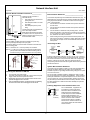
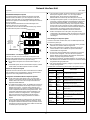
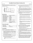
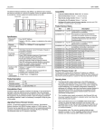
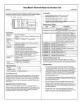
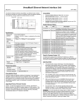
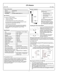
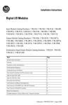
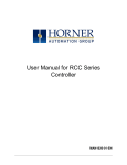
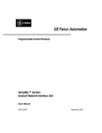
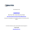
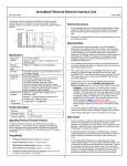
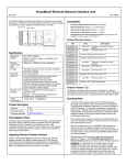
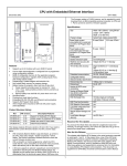
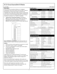
Network Interface Unit April 2000 GFK-1551C 4. Preinstallation Check _____________________________ Carefully inspect all shipping containers for damage. If any equipment is damaged, notify the delivery service immediately. Save the damaged shipping container for inspection by the delivery service. After unpacking the equipment, record all serial numbers. Save the shipping containers and packing material in case it is necessary to transport or ship any part of the system. Main Bus Connections Redundant Connections Quick Start Guide ________________________________ 1. Connect the communications bus to the NIU. (Refer to the heading Bus Installation Guidelines if the NIU is at the end of the bus, or for detailed bus installation instructions.) Install the NIU on the DIN Rail by simply clicking it into place. Note: The NIU and connecting carriers must be installed on the same section of 35mm x 7.5mm DIN rail. 5. The DIN rail must have a conductive (unpainted) finish for proper grounding. SERIAL A1 SERIAL A2 SHIELD IN SHIELD OUT SERIAL B1 SERIAL B2 SHIELD IN SHIELD OUT The NIU has two sets of bus terminals. The upper terminals are for the main bus cable. The lower bus terminals are for an optional redundant (dual) bus cable. Remove the connector cover on the righthand side of the NIU. Do not discard this cover; you will need to install it on the last carrier. It protects the connector pins from damage and ESD during handling and use. Do not remove the connector cover on the lefthand side. Connector Cover Connector Cover (Refer to the heading Module Installation for information about space requirements or module orientation, or if you are installing the NIU in an area of excessive vibration). 2. Install the Power Supply on the NIU. The latch on the power supply must be in the unlocked position. 6. Install additional modules by mounting modules on their carriers and sliding them along the DIN rail to fully engage the connectors in the sides of the carriers. 7. Power up the NIU. The modules in the I/O station will automatically be configured, starting at slot 1 in each rack including expansion racks. If an empty slot or faulted module is encountered, autoconfiguration for that rack stops. Autoconfiguration then skips to the next rack and continues until all racks are configured. Align the connectors and the latch post and press the power supply module down until the two tabs on the bottom of the power supply click into place. Turn the latch to the locked position to secure the power supply to the top of the NIU. Complete the power supply wiring as described in the installation instructions provided with the Power Supply. 3. Adjust the rotary switches on the front of the NIU using a 2.44mm (3/32in) flat screwdriver. (Refer to the NIU User’s Manual if the NIU is being configured using datagrams. U 0 1 2 3 A N SBA X10 Note: If the I/O station includes any additional power supplies, those power supplies must be turned on either before the NIU Power Supply or at the same time to assure accurate autoconfiguration. 9 0 1 8 7 SBA X1 2 3 BAUD RATE 6 5 4 0 1 N 2 3 8. Observe the NIU LEDs, which indicate the presence of power and show the operating mode and status of the NIU. PWR Indicates that the NIU is receiving power. OK Indicates diagnostics executed successfully. PWR Select the serial bus address with the two upper rotary switches, SBA X10 (for the tens digit) and SBA X1(for the ones digit). Each device on a bus must have a unique serial bus address in the range 0 - 31. OK FAULT I/O ENBL FORCE Select the baud rate to match that used by the other devices on the bus by setting the bottom rotary switch: (3) 153.6 Kbaud extended, (2) 153.6 Kbaud standard, (1) 76.8 Kbaud, or (0) 38.4 Kbaud. FAULT Is ON if there are one of more faults. I/O ENBL This bicolor LED is green if the I/O scan is enabled and data is being received from the bus. Otherwise, this LED is amber. FORCE Is ON if one of more I/O points is forced. SBA ERR Is ON if a duplicate device SBA or invalid SBA exists. BUS B Is ON if bus B is active. SBA ERR BUS B Cycle power to the NIU after changing the switch settings. 1 Network Interface Unit April 2000 GFK-1551C General Module Installation Instructions_____________ Bus Installation Guidelines ________________________ Modules must be mounted on a horizontal DIN rail. 1 133.35mm (5.25in) 2 85.85mm (3.38in) 3 1. Allow sufficient finger clearance for opening NIU door. 2. Allow adequate clearance for serial port cables. 3. Allow adequate space for power wiring. The maximum exposed length of unshielded wires should be 5cm (2in). For added protection, each shield drain wire should be insulated with spaghetti tubing to prevent the Shield In and Shield Out wires from touching each other, or the signal wires. 1. Connect Serial 1 to the Serial 1 terminals of the previous device and the next device. 2. The NIU with power supply attached fits into a 70mm deep enclosure. Connect Serial 2 to the Serial 2 terminals of the previous device and the next device. 3. Rated thermal specifications are based on a clearance of 5.1cm (2in) above and below the equipment and 2.54cm (1in) to the left of the NIU module. Connect Shield In to Shield Out of the preceding device. Connect Shield Out to Shield In of the next device. If the NIU is the first device on a bus, Shield In can be left unconnected. If it is the last device on a bus, Shield Out can be left unconnected. 4. When inserting two wires into the same terminal block position, the wire size must be 0.86mm2 (18AWG) or smaller. Both wires should be of the same size and style. Do not mix stranded with solid wire in the same position. Panel-Mounting For best stability, the DIN rail should be installed on a panel using screws spaced approximately 5.24cm (6in) apart. Terminating the Bus If excessive vibration is a factor the NIU should also be screwed down to the mounting panel. Start of Bus Terminating Resistor Note 1. Tolerances are +/- 0.13mm (0.005in) non-cumulative. Note 2. 1.1-1.4Nm (10-12 in/lbs) of torque should be applied to M3.5 (#6-32) steel screw threaded into material containing internal threads and having a minimum thickness of 2.4mm (0.093in). End of Bus Serial 1 Serial 2 Shield In Shield Out Terminating Resistor Serial 1 Serial 2 Shield In Shield Out SEE NOTE 2. 4.3mm 0.170in M3.5 (#6) SCREW If either bus will terminate at the NIU, connect a 75, 100, 120, or 150-ohm terminating resistor across the Serial 1 and Serial 2 terminals. The use of a ferrule is recommended to crimp each resistor lead to the corresponding serial line. If ferrules are not used, twist each resister lead with the corresponding serial line and solder them together before inserting the wires into the terminal block. SPLIT LOCK W ASHER FLAT W ASHER 4.3mm 0.170in 15.9mm 0.62in REF 5.1mm 0.200in System Bus Installation Guidelines TAPPED HOLE IN PANEL The serial bus can be treated as a Class 2 circuit when appropriate wiring practices are followed. Maximum bus lengths may be affected when installation requires the high-voltage rated CM rating. CM types can replace CL2, but not vice versa. NIU Removing the NIU from the DIN Rail 1. 2. 3. 4. Turn off power to the power supply. (If the NIU is attached to the panel with a screw) remove the power supply module. Remove the panel-mount screw. Slide the NIU away from the other modules until the connector on the right side disengages from the next carrier. With a small flathead screwdriver, pull the DIN rail latch out while tilting the other end of the NIU down to disengage it from the DIN rail. Do not mix cables of different impedance, regardless of cable run length. Do not mix cable types in long and/or noisy installations. Other, small-size twisted pair shielded wire of unspecified impedance can be used for short runs of 50 feet or less, using 75 ohm terminations. Selection of wire type may be limited by local and national codes and industry standards. Consult the cable manufacturer to determine the cable's suitability for a particular type of installation. Installing Suppression at the Communications Line SHLD OUT SHLD IN S2 S1 MOVs 2 (bus cable not shown) For an individual NIU, suppression can be supplied by connecting two small MOVs from Serial 1 and Serial 2 to the Shield Out terminal. Suitable MOVs include Harris part number V220MA2A, Panasonic ERZ-CO5FK221U, and Siemens 505K140. Higher energy-rated devices can also be used. Follow the wiring instructions above for installing MOVs. Be sure the MOV leads do not cause shorts between the serial data and shield connectors. Network Interface Unit April 2000 GFK-1551C Product Description ______________________________ Revision Letters: AC Firmware version: 1.50 Firmware upgrades: 44A748000-G02 Compatibility _____________________________________ Any type of PLC or computer capable of controlling the bus can be used as the host. This Network Interface Unit is compatible with: - Specifications ___________________________________ Number of Modules 8 per NIU/station Network inputs per bus scan 128 bytes Network outputs per bus scan 128 bytes Discrete Input Memory 1024 points Discrete Output Memory 1024 points Analog Input Memory 128 bytes Analog Output Memory 128 bytes Power Consumption +5V@250mA, +3.3V@10mA Serial Bus Address 0 to 31 Network data rate 153.6 Kbaud extended, 153.6 Kbaud standard, 76.8 Kbaud, or 38.4 Kbaud. CPU firmware, release 3.0 or later. Bus Controller release 5.4 or later If the IC641SWP701/704 programming and configuration software is used, it must be release 3.0 or later. For an IC693 PLC - CPU firmware: any version for NIU compatibility. If the NIU I/O station includes any expansion racks, the CPU must be a model 350, 352, 360, 363, or 364, Release 10.0 or later. If an earlier version of CPU firmware is used or if any other Series 90-30 CPU model is used, a Loss/Add of Rack fault causes the CPU to go to Stop/Faulted mode. Bus Controller: any version. For an IC600PLC: - New Feature of this NIU Version ____________________ For an IC697 PLC Supports the use of expansion transmitter/receiver modules. This capability allows up to seven additional I/O racks to be cascaded off a single NIU. It is important to note that the total amount of I/O data that can be exchanged by the NIU is 128 bytes of discrete + analog inputs and 128 bytes of discrete + analog outputs. Additional I/O are ignored. CPU: rev. 105 or later Programming Software: Release 4.02 or later - Bus Controllers: CBB902 or 903, version 1.7 or later To be used in an expansion rack, analog modules IC200ALG320, 321, 322, and 432 must be revision B or later. Analog modules IC200ALG430 and 431 that are used in expansion racks must be revision C or later. Expansion Systems _______________________________ This section summarizes the expansion capabilities of this NIU version. For more information about expansion modules, installation and required equipment, please refer to current version of the I/O Modules, Power Supplies, and Carriers Manual, and to the documentation supplied with Expansion Transmitter and Receiver Modules. Operating Note/Restrictions for this NIU Version _____ If the NIU is configured via datagrams from the bus, the value of the Force BSM bit is accessible but must not be changed. Regardless of the number of racks used, the maximum I/O capacity of the NIU system is 128 bytes of discrete +analog inputs and 128 bytes of discrete + analog outputs. Any additional I/O is ignored. No analog modules or intelligent I/O modules should be used in a Duplex Redundancy system. Two-Rack Local System During a firmware upgrade to an intelligent I/O module, outputs hold last state regardless of their configuration. The NIU does not detect a configuration mismatch for jumper configurations on the ALG260 and 230 modules and the ALG262 and 264 modules. For these module pairs, the NIU does not detect the difference between bi-polar voltage and 4-20mA current configuration. For the ALG262 and 264 modules, the NIU does not detect the difference between uni-polar voltage and 0-20mA current configuration. This type of system uses one Non-Isolated Expansion Receiver *ERM002 to connect just one expansion rack to the NIU I/O Station without having an Expansion Transmitter Module in the main rack. This “single-ended” configuration has a maximum cable length of 1 meter. No terminator plug is required in the expansion rack. NIU I/O Station Main Rack PS Fixed for this Version _____________________________ Cable *CBL600 (1M) If the NIU is powered up with autoconfiguration enabled via the NIU rotary switches, and the NIU was previously configured for Hot Standby CPU Redundancy, the I/O Enabled LED lights green even if there is an address error. (Module MDL730 only) After a short circuit condition on discrete output module MDL730, it may be necessary to issue two Clear All Faults commands to clear both the Fault LED and the diagnostic fault message. If the I/O station includes any intelligent module powered by a booster power supply and power is cycled quickly and repeatedly on the booster power supply but not the NIU power supply, the NIU may record a configuration mismatch fault for the intelligent module. NIU Expansion Rack PS ERM 3 Network Interface Unit April 2000 GFK-1551C RS-485 Differential Expansion System A multi-rack expansion system requires an Expansion Transmitter Module in the NIU I/O Station. Up to seven expansion racks can be included in the system. With any non-isolated Expansion Receiver Module in the system, the total overall length of the expansion cable can be up to 15 meters. With all Isolated Receiver Modules, the total overall length of the expansion cable can be up to 750 meters. The expansion bus must be terminated with terminator plug *ACC201 (included with the Expansion Transmitter). In an local system, the NIU rack and the expansion rack may be on different power supplies if desired. If so, on a single-ended or differential system, disconnecting the cable between the NIU/transmitter and receivers may cause disruptions on the bus. In a multiple-rack expansion system, if a new expansion rack is added in the future, it should be assigned a rack address that is higher than the racks that are already installed. If a new expansion rack with a lower rack number than those previously auto-configured is installed and the system is auto-configured, the racks numbered higher than the new rack number have their I/O reference addresses shifted in the reference tables. Any existing program logic that uses those references must then be adjusted to use the new references. To add a new expansion rack to the system, the system must be powered down. After adding the module, according to the instructions in the Expansion Module datasheet, power up the system. It will then autoconfigure. I/O Station Main Rack (0) ETM PS NIU ExpansionRack 1 Fault Handling for an Expansion System PS 15M with any ERM002 Modules This version of the NIU can detect extra, lost, and added expansion racks as a result of a power cycle. 750M with all ERM001 Modules ERM ICBL601, 602, 615 ExpansionRack 7 PS Terminator Plug ERM When a complete rack is lost, only a “Loss of Rack” fault is generated. Individual “Loss of Module” faults are suppressed. When a rack is added only an “Addition of Rack” fault and any I/O module mismatch or loss conditions are reported. Individual I/O module additions are suppressed. An “Extra rack” fault is generated when an expansion rack is present but has not been configured. The Scan LED on the Expansion Receiver Module is green instead of yellow whenever the Expansion Receiver is properly configured and is working. Hot swapping of Expansion Transmitter Modules is not supported. The NIU detects the loss and addition of the Expansion Transmitter Module and generates the appropriate faults. If the run-time expansion frequency changes, an “Expansion bus speed change” fault is generated. Communications in an Expansion System The NIU in the main rack communicates with the expansion racks through a high-speed serial interface. The frequency used depends on the types of expansion receivers in the expansion rack(s). In a Two-Rack Local system, the communications frequency is 3MHz. In Differential system, the NIU communications frequency is 3MHz unless at least one isolated expansion receiver is installed. The table below summarizes programmer faults in an expansion system: Modules for an Expansion System Programmer Fault Text VP/C90 LM90 Fault Description Expansion racks are built from the same carrier bases and I/O modules that are allowed in main rack applications. Note the special revisions required for some analog modules mentioned above. Expansion Bus Speed Change Reset of, Addition Expansion bus operating frequency has changed of, or extra option from 250kHz to 3MHz or vice versa. module Configuration and Installation Notes for Expansion Systems Addition of rack Addition of, or extra rack Occurs when a receiver is first configured and when it returns after being lost. Loss of, or missing rack Loss of, or missing rack Occurs when a properly configured receiver is not physically present at power up or lost at run-time. System Configuration Mismatch System Configuration Mismatch The configuration stored for a receiver does not match the physical receiver present. Extra Rack Addition of, or extra rack Loss of, or missing option module Loss of, or missing option module Generated when a properly configured transmitter module in a differential rack system is not present. Reset of module Reset of, Addition of, or extra option module Generated when a transmitter in a differential rack system is either configured for the first time or is now present after being lost. Extra module present but not configured Reset of, Addition of, or extra option module Generated when a system is configured for singleended operation and a transmitter module is present. The NIU must have its rack dial set to rack 1 or it will not autoconfigure. The Expansion Receiver modules also have Rack ID selection dials. Each must be set correctly as described in the Expansion Module datasheets. In a multiple-rack expansion system, any available rack number can be used for a new expansion rack but they must all be unique (no duplicate rack numbers). It is best to assign expansion racks numbers from lowest (1) to highest (7) as they are installed. That is most compatible with the NIU auto-configuration feature. Autoconfiguration automatically assigns reference addresses to I/O points and channels as it configures them. Autoconfiguration starts in the main rack and proceeds through the slots and additional racks in order, assigning references from lowest to highest. To force auto configuration for expansion racks, first power down the NIU. Remove the transmitter module from the NIU or remove the expansion cable at the transmitter. Power up the NIU and let it autoconfigure. Power the NIU down again, reattach the transmitter or cable and power up the NIU again. Extra Transmitter 4 Generated when a receiver is present that is not currently configured. Also indicates improperlynumbered rack ID. Expansion Transmitter installed in 2-rack local system