1
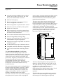
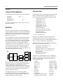
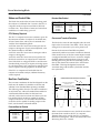
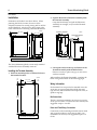
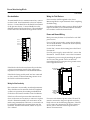
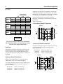
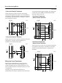
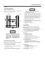
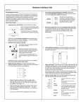
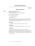
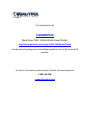
This Datasheet for the
IC660BPM100
Block Power TRAC 115Vac/125Vdc Power Monitor
http://www.qualitrol.com/shop/p-14447-ic660bpm100.aspx
Provides the wiring diagrams and installation guidelines for this GE Series 90-30
module.
For further information, please contact Qualitrol Technical Support at
1-800-784-9385
[email protected]
Power Monitoring Block
IC66*BPM100
August 1995
H
H
H
H
H
H
H
H
H
H
H
H
H
H
Accurately measures the RMS values of voltage,
current, power, VARs, power factor, and watthours, even with distorted waveforms.
Measures line frequency.
Detects and captures overcurrent waveforms
above a configurable current level.
Indicates magnitude of system harmonic content.
For both wye (4-wire) and delta (3-wire) systems.
Simple user connections.
Direct connection for up to three potential transformers and three line current transformers plus
one neutral current transformer.
Low current transformer burden (less than 0.1VA).
Software configurable, including scaling.
Small size and rugged design for mounting in electrical distribution and process equipment.
Integral power supply accepts either 115/230 VAC
or 125 VDC inputs.
Can be installed on bus up to 7500 feet from host.
Compatible with CPU redundancy configurations.
Can be used for stand-alone monitoring without a
host.
The Power Monitoring Block (IC66*BPM100)
monitors current and voltage inputs and stores
digitized waveform values for each input. From these
values, the block calculates RMS values of voltage,
current, active power, reactive power, KWH, and
power factor. Frequency is also measured. The block
automatically sends this calculated data to a
programmable controller or host computer
approximately twice per second. The same data can
be displayed on a Hand-held Monitor from any
location on the bus.
If an overcurrent transient exceeds a configurable level,
the block captures the resulting waveform. A simple
measure of system harmonic content indicates the
extent to which this problem exists. The block will
supply waveform data to the PLC or computer, for
harmonic or transient analysis, upon request.
The block can be used with a wye or delta configured
three-phase power system or with a single-phase
GFK-0366E
power system. It accepts voltage inputs from as many
as three potential transformers, and current inputs
from one to three line current transformers, plus a
neutral current transformer.
The turns ratios of both current transformers and
potential transformers are software-configurable.
Current transformers with a secondary rating of up to
5 amps and primary ratings up to 3275 amps for line
connections or 325 amps for auxiliary (neutral)
connections may be used. Potential transformers with
a secondary rating up to 120VAC (47–63 Hz) and
primary ratings up to 327KV may be used, with
line-to-line or line-to neutral connections.
ÎÎ
Î
ÎÎÎ
Î
ÎÎÎÎÎÎ
Î
Î
ÎÎ
ÎÎ
ÎÎ
ÎÎ
ÎÎ
ÎÎ
ÎÎ
ÎÎ
ÎÎ
ÎÎ
ÎÎ
Î
ÎÎÎ
a43592
The Power Monitoring Block can be powered from
either 115/230 VAC (90–265 VAC) 47–63 Hz, or 125
VDC (100–150 VDC) at 1 amp, maximum. It can be
installed on electrical distribution or process
equipment, in a junction box, or rack or
panel-mounted up to 7500 feet from the host. Use of
a Hand-held Monitor also allows stand-alone
operation.
The block’s Electronics Assembly may be inserted or
removed without disturbing block configuration or
field wiring (no CT shorting clips are required).
2
Power Monitoring Block
GFK-0366E
Content of this Datasheet
Calculated Data
This datasheet describes the features and installation
Approximately twice a second, the Power Monitoring
Block calculates the following RMS values, based
upon the current content of the Working Data Table.
Operation
Installation
Configuration
Specifications
page
2
4
8
10
For additional information, see the Power Monitoring
Block User’s Manual.
Operation
The Power Monitoring Block uses both analog and
digital techniques to provide accurate and stable RMS
measurements, even in the presence of higher-order
harmonics. These measurements are fully updated
about twice a second.
To accomplish this, the block samples all current and
voltage inputs at an equivalent rate of 128 samples
per cycle. Samples are taken at the rate of 16 samples
per cycle for 8 consecutive cycles. These composite
waveforms are stored in a Working Data Table for
computation of the new measurements. The stored
waveforms may also be used for harmonic analysis;
they can be read by the PLC or remote computer
using Read Device datagrams. This is described in the
Power Monitoring Block User’s Manual.
CURRENT
AND
VOLTAGE
INPUTS
Ia
Ib
a43593
STATUS
DATA
SIGNAL
CONDITIONING
Ic
Ix
Va
Vb
Vc
MULTIPLEXER
B
ANALOG
TO
DIGITAL
CONVERTER
WORKING
DATA
CALCULA TED
DATA
U
S
OVERCURRENT
DATA
XMIT
DATA
BUFFER
Both voltage and current inputs are processed to
maximize accuracy over the specified measurement
range, while still providing the ability to track
overload conditions at a reduced accuracy. Sampling
is referenced to line frequency using phase-lock loop
circuitry. All inputs are sampled simultaneously to
maintain phase correlation.
The digitized inputs are also stored in another
internal table called the Overcurrent Data Table in
order to support overcurrent transient capture. This
feature is described on the next page.
voltage, phase A to B
voltage, phase B to C
voltage, phase C to A
voltage, phase A to N*
voltage, phase B to N*
voltage, phase C to N*
current: phase A, B, and C
current, auxiliary CT
active power: phase A, B, and C
reactive power: phase A, B, and C
total power factor
totalWH/KWH/MWH
* for line-to-neutral PTs only
Each bus scan, the block sends these 36 bytes of
calculated data to the PLC or host computer. This
data can also be displayed on a Hand-held Monitor in
either a system or stand-alone configuration.
In addition to the above data, the Power Monitoring
Block calculates the following values:
fundamental VARs: phase A, B, C
fundamental Power Factor
harmonic VARs as % of V-A: phase A, B, C
harmonic VARs as % of total system V-A
line Frequency
temperature alarm status
extended watt-hours
All values are reported as 16-bit two’s complement
numbers. Active Power, Reactive Power, and Power
Factor are signed values. Calculated data has the
following valid ranges:
voltage:
line current:
aux. current:
power:
power factor:
VARs:
fund PF:
har. VARs
line freq.:
temp. alarm:
extended watt-hours (high):
extended watt-hours (low):
0 to 327 KVolts
0 to 3276.7 Amps
0 to 327.67 Amps
–32768 to +32767
–1.000 to +1.000
–32768 to +32767
–1.000 to +1.000
0 to 100
47.0 to 63.0
–1, 0, +1
0 to 32767
0 to 999
Power Monitoring Block
3
GFK-0366E
Extended Data Enabled
Status and Control Data
The block also sends 16 bits of status data along with
the 36 bytes of calculated data. In return, the PLC or
computer sends 16 output control bits to the block
each bus scan. This transfer of status and control bits
establishes a “handshaking” protocol.
Baud Rate
153.6 Kb. st
153.6 Kb. ext
76.8 Kb
38.4 Kb.
A
5.02
5.10
10.18
20.384
B
5.38
5.46
10.90
21.814
CPU Memory Required
The PLC or computer must reserve memory space for
the automatic transfer of 36 bytes of calculated data,
16 bits of status data, and 16 bits of command data
with the Power Monitoring Block.
An IC600- series PLC must reserve 24 inputs and 16
outputs or 20 registers. Inputs are multiplexed, with
the channel number in the MSB.
An IC655- series PLC must reserve 304 inputs and 16
outputs or 20 registers.
An IC697- series PLC must reserve 16 input bits for
the block’s status data, 16 output bits for command
data. If the block is configured NOT to send the extra
data described previously, it requires 18 analog inputs
for calculated data. If it is configured to send the extra
data, it requires 30 analog inputs for calculated data.
If the PLC or computer will read table data for
transient or harmonic analysis, additional memory
will be required.
Overcurrent Transient Detection
The block also stores the 128 sampled values for each
input in the Overcurrent Data Table. There, they are
arranged as 8 consecutive cycles of 16 points each.
Data in the Overcurrent Data Table is updated
continuously until an overcurrent transient is detected.
If the current on any of the four current inputs exceeds
a configured transient level for two successive samples,
the block captures and stores three cycles up to and
including the event, plus the five succeeding cycles of
data. It then freezes the contents of the Overcurrent
Data Table. This traps the digitized overcurrent
waveform along with the three cycles before and the
five cycles after it.
a43594
I (A)
35
Bus Scan Contribution
CURRENT TRANSIENT ABOVE CONFIGURED LEVEL FOR TWO
SUCCESSIVE SAMPLES. NEXT 5 CYCLES WILL BE SAMPLED.
30
The scan time contribution for the block depends on the
baud rate, the number of controllers on the bus and
whether or not Extended Data reporting is enabled.
The following tables show the scan time contribution
at each baud rate, without Extended Data enabled or
with Extended Data enabled. At the baud rate
selected, use the time in column A if there is just one
bus interface block on the bus capable of sending
outputs to the block. If a second bus interface block
on the bus is also capable of sending outputs to the
block, use the time in column B instead.
25
20
CONFIGURED OVERCURRENT
TRANSIENT LEVEL
THESE TWO CYCLES OCCURRED
BEFORE THE OVERCURRENT TRANSIENT
CYCLE 2
CYCLE 3
CYCLE 4
15
10
5
Extended Data Not Enabled
Baud Rate
153.6 Kb. st
153.6 Kb. ext
76.8 Kb
38.4 Kb.
A
B
3.30
3.38
6.76
13.52
3.66
3.74
7.48
14.95
When a current transient occurs, the block sets a bit in
the status data it sends to the PLC or computer.
Transient data can be read by the PLC or computer
Read Device datagrams. This is described in the Power
Monitoring Block User’s Manual
4
Power Monitoring Block
GFK-0366E
Installation
Dimensions of the block are shown below. When
planning the block’s location, be sure to allow
adequate clearance for routing wiring and for airflow
around the block. Also be sure to leave room at the
front of the block for attaching a Hand-held Monitor.
Î
ÎÎ
ÎÎÎÎ
ÎÎÎÎ
a43595
8.06 (20.47)
.18 (.46)
5.21 (13.23)
2. Separate the block’s Electronics Assembly from
the Terminal Assembly.
Grasp the block firmly, and pull the Electronics
Assembly out straight, away from the Terminal
Assembly.
ÎÎ
ÎÎ
TERMINAL ASSEMBLY
a43597
11.00
(27.94)
ÎÎÎÎ
ÎÎ
CONNECTORS
DIMENSIONS IN INCHES, CENTIMETERS IN PARENTHESIS
The Power Monitoring Block is most easily installed
with the Electronics Assembly removed
Installing the Terminal Assembly
1. Drill four mounting holes as indicated below at
the intended location.
.22
(.56)
a43596
5.21 (13.23)
3.25 (8.26)
.43
(1.09)
ÎÎ
Î
ÎÎÎÎÎ
Î
RETAINING SCREWS
(QTY 2)
ELECTRONICS ASSEMBLY
ÎÎÎÎÎ
ÎÎ
Î
3. Line up the notches in the top and bottom of the
Terminal Assembly with the drilled holes.
Fasten it securely in place using up to #12 screws
with star washers.
After installing the Terminal Assembly, complete the
block wiring as described on the following pages.
Wiring Information
Each terminal can accept solid or stranded wires; the
wires into any given terminal should be the same
type and size. The terminals will accept bare wires, or
spade or ring lugs.
10.56
(26.82)
11.00
(27.94)
Bus Connections
The bus connection terminals can accept two copper
wires up to size AWG #14 (2.1mm2 cross section). The
suggested torque is 9 in–lbs.
Power and Field Wiring Connections
DIMENSIONS IN INCHES,
CENTIMETERS IN PARENTHESIS
Connections to the remaining terminals can be made
with copped conductors, wire sizes up AWG #10
(5.02mm2 cross section). The suggested torque is 12
in–lbs.
Power Monitoring Block
5
GFK-0366E
Bus Installation
Wiring for Field Devices
To install the block on a communications bus, connect
its Serial 1 and Serial 2 terminals to those of adjacent
devices. Connect Shield In to the Shield Out terminal
of the previous device. Connect Shield Out to the
Shield In terminal of the next device. The unshielded
ends of the wires should not be longer than 2 inches.
SERIAL 1
SERIAL 2
SHIELD IN
SHIELD OUT
Î
Î
Î
Î
Power must be NOT be applied to the Power
Monitoring Block or input terminals when completing
the field wiring.
If conduit will be used to bring wires or cables for field
inputs to the block, its size and installation should be
in accordance with local electrical code.
Power and Ground Wiring
a43598
Block power may be from a 115/230 VAC or 125 VDC
power source.
For a 115 VAC power supply, connect the hot (black)
wire to the H terminal. Connect the neutral (white)
wire to the N terminal.
For 230 VAC, connect the incoming line to the H and
N terminals.
For a DC power supply, connect the DC+ wire to the
H terminal. Connect the DC- wire to the N terminal.
Complete the power wiring by attaching the ground
wire to one of the ground screws on the block.
Ground the block by wiring one of its ground screws
to the equipment chassis.
If the block is the last device (electrically) on the bus,
connect a terminating resistor of the appropriate
impedance across the Serial 1 and Serial 2 terminals.
GROUNDING
SCREW
If the block is being used by itself, and not connected
to a bus, install a 75-ohm terminating resistor across
the Serial 1 and Serial 2 terminals.
ÎÎÎÎÎ
Î
ÎÎÎÎÎÎ
a43599
Wiring for Bus Continuity
Bus connections are normally considered permanent.
They should never be removed while the completed
system is in operation; the resulting unreliable data
on the bus could cause hazardous control conditions.
If the bus will control processes that cannot be shut
down in the event it is necessary to remove or replace
a block’s Terminal Assembly, bus connections can be
made using intermediate connectors, or wire ends can
be soldered together before inserting them into the
terminals. For more information, see the I/O System
User’s Manual.
ALTERNATE
GROUND
CONNECTION
POINT
ÎÎÎÎÎ
ÎÎÎÎÎ
For correct calculation of power values, PTs and CTs
must be connected to the power phases and to the
block as shown in the following diagrams. If the PTs
or CTs cannot be connected to the power phases as
shown, refer to the Power Monitoring Block User’s
Manual for instructions.
6
Power Monitoring Block
GFK-0366E
Number
of PTs
(L–N)
Number
of PTs
(L –L)
three
Current/Voltage
Input Terminals
A/R
B/S
C/T
A–N
B–A
C–N
two
A–N
C–N
B–N
one
three
B–C
two
B–C
C–A
If there are just two line-to-neutral PTs, one must be
connected from phase A to neutral and to the block’s
R terminals. The other must be connected from phase
C to neutral, and to the block’s T terminals.
If there is just one line-to-neutral PT, it must be
connected from phase B to neutral and to the block’s
S terminals.
Short unused inputs.
A–B
3 Line-to-Neutral Potential Transformers
A–B
a43600
(LINE SIDE)
C–A
one
N
A
B
C
R+
Number
of CTs
three
phase A
two
phase A
phase B
phase C
phase C
R
POWER
S+
phase B
one
VOLTAGE
S
T+
Warning
T
(LOAD SIDE)
For personal safety, PT AND CT SECONDARIES
MUST BE GROUNDED. Recommended grounding
is shown in the diagrams that follow.
Power Flow
Transformers should be connected to the block with
the dots as shown in the wiring diagrams. If this is
done, power flow in the direction indicated by the
arrow in each illustration will provide a + reading for
that input.
3 Line-to-Line Potential Transformers
For proper calculation of power values, the block’s R,
S, and T terminals must be connected to these
line-to-neutral PTs:
R terminals:
S terminals:
T terminals:
Phase B to phase C PT
Phase C to phase A PT
Phase A to phase B PT
B
C
Wiring from Potential Transformers
R+
Refer to the examples below to connect potential
transformers to the Power Monitoring Block.
R
POWER
S+
For proper calculation of power values, the block’s R,
S, and T terminals must be connected to these
line-to-neutral PTs:
R terminals:
S terminals:
T terminals:
Phase A to neutral PT
Phase B to neutral PT
Phase C to neutral PT
a43601
(LINE SIDE)
A
VOLTAGE
S
T+
T
(LOAD SIDE)
Power Monitoring Block
7
GFK-0366E
2 Line-to-Line Potential Transformers
If there are just two line-to-line PTs, one must be
connected from phase B to phase C and to the block’s
R terminals. The other must be connected from phase
A to phase B, and to the block’s T terminals. Connect
the S terminals as shown.
B
3 Line Current Transformers
1 Neutral Current Transformer
a43602
(LINE SIDE)
A
current transformer input terminals. No spring-type
contacts are used. Burden is maintained with the
electronics block removed.
POWER
a43604
(LINE SIDE)
C
N
A
B
C
R+
A+
R
A
S+
POWER
B+
VOLTAGE
S
B
T+
C+
T
C
CURRENT
(LOAD SIDE)
X+
1 Line-to-Line Potential Transformer
X
If there is just one line-to-line PT, it must be connected
from phase C to phase A and to the block’s S
terminals. Short the unused inputs.
a43603
(LINE SIDE)
A
B
C
2 Line Current Transformers
1 Neutral Current Transformer
If there are just two line CTs, one must be connected
from phase A to the block’s A terminals. The other
must be connected from phase C to the block’s C
terminals.
R+
R
POWER
(LOAD SIDE)
S+
VOLTAGE
N
A
B
C
A+
T+
A
T
(LOAD SIDE)
a43605
(LINE SIDE)
S
POWER
B+
Wiring from Current Transformers
B
Refer to the examples below to connect current
transformers to the Power Monitoring Block. For
proper calculation of power values, the block’s A, B,
and C terminals must be connected to phase A, B, and
C respectively.
C+
For safety, current transformer burdens are
permanently and directly connected across the block’s
CURRENT
C
X+
X
(LOAD SIDE)
8
Power Monitoring Block
GFK-0366E
1 Line Current Transformer
1 Neutral Current Transformer
Caution
If there is just one line CT, it must be connected from
phase B to the block’s B terminals.
a43606
(LINE SIDE)
N
A
B
C
A+
A
POWER
B+
B
CURRENT
C+
Do not exert excessive force. Damage to
the equipment can result.
If unusual resistance is met, remove the Electronics
Assembly. Check the keying and inspect the Terminal Assembly, connector receptacle, and connector edge board on the Electronics Assembly. If necessary, remove any obstacles and reinsert the
Electronics Assembly. Pay close attention to the
alignment of the guide pins.
3. Secure the Electronics Assembly with the screws
on the top and bottom.
4. Apply power to the block.
C
X+
Compatibility
X
The Power Monitoring Block is compatible with:
(LOAD SIDE)
Warning
NEVER disconnect any current transformer wiring from the Power Monitoring Block when current is flowing in the
primary circuit. The resulting hazardous
voltages MAY CAUSE INJURY OR
DEATH.
Install the Electronics Assembly
The Electronics Assembly and Terminal Assembly are
keyed to assure a correct installation.
1. Align the Electronics Assembly
Use the shoulder screws on the side of the Terminal Assembly as a guide.
2. Push the Electronics Assembly down quickly.
Hand-held Monitor: version 3.5 or later provides
basic compatibility with a Power Monitoring Block. If
the block is assigned to register references, HHM
version 3.8 is required to display the additional
calculated data listed on page 2.
PLC CPUs:
IC697CPU731G or later
IC697CPU771E or later
IC697CPUxxx: all versions
IC600 series PLC CPU: rev. 105 or later
IC600 PLUS series PLC CPU: rev. 110 or later
IC655 series PLC CPU rev. 4.0 or later
Programming Software
(IC641SWP701/702) rel. 2.02 or later
IC641PBE series software, release 4.02 or later
IC641PFE500 or PTE series software, release 2.01
or later
Bus Controllers:
IC697BEM731C or later
IC66*CBB902 or 903, version 1.7 or later.
IC655BEM500, any version
PCIM or QBIM: any version
Power Monitoring Block
9
GFK-0366E
The Power Monitoring Block must be configured with
a Hand-held Monitor to:
Power Display Units: Selects whether power
measurements will be reported to the CPU as Watts,
Megawatts, or Kilowatts. This entry is also used to
scale VARs, power, and energy.
H
H
PT Turns Ratio: Specifies the turns ratio of the PT(s).
Range is up to 327600.0:120 (2730.0:1) maximum.
Power Monitoring Block Configuration
Enter its Block Number (serial bus device number).
Enter its Reference Number (not required for
PCIM or QBIM). The Power Monitoring Block
requires 304 I/O references.
Additional features of the block, described below, can
be changed by configuration from the Hand-held
Monitor or the application program. Selections and
the default configuration of each feature are shown in
the table at the bottom of the page.
Baud Rate: May be 153.6 Kbaud standard, 153.6
Kbaud extended, 76.8 Kbaud, or 38.4 Kbaud. All
devices on the bus must use the same baud rate.
CPU Redundancy: Selects no redundancy or “Hot
Standby” mode.
Configuration Protection: Prevents accidental or
unauthorized changes to the block’s configuration.
PT Connection: Specifies whether the potential
transformer connections are line-to-neutral or
line-to-line.
CT Turns Ratio: Specifies the turns ratio of the CT(s).
Range is up to 3275:5 (6550:1) maximum.
NCT Turns Ratio: Specifies the turns ratio of an NCT.
Range is up to 325:5 (655:1) maximum.
Overcurrent Transient: A value in peak Amps which
represents the maximum allowable current on the
current transformers. If a current transient above this
level occurs, the block will continue to store the
waveform for the next five cycles, and inform the
CPU that a transient has occurred. The CPU can then
request the transient data from the block.
Auxiliary Overcurrent Transient: A value in peak
Amps which represents the maximum allowable
current on a neutral current transformer. This is
handled as described above.
Number of PTs: Specifies the number of potential
transformers connected to the block (1 to 3).
Sign Convention for VARs and Power Factor: Selects
the sign convention used by the block.
Number of CTs: Specifies the number of line current
transformers connected to the block (1 to 3). Does not
include the neutral current transformer.
Send Extra Calculated Data: Can be used to enable
automatic sending of the block’s additional calculated
data (see page 2).
Default Configuration
Feature
PT Connection
Number of PTs
Number of CTs
Power Display Units
PT Turns Ratio
CT Turns Ratio
NCT Turns Ratio
Current Line Transient
Auxiliary Current Transient
Sign for VARs and Power Factor
Send Extended Calculated Data
Baud Rate
BSM Present
CPU Redundancy
Config. Protect
Selections
line to line, line to neutral
1–3
1–3
Watts, MegaWatts, KiloWatts
1.0 to 2730.0
1 to 6550
1 to 655
up to 4500A
up to 450A
Mode A or Mode B
no, yes
153.6 st, 153.6 ex, 76.8, 38.4 Kbaud
yes/no
none, hot standby
enabled/disabled
Default
L–N
3
2
KWatts
60.0
200
5
3276
327
Mode A
no
153.6 st
no
none
disabled
10
Power Monitoring Block
GFK-0366E
Power Monitoring Block: Specifications
Voltage Inputs:
Maximum
NominalRange
Overvoltagerange
Transientrange
Burden per input
Accuracy of measured voltages
Configurable PT turns ratios
Current Inputs:
Nominalrange
Transientrange
Overcurrentwithstand
Burden per input
Accuracy of measured current
Configurable CT turn ratios
Frequency Accuracy:
PowerMeasurement Accuracy:
Power Supply Requirements:
Terminal Wiring:
LEDs:
Functionality:
Voltage
Current
Active Power
Reactive Power
Power Factor
KWH
UpdateRate
Frequency
Block Ambient Temp. Status
Harmonics
Environmental:
OperatingTemperature
Storage Temperature
Humidity
Vibration
Dimensions
H
H
one to three phases (delta or wye)
60 to 120 VAC RMS at 47 to 63 Hz
up to 300V peak
up to 300V peak
less than 0.1 VA
$ 0.25% reading + 0.25% full scale for nominal range
1.0:1 to 2730:1, up to 327KV
one to three phases
0 to 5 Amps RMS at 47 to 63 Hz
5 to 50 Amps RMS at 47 to 63 Hz
50 amps for 5 seconds, at 10–minute intervals
less than 0.1 VA
$ 0.50% reading + 0.50% full scale
655 : 1 (up to 3200 amps)
$ 0.1Hz
$ 0.75% reading + 0.75% full scale (PF 0.8 or greater)
115 VAC/230V
AC (90–265VAC),
47–63 Hz or 125 VDC (100–150VDC) at 35VA max.
for I/O bus: one AWG #12 or two AWG #14) for power, CTs,
and PTs: up to AWG #10
Unit OK, Communications OK
Per phase
Per phase and neutral
Per phase
Reactive Power
Effective system PF
Total system
2/second
system
low, normal, high
total harmonicpowercontent/phase
0°C to +60°C (+32°F to +140°F)
–40 °C to +100°C (–40°F to +212°F)
5% to 95% non-condensing
1.0 G 10–200Hz
5.21” w. X 11.00” h. X 8.06” d.
13.23cm w. X 27.94cm h. X 20.47cm d.
Electronics removable from terminal strip while maintaining electrical continuity on CT secondaries.
Designed in accordance with UL and CSA, ANSI C37.90, NEMA 2-230, IEEE 587