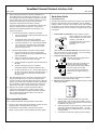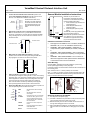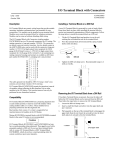
1
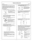
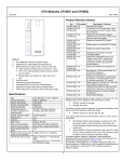
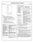
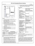
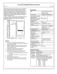
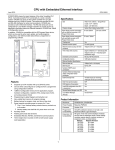
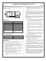
VersaMax® Genius® Network Interface Unit
May 8, 2009
GFK-1551Q
The Genius Network Interface Unit acts as controller for a set of I/O
modules. Power for module operation is provided by a power supply that
installs directly on the NIU
NIU
If any of the following are used, either a Loss of rack or Addition of
rack fault will cause the CPU to go to Stop/Fault mode:
-
CPU350, 352, 360, 363, or 364 with firmware version 9.11 or
lower; or
-
CPU311, 313, 321, 323, 331, 340, 341, or 351 (all versions).
power supply
4.
VersaMax analog I/O modules IC200ALG320, 321, 322, and 432
that are used on Genius NIU expansion racks must be revision B or
greater. VersaMax analog I/O modules IC200ALG430 and 431 that
are used in Genius NIU expansion racks must be revision C or
greater.
5.
When a Genius NIU (version –GJ or later) is used in a control loop
that is seeking SIL2 or SIL3 status, Proficy Machine Edition version
5.60 plus SIM 8 (or later) is required to configure Enhanced
Diagnostics mode.
Specifications
Number of modules
8 per rack, up to eight racks.
Network inputs per bus scan
128 bytes
Network outputs per bus scan
128 bytes
Discrete Input Memory
1024 points
Discrete Output Memory
1024 points
Analog Input Memory
128 bytes
Analog Output Memory
128 bytes
Power Consumption
+5V@250mA, +3.3V@10mA
Serial Bus Address
0 to 31
Network data rate
153.6 Kbaud extended, 153.6
Kbaud standard, 76.8 Kbaud, or
38.4 Kbaud.
▪
The Series 90-70 PLCs must be the IC697CPM790. Hardware
version -Cx or higher of the CPM790 is required. Firmware
version 6.04 (-xD) or higher of the CPM790 is required.
▪
The Series 90-70 Genius Bus Controller can be either:
IC687BEM731 (single-width): Version –AB (or higher) is
required (Mgr firmware release 6.0; Comm firmware release
4.8).
IC697BEM713 (standard-width): Version -BZ (or higher) is
required (Mgr firmware release 6.0; Comm firmware release
4.8).
▪
GMR Software IC641SWP745 version C (or higher) is required
(GMR System Software version 4.05; GMR Configurator
version 8.06)
▪
The safety-certified versions of the VersaMax power supply
and I/O carriers must be used. See the TUV website for
specifics (http://www.tuv-fs.com/).
Product Description
Firmware version:
3.20
To assure that the host PLC will display the correct reference
addresses for Loss and Addition of I/O Faults reported by the
Genius NIU, the host controller must be one of the following:
Firmware upgrades:
44A748000-G10
-
IC697CPM790: firmware version 6.04 or higher
-
Other Series 90-70 controllers: Future.
-
PACSystems RX7i controllers: Firmware version 5.50 or higher.
Revision Letters:
6.
GL
Compatibility
7.
Any type of PLC or computer capable of controlling the bus can be used
as the host. This Network Interface Unit is compatible with:
1.
Do not enable Enhanced Diagnostics Mode on a Genius NIU that is
part of a GMR system that is using GMR System Software version
4.04 or earlier.
When a Genius NIU (all versions) is on a Genius bus controlled by
a Series 90-70 or PACSystems RX7i, the Series 90-70 Genius Bus
Controller must have firmware version 5.4 or greater. Upgrading
the 90-70 Genius Bus Controller firmware to version 6.0 (or higher)
is strongly recommended.
2.
When a Genius NIU (all versions) that has one or more expansion
racks is on a Genius bus controlled by an Rx3i PLC, the PLC must
use CPU firmware version 2.90 or higher.
3.
When a Genius NIU (all versions) that has one or more expansion
racks is on a Genius bus controlled by a Series 90-30 PLC, the
PLC must use one of the following CPU models:
-
CPU366, 367, or 374 (any version) or
-
CPU350, 352, 360, 363, or 364 with firmware release 10.0 or
higher.
To use Enhanced Diagnostics mode in any GMR System, version
4.05 of the GMR System Software is required.
1
8.
To use the GMR CPU Redundancy mode in any GMR system,
version 4.05 of the GMR System Software is required. Do not set
the CPU Redundancy parameter to GMR on a Genius NIU that is
part of a system that is using GMR System Software version 4.04
or earlier.
9.
VersaMax analog input modules IC200ALG240, IC200ALG620 and
IC200ALG630 installed in Genius I/O stations must be upgraded to
firmware version 1.20 or later. Previous versions of analog input
module firmware may produce unexpected Loss of I/O Module
faults when used with any Genius NIU firmware version. See
“Problems Resolved for Release 3.20” for more information.
VersaMax® Genius® Network Interface Unit
May 8, 2009
GFK-1551Q
Upgrading
▪
▪
▪
▪
Problems Resolved for Release 3.20
The IC200GBI001-HL replaces IC200GBI001-GK and previous
versions of the hardware and firmware.
▪
Hardware version IC200GBI001-Gx and later hardware versions
can be upgraded in the field to firmware revision 3.20 and used in
safety-certified applications.
Version 3.20 firmware may be downloaded to any hardware
revision of the Genius NIU. However, -Fx and earlier hardware
versions do not include the external windowed watchdog timer
circuit. Thus, versions Fx and earlier are not certified for use in the
safety-relevant portion of a GMR system.
IC200GBI001 modules with firmware version 3.10 or earlier
versions may report unexpected and highly intermittent Loss of I/O
Module faults for the VersaMax analog input modules
IC200ALG240, IC200ALG620 and IC200ALG630; the analog
output module, IC200ALG331; the Mixed Discrete / High-Speed
Counter Module, IC200MDD841; and the Serial Communications
module, IC200CMM020. These faults never occur for most users.
This issue has been corrected in IC200GBI001 firmware
version 3.20.
For users who want newer GNIU firmware, a firmware upgrade kit
is available for download at http://gefanuc.com/support. Firmware
upgrades require a PC to NIU serial cable, IC200CBL002.
VersaMax analog input modules IC200ALG240, IC200ALG620 and
IC200ALG630 installed in a Genius I/O station with NIU firmware
version 3.20 must be upgraded to firmware version 1.20 or later.
Previous versions of analog input module firmware may produce
Product Revision History
Rev
IC200GBI001-GL
IC200GBI001-GK
IC200GBI001-GJ
Date
unexpected Loss of I/O Module faults when used with any version
July 2007
However, I/O Fault table entries for the faults caused by both issues
Hardware and firmware update. Firmware
version 3.00. GJ is the minimum required
version for safety-relevant portion of a
GMR system.
Firmware version 2.40
March 2007
IC200GBI001-FG
January 2006
IC200GBI001-FF
March 2005
Improved Winloader compatibility.
IC200GBI001-EF
April 2004
Changed to V0 plastic for module
housing.
IC200GBI001-DF
January 2004
Component change
IC200GBI001-CF
January 2004
ATEX approval for Group 2 Category 3
applications.
IC200GBI001-BF
June 2002
Firmware version 2.20. Added support for
High-Density Analog Modules.
IC200GBI001-BE
June 2001
Firmware version 2.10
IC200GBI001-BD
May 2001
Hardware change
contain identical Fault Location and Extra Data information.
Restrictions and Open Issues
▪ When a store of a new configuration is interrupted (for example, by
Firmware version 2.30
removal of the serial cable), the Genius NIU generally reverts
operation to match the previous configuration. However, if the
interruption occurs during a certain 2-second window, the Genius
NIU does not restore Enhanced Diagnostics operation. The EDM
LED will be OFF. Re-try the store of the new configuration, or
power-cycle the GNIU to revert to the previous configuration.
▪
September 2000 Firmware version 2.00. Added support for
Remote I/O Configuration.
IC200GBI001-AC
May 2000
Firmware version 1.50. Added support for
expansion racks.
IC200GBI001-AB
March 1999
Firmware version 1.10. Added support for
intelligent modules.
IC200GBI001-AA
different issue in the analog module firmware causes these faults.
May 2009
Firmware release 3.20.
November 2008 Firmware version 3.10
IC200GBI001-FH
IC200GBI001-AD
of Genius NIU firmware, including version 3.20. An entirely
Description
December 1998 Initial product release.
2
If an intelligent I/O module (ALG240, ALG320, ALG620, ALG630,
MDL841) or a Network Communications Module is present in the
Genius NIU station, and the GNIU is commanded to clear its
configuration, the before-mentioned module is not included in the
subsequent auto-configuration, nor are any modules that are
located to the right of that module. This is not an issue when storing
hardware configuration; It is only an issue for the clear configuration
operation. If you have one of these modules present, and need to
generate an auto-configuration using this method, cycle power of
the GNIU after the clear configuration command completes.
VersaMax® Genius® Network Interface Unit
May 8, 2009
GFK-1551Q
Addition of Device fault. For the case of a GMR PLC, an operator
must issue a GMR I/O Reset command (%M12258) to recover the
use of those input channels.
Operating Notes/Restrictions: Enhanced
Diagnostics Mode
4.
Hot Removal and Hot Insertion of the VersaMax GNIU is not
permitted. Attempting to hot insert or hot remove the GNIU may
interfere with backplane transfers between the GNIU and other
modules in the station, and can cause the GNIU’s diagnostic tests
to declare an error. That can cause other modules in the station to
be marked as faulted, and may also cause the entire input station to
go offline. For cases where a VersaMax GNIU needs to be
replaced, the system’s operating procedures must require the
operator to remove power from the GNIU before attempting the
repair.
5.
Powering down the entire VersaMax station will cause the system
to temporarily lose all analog channels (up to 60) in that station, not
just the channels associated with the module that is being replaced.
If a redundant VersaMax Input Station is available, the procedures
may optionally allow the overall system to continue to operate with
a degraded level of input channel redundancy for a short time while
the faulted input station is being repaired.
When used in the safety-relevant portion of a GMR system, the GNIU’s
Enhanced Diagnostics Mode must be enabled. Select whether to
enable or disable Enhanced Diagnostics Mode via a hardware
configuration option for the GNIU. The default is disabled. When
Enhanced Diagnostics Mode is enabled, the following requirements
must be met. (Note: More information about Enhanced Diagnostics
Mode is available in the Genius NIU User’s Manual.)
System Requirements
1.
The only modules allowed in the rack are the Power Supply, the
GNIU, and up to four total ALG265 / ALG266 modules (any
combination of ALG265 and ALG266 modules is allowed).
2.
All of the analog modules must be located in the main rack.
3.
Expansion racks are not allowed.
4.
Empty IO carriers are not allowed.
Configuration Requirements
1.
Operating Notes: General
The GNIU's Report Faults parameter must be set to Enabled. In
addition, the Report Faults parameter on every analog module
must be set to Enabled.
2.
The GNIU’s CPU Redundancy parameter must be set to GMR.
3.
The GNIU’s “BSM Present” and “BSM Controller” parameters must
be set to No.
1.
When performing a firmware upgrade on an intelligent I/O module
in the Genius NIU station, the host controller must be put into Stop
mode, or the Genius network cable must be removed from the NIU.
2.
Most Genius NIU faults will appear in the I/O fault table of the I/O
controller. However, some Genius NIU faults (such as Loss of rack
and System configuration mismatch) appear in the controller’s PLC
fault table. The Genius NIU re-reports unresolved faults when the
controller’s I/O fault table is cleared. It does not re-report
unresolved PLC faults when the PLC fault table is cleared.
4. For each module except the last, one analog input channel becomes
unusable. These unused channels still count towards the number
of %AI channels that the GNIU will send to the Genius Bus
Controller.
When clearing faults, clear both the PLC and I/O fault tables in that
order. Then view both the I/O and PLC fault tables to ascertain the
Genius NIU station’s status.
Operating Requirements
1. Avoid situations where all of the following are true at the same time:
- the GNIU's Enhanced Diagnostics Mode is set to Enabled
3.
The power supply mounted on a Genius NIU and any booster
power supplies that are used in the same rack should be powered
on and off together.
4.
There is no response from the Genius NIU to a Write Configuration
Datagram COMMREQ. The application program must issue a
Read Configuration Datagram to determine the effectiveness of a
previous Write Configuration Datagram.
5.
If the Genius NIU is configured using datagrams (for example, by
issuing a COMMREQ to a Genius Bus Controller), the value of the
Force BSM bit is accessible but must not be changed.
6.
If the Genius NIU's CPU Redundancy parameter is set to "Duplex",
analog output and intelligent modules must not be used in the I/O
Station.
7.
Intelligent I/O modules (IC200ALG240, ALG331, ALG620, ALG630,
and MDD841) should not be used in an extended distance
expansion system. If a rack with an intelligent I/O module in an
extended distance expansion system is power cycled, or if a single
slot Genius configuration datagram is sent to an intelligent module
in an extended distance expansion rack, the other expansion racks
and the other devices on the Genius network may default their
outputs briefly.
- the GNIU is online with a Genius Bus Controller.
- serial communications (programmer operations: download remote
I/O configuration, verify equality, clear configuration; or Winloader)
are taking place.
Disconnect the GNIU from the Genius bus before attempting any
serial communications if a hardware configuration with Enhanced
Diagnostics Mode set to Enabled either is currently installed or will
be installed in the GNIU.
After completing serial communications disconnect the serial cable
from the GNIU’s expansion port. The GNIU can then be reattached
to the Genius bus.
An alternative to disconnecting the GNIU from the Genius bus is to
power off or disconnect all of the Genius Bus Controllers on the bus.
2. Forcing an I/O point on the GNIU is not permitted.
3. In Enhanced Diagnostics mode, the GNIU continually runs extensive
diagnostic tests in the background during normal operation. These
diagnostics cause the GNIU to be more sensitive to disturbances
on the Genius bus. When a Genius bus disturbance or
spontaneous hardware failure causes a diagnostic test to declare
an error, the GNIU stops communicating on the Genius bus and
attempts to reset itself. The loss of communications causes the
host PLC(s) to log a Loss of Device fault and default the affected
inputs (according to the host’s configuration). GMR PLCs will
disregard the channels associated with that GNIU. If the GNIU is
able to revive itself, it tries to resume normal operation several
seconds later. If this is successful, the host PLC(s) will log an
3
VersaMax® Genius® Network Interface Unit
May 8, 2009
8.
GFK-1551Q
When configuring a Genius NIU in the bus configuration for a
Genius Bus Controller, the data lengths specified for %I, %Q, %AI
and %AQ data must match the hardware configuration of the NIU.
If the I/O data lengths of the Bus Controller and NIU do not match,
the NIU will not join the bus and will not report the System
configuration mismatch fault caused by the mismatch.)
Quick Start Guide
Preinstallation Check
Carefully inspect all shipping containers for damage. If any equipment is
damaged, notify the delivery service immediately. Save the damaged
shipping container for inspection by the delivery service. After unpacking
the equipment, record all serial numbers. Save the shipping containers
and packing material in case it is necessary to transport or ship any part
of the system.
The correct I/O data lengths can be determined by examining the
hardware configuration for the Genius NIU. The procedure
described here is for Machine Edition Logic Developer – PLC
programming software.
a.
b.
If the Genius NIU hardware configuration is available:
1)
Open the project that includes the Genius NIU target and
select the NIU target.
2)
Under the NIU target, right-click on Hardware
Configuration and select “Hardware Reference View”.
3)
For each I/O data tab (%I, etc.), use the largest address
in the “End” column as the data size for that I/O data
type. If there are no entries for a data type, the data
length for that type is zero.
The DIN rail must have a conductive
(unpainted) finish for proper
grounding.
(Refer to the heading Module Installation for information about
space requirements or module orientation, or if you are installing
the NIU in an area of excessive vibration).
Connect the Windows PC running the programming
software to the Genius NIU using a VersaMax NIU serial
cable, IC200CBL002.
2)
Create a new project for a GE Fanuc PLC. Within the
new project, create a new Genius NIU target.
3)
Upload the hardware configuration from the Genius NIU to
the target.
4)
Under the NIU target, right-click on Hardware
Configuration and select “Hardware Reference View”.
5)
For each I/O data tab (%I, etc.), use the largest address in
the “End” column as the data size for that I/O data type. If
there are no entries for a data type, the data length for
that type is zero.
Install the NIU on the DIN Rail by simply clicking it into place.
Note: The NIU and connecting carriers
must be installed on the same section
of 35mm x 7.5mm DIN rail.
If the Genius NIU hardware configuration is NOT available:
1)
9.
1.
2.
Install the Power Supply on the NIU.
The latch on the power supply must be
in the unlocked position.
Align the connectors and the latch post
and press the power supply module
down until the two tabs on the bottom of
the power supply click into place.
Turn the latch to the locked position to
secure the power supply to the top of
the NIU.
If the GNIU attempts to come online with a configuration that has
I/O types and lengths that do not match those expected by the
controller, a System Configuration Mismatch fault for the GNIU will
appear in the controller's PLC fault table: This fault is generated by
the controller itself. Additional faults present in the GNIU do not
appear until the mismatch in I/O types and lengths is corrected.
Complete the power supply wiring as described in the installation
instructions provided with the Power Supply.
3.
Adjust the rotary switches on the front of the NIU using a 2.44mm
(3/32in) flat screwdriver.
A
N
10. When the host controller is in STOP mode and the GNIU is
configured for dual bus operation, a power cycle to the GNIU
switches the bus from BUS A to BUS B immediately. The GNIU
does not switch back from BUS B to BUS A even if the host
controller goes to RUN mode.
8
7
N
Documentation Update
a.
In the VersaMax I/O Modules and Carriers Manual, GFK-1504K:
▪
▪
The note on page 2-38 should have the addition “Carriers cannot be
plugged together or unplugged with power applied”.
b.
The descriptions of the operation of jumpers should have the
addition “Jumper positions cannot be modified with power applied”.
c.
4
U 0 1
2
3
9 0 1
6 5 4
0 1
SBA
X10
2
3
SBA
X1
2
3
BAUD
RATE
Select the serial bus address with the two upper rotary
switches, SBA X10 (for the tens digit) and SBA X1 (for the
ones digit). Each device on a bus must have a unique serial
bus address in the range 0 - 31.
Select the baud rate to match that used by the other devices
on the bus by setting the bottom rotary switch: (3) 153.6
Kbaud extended, (2) 153.6 Kbaud standard, (1) 76.8 Kbaud,
or (0) 38.4 Kbaud.
Cycle power to the NIU after changing the switch settings.
VersaMax® Genius® Network Interface Unit
May 8, 2009
4.
GFK-1551Q
General Module Installation Instructions
Connect the communications bus to the NIU. (Refer to the
heading Bus Installation Guidelines if the NIU is at the end of
the bus, or for detailed bus installation instructions.)
Main Bus
Connections
Redundant
Connections
SERIAL A1
SERIAL A2
SHIELD IN
SHIELD OUT
SERIAL B1
SERIAL B2
SHIELD IN
SHIELD OUT
Modules may be mounted on a
horizontal or vertical DIN rail. When
mounted on a vertical DIN rail, the NIU
must be located at the bottom.
1
The NIU has two sets of bus
terminals. The upper terminals
are for the main bus cable. The
lower bus terminals are for an
optional redundant (dual) bus
cable.
1.
Allow sufficient finger clearance for
opening NIU door.
2. Allow adequate clearance for
serial port cables.
3. Allow adequate space for power
wiring.
The NIU with power supply attached fits
into a 70mm deep enclosure.
133.35mm
(5.25in)
2
5.
Remove the connector cover on the right-hand side of the
NIU. Do not discard this cover; you will need to install it on the
last carrier. It protects the connector pins from damage and ESD
during handling and use. Do not remove the connector cover on
the left-hand side.
85.85mm
(3.38in)
3
Connector Cover
Installation in Hazardous Locations
Connector Cover
•
•
•
6.
Rated thermal specifications are based
on a clearance of 5.1cm (2in) above
and below the equipment and 2.54cm
(1in) to the left of the NIU module.
With power off, install additional modules by mounting
modules on their carriers and sliding them along the DIN rail to
fully engage the connectors in the sides of the carriers.
•
This equipment is suitable for use in CLASS I, DIVISION 2,
GROUPS A, B, C, D or non-hazardous locations only.
WARNING - EXPLOSION HAZARD - substitution of
components may impair suitability for CLASS I, DIVISION
2;
WARNING - EXPLOSION HAZARD - when in hazardous
locations, turn off power before replacing or wiring modules;
and
WARNING - EXPLOSION HAZARD - Do not connect or
disconnect equipment unless power has been switched off
or the area is known to be non-hazardous.
Panel-Mounting
For best stability, the DIN rail should be installed on a panel using
screws spaced approximately 5.24cm (6in) apart.
If excessive vibration is a factor the NIU should also be screwed down to
the mounting panel.
Note: Tolerances are +/- 0.13mm (0.005in) non-cumulative.
7.
Note: 1.1-1.4Nm (10-12 in/lbs) of torque should be applied to M3.5 (#632) steel screw threaded into material containing internal threads and
having a minimum thickness of 2.4mm (0.093in).
Power up the NIU. The modules in the I/O station will
automatically be configured, starting at slot 1 in each rack including
expansion racks. If an empty slot or faulted module is encountered,
autoconfiguration for that rack stops. Autoconfiguration then skips
to the next rack and continues until all racks are configured.
SEE NOTE 2.
4.3mm
0.170in
M3.5 (#6) SCREW
SPLIT LOCK
WASHER
Note: If the I/O station includes any additional power supplies,
those power supplies should be turned on at the same time.
8.
FLAT WASHER
Observe the NIU LEDs, which indicate the presence of power and
show the operating mode and status of the NIU.
PWR
OK
FAULT
I/O ENBL
FORCE
SBA ERR
PWR
Indicates that the NIU is receiving
power.
OK
Indicates diagnostics executed
successfully.
4.3mm
0.170in
5.1mm
0.200in
15.9mm
0.62in REF
TAPPED HOLE
IN PANEL
NIU
FAULT
Is ON if there are one or more faults.
Removing the NIU from the DIN Rail
I/O ENBL
This bicolor LED is green if the I/O
scan is enabled and data is being
received from the bus. Otherwise,
this LED is amber.
1. Turn off power to the power supply.
FORCE
Is ON if one of more I/O points is
forced.
3. Slide the NIU away from the other modules until the connector on
the right side disengages from the next carrier.
SBA ERR
Is ON if a duplicate device SBA or
invalid SBA exists.
BUS B
Is ON if bus B is active.
4. With a small flathead screwdriver, pull the DIN rail latch out while
tilting the other end of the NIU down to disengage it from the DIN
rail.
BUS B
2. (If the NIU is attached to the panel with a screw) remove the power
supply module. Remove the panel-mount screw.
5
VersaMax® Genius® Network Interface Unit
May 8, 2009
GFK-1551Q
Bus Installation Guidelines
The maximum exposed length of unshielded wires should be 5cm (2in).
For added protection, each shield drain wire should be insulated with
spaghetti tubing to prevent the Shield In and Shield Out wires from
touching each other, or the signal wires.
1.
Connect Serial 1 to the Serial 1 terminals of the previous device
and the next device.
2.
Connect Serial 2 to the Serial 2 terminals of the previous device
and the next device.
3.
Connect Shield In to Shield Out of the preceding device. Connect
Shield Out to Shield In of the next device. If the NIU is the first
device on a bus, Shield In can be left unconnected. If it is the last
device on a bus, Shield Out can be left unconnected.
4.
When inserting two wires into the same terminal block position, the
wire size must be 0.86mm2 (18AWG) or smaller. Both wires should
be of the same size and style. Do not mix stranded with solid wire
in the same position.
Terminating the Bus
Terminating
Resistor
Start
of Bus
End
of Bus
Serial 1
Serial 2
Shield In
Shield Out
Terminating
Resistor
Serial 1
Serial 2
Shield In
Shield Out
If either bus will terminate at the NIU, connect a 75, 100, 120, or 150ohm terminating resistor across the Serial 1 and Serial 2 terminals. The
use of a ferrule is recommended to crimp each resistor lead to the
corresponding serial line. If ferrules are not used, twist each resistor lead
with the corresponding serial line and solder them together before
inserting the wires into the terminal block.
System Bus Installation Guidelines
The serial bus can be treated as a Class 2 circuit when appropriate
wiring practices are followed. Maximum bus lengths may be affected
when installation requires the high-voltage rated CM rating. CM types
can replace CL2, but not vice versa.
Do not mix cables of different impedance, regardless of cable run length.
Do not mix cable types in long and/or noisy installations. Other, smallsize twisted pair shielded wire of unspecified impedance can be used for
short runs of 50 feet or less, using 75 ohm terminations. Selection of
wire type may be limited by local and national codes and industry
standards. Consult the cable manufacturer to determine the cable's
suitability for a particular type of installation.
Installing Suppression at the Communications Line
SHLD OUT
SHLD IN
S2
S1
MOVs
(bus cable
not shown)
For an individual NIU, suppression can
be supplied by connecting two small
MOVs from Serial 1 and Serial 2 to the
Shield Out terminal. Suitable MOVs
include Harris part number V220MA2A,
Panasonic ERZ-CO5FK221U, and
Siemens 505K140. Higher energyrated devices can also be used. Follow
the wiring instructions above for
installing MOVs. Be sure the MOV
leads do not cause shorts between the
serial data and shield connectors.
6