1
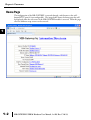
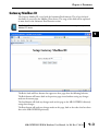
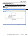
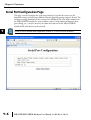
PARAMETERS
CHAPTER
4
In This Chapter...
Home Page . . . . . . . . . . . . . . . . . . . . . . . . . . . . . . . . . . . . . . . . . . . . . . . . . . . . . . . .4–2
Gateway Modbus ID . . . . . . . . . . . . . . . . . . . . . . . . . . . . . . . . . . . . . . . . . . . . . . . . .4–3
Module Name and Module Description . . . . . . . . . . . . . . . . . . . . . . . . . . . . . . . . . .4–4
IP Setup Configuration Page . . . . . . . . . . . . . . . . . . . . . . . . . . . . . . . . . . . . . . . . . .4–5
Serial Port Configuration Page . . . . . . . . . . . . . . . . . . . . . . . . . . . . . . . . . . . . . . . . .4–6
Setup Slave Timeout / Retries Page . . . . . . . . . . . . . . . . . . . . . . . . . . . . . . . . . . . . .4–7
Gateway Device Status Page . . . . . . . . . . . . . . . . . . . . . . . . . . . . . . . . . . . . . . . . . .4–8
Firmware Updates . . . . . . . . . . . . . . . . . . . . . . . . . . . . . . . . . . . . . . . . . . . . . . . . . .4–11
Chapter 4: Parameters
1
2
3
4
5
6
7
8
9
10
11
12
13
14
A
B
C
D
Home Page
4–2
The configuration of the MB-GATEWAY is accessed through a web browser at the wellknown HTTP port 80 (not configurable). The image below shows the home page that will
be displayed when the web server of the MB-GATEWAY module is accessed. From this page,
all of the different setup screens can be accessed.
MB-GATEWAY-USER-M Hardware User Manual, 1st Ed. Rev. C 10/13
Chapter 4: Parameters
Gateway Modbus ID
The Gateway Modbus ID is used with the Automatic Read function. This is how the local
data buffer is accessed by the Modbus Client device. The usage of this field will be explained
in more detail in the Automatic Read Function section.
The Modbus ID used in this field should be unique to the serial network and not assigned to any real
Modbus RTU device.
The Back, Send and Reset buttons that appear on these pages have the following behavior:
The Back button will browse back to the previous page viewed without saving any changes
made on the current page.
The Send button will Send any changes made on this page to the MB-GATEWAY, effectively
saving those changes.
The Reset button will undo any changes made on this page, back to the values that have been
Sent to the MB-GATEWAY previously.
MB-GATEWAY-USER-M Hardware User Manual, 1st Ed. Rev. C 10/13
1
2
3
4
5
6
7
8
9
10
11
12
13
14
A
B
C
D
4–3
Chapter 4: Parameters
1
2
3
4
5
6
7
8
9
10
11
12
13
14
A
B
C
D
Module Name and Module Description
4–4
These fields are used only for reference and identification when managing several different
MB-GATEWAY modules on a network.
MB-GATEWAY-USER-M Hardware User Manual, 1st Ed. Rev. C 10/13
Chapter 4: Parameters
IP Setup Configuration Page
The IP address, Subnet Mask and Default Gateway address can be configured on this page.
You may lose communications with the MB-GATEWAY module if you configure an IP address and/or
Subnet Mask that is not compatible with the subnet of your PC’s Network Interface Card. You may be
required to change the subnet settings of your PC or use the NetEdit tool to regain communications in
this situation.
MB-GATEWAY-USER-M Hardware User Manual, 1st Ed. Rev. C 10/13
1
2
3
4
5
6
7
8
9
10
11
12
13
14
A
B
C
D
4–5
Chapter 4: Parameters
1
2
3
4
5
6
7
8
9
10
11
12
13
14
A
B
C
D
Serial Port Configuration Page
4–6
This page is used to configure the serial port parameters if you do not want to use the
dipswitch settings or if baud rates different than the dipswitch settings range are desired. The
serial port settings should match the settings of the Modbus RTU serial nodes connected to
the MB-GATEWAY module. In some situations, such as a high amount of electrical noise,
poor cabling, etc., it may be necessary to reduce the baud rate on the MB-GATEWAY
module AND serial devices on the network.
In order to use the software based configuration, switches S0, S1, and S2 must be turned OFF.
MB-GATEWAY-USER-M Hardware User Manual, 1st Ed. Rev. C 10/13
Chapter 4: Parameters
Set Up Slave Timeout / Retries Page
The “Set Up Slave Timeout/Retries” page is used to configure the timing on the serial side of
the MB-GATEWAY module. By default, all serial requests will use the “Default Timeout”
value and “Default Retries” value. If there are devices on the serial network that require
different timing adjustments, those exception cases can be added to the table below. Simply
specify the node ID, the timing value and retry count necessary for that device.
The way that the timeout and retry field is utilized is:
The MB-GATEWAY will send a request to the serial device, if there is no reply from the
device within the Timeout value specified, the MB-GATEWAY will send another request and
wait again. It will do this for the number of times specified in the Retry field. Once the MBGATEWAY has attempted to access the device for the number of retry counts specified and
no reply is forthcoming, the MB-GATEWAY will respond with an exception error: 04 (Slave
device failure).
The “Inter-packet TX Delay” field specifies how long between serial requests the
MB-GATEWAY module should wait . This applies to all serial requests to all serial devices on
the serial side of the module.
MB-GATEWAY-USER-M Hardware User Manual, 1st Ed. Rev. C 10/13
1
2
3
4
5
6
7
8
9
10
11
12
13
14
A
B
C
D
4–7
Chapter 4: Parameters
1
2
3
4
5
6
7
8
9
10
11
12
13
14
A
B
C
D
Gateway Device Status Page
4–8
The Gateway Device Status page contains statistical information about the MB-GATEWAY
module that can be used to gauge the performance of the communications and to
troubleshoot communications.
MB-GATEWAY-USER-M Hardware User Manual, 1st Ed. Rev. C 10/13
Chapter 4: Parameters
� Automatic Reads
This table shows statistical information about the requests being sent when the Automatic
Read function is being utilized. This information can help to indicate whether this table has
been configured correctly or not.
Table Item: Corresponds to the position in the table of the “Set Up Automatic Reads” page.
Error Count: Indicates how many error requests have occurred for that table item. This could be a
timeout error or an exception response.
Last Error: Indicates the error code from the last error request. If the device fails to respond
(Timeout), the error “Slave Device Failure” will be shown in this field.
Retries: Indicates how many retries have occurred. It is a cumulative value and does not reset unless
the module has been power cycled or the “Clear Values” button at the bottom has been
pressed.
Timeout: Indicates how many times a request has not received a reply within the specified timeout
period. It is a cumulative value and does not reset unless the module has been power
cycled or the “Clear Values” button at the bottom has been pressed.
Number Completed: Indicates how many requests have been sent for that table item.
� Last Modbus TCP Request
This table shows statistical information about the last request that was received on the
Modbus TCP side from a Modbus TCP Client device.
Slave Number: Indicates the “Unit ID” number within the Modbus TCP header of the Modbus
TCP request.
Function: Indicates the Modbus function requested within the Modbus TCP request.
Reference: Indicates the starting address requested within the Modbus TCP request. The
“Reference” value is the offset from 0. More information will be explained in the
Automatic Read Function section as to how this Reference value corresponds to a
Modicon style address that is found in many Modbus devices.
Count: Indicates the number of Registers, Coils or Bits requested within the Modbus TCP request.
Data: This field indicates the Data values written to the MB-GATEWAY module when a Write
function has been sent from the Modbus TCP Client device.
Status: Indicates the action taken by the MB-GATEWAY module upon receiving the Modbus TCP
Client request.
Found in cache = If the Modbus TCP Client request is targeted to the MB-GATEWAY
Module’s Modbus ID and the request corresponds with an address mapped in
the Automatic Read Function, the MB-GATEWAY module will respond with
the data from its local cache. The MB-GATEWAY module will also return
the data from its local cache if the TCP Client request corresponds with a
node number and address that has been configured in the Automatic Read
function table.
Completed = If the request does not meet the criteria explained above, a serial request is created.
Return: This field will indicate whether an error has occurred or not. If this field displays “No
Error”, the request was successful. Otherwise, the Modbus error text will be shown. Refer
to the Modbus specifications error code lists for detailed explanations of each error code.
MB-GATEWAY-USER-M Hardware User Manual, 1st Ed. Rev. C 10/13
1
2
3
4
5
6
7
8
9
10
11
12
13
14
A
B
C
D
4–9
Chapter 4: Parameters
� Last Modbus RTU Request
1
2
3
4
5
6
7
8
9
10
11
12
13
14
A
B
C
D
4–10
This table shows the last Modbus RTU request formed by the MB-GATEWAY module based
upon the Modbus TCP Client request received on the Ethernet side.
Slave Number: This is the Node number that was targeted in the last Modbus RTU serial request.
Function: Indicates the Function Code sent to the Modbus serial device in the last request.
Reference: Indicates the starting address requested within the Modbus RTU request. The
“Reference” value is the offset from 0. More information will be explained in the
Automatic Read Function section as to how this Reference value corresponds to a
Modicon style address that is found in many Modbus devices.
Count: Indicates the number of Registers, Coils or Bits requested within the Modbus RTU request.
Data: This field indicates the Data values written to the Modbus RTU device when a Write function
has been sent.
Status: Indicates the action taken by the MB-GATEWAY module on the Modbus RTU side.
Waiting for Header = This indicates that the MB-GATEWAY module has sent a request and is
waiting for the Reply.
Timeout = If a request was sent to a Modbus RTU device and no reply is received, this message
will appear.
Completed = If the request was sent and a reply was received, this message will show in the
Status field.
Return: This field will indicate whether an error has occurred or not. If this field displays “No
Error”, the request was successful. Otherwise, the Modbus error text will be shown. Refer to
the Modbus specifications error code lists for detailed explanations of each error code.
� Status Information
This table shows a summary of the current session (since power cycle or Clear Values button
selected). Comparing Requests to Cache Hits can help indicate whether the Automatic Reads
are configured to maximize efficient communications. And total Error, Retry and Timeout
data can indicate health of communications.
Setup Automatic Read Page
The Automatic Read Feature is explained in detail in Chapter 5: Automatic Read Feature.
MB-GATEWAY-USER-M Hardware User Manual, 1st Ed. Rev. C 10/13
Chapter 4: Parameters
Firmware Updates
This link sends you to Host Engineering’s website to retrieve the latest firmware for the
MB-GATEWAY module. The NetEdit tool is required to upgrade firmware in the
MB-GATEWAY module. The steps are shown below:
Open the NetEdit software. You may allow the NetEdit software to download the latest
firmware for the MB-GATEWAY module by clicking on File-> Live Update.
Once you have the firmware file to load into the MB-GATEWAY module, click on the Scan
Network button at the top left to browse for the MB-GATEWAY module that is in the
subnet of the PC.
Click on the GATEWAY module that you wish to upgrade and then select the “General
Settings” tab at the bottom of the screen. Click on the “Update Firmware” button in the
“General Settings” tab. You will get a dialog box to select the firmware file that you wish to
upgrade to. Select the correct file and click on the “Open” button.
Firmware Updates continued on the next page.
MB-GATEWAY-USER-M Hardware User Manual, 1st Ed. Rev. C 10/13
1
2
3
4
5
6
7
8
9
10
11
12
13
14
A
B
C
D
4–11
Chapter 4: Parameters
1
2
3
4
5
6
7
8
9
10
11
12
13
14
A
B
C
D
4–12
Confirm that you wish to perform the upgrade by clicking on the “Yes” button.
Once the process is complete, you will receive a dialog confirming success.
MB-GATEWAY-USER-M Hardware User Manual, 1st Ed. Rev. C 10/13