1
APPLICATION NOTE
M16C/26
Implementing Real Time Clock and WAIT Mode
1.0 Abstract
The following article describes the implementation of a low-power, real time clock using the sub-clock circuit with
a 32.768 kHz crystal and Wait mode of the M16C/26 microcontroller (MCU).
2.0 Introduction
This article shows how to use the M16C/26 MCU’s WAIT mode and implement a real time clock function on the
M16C/26 MCU using a 32.768KHz crystal on the sub-clock circuit.
The Renesas M16C/26 is a 16-bit MCU based on the M16C/60 CPU core. It has multiple peripherals such as
10-bit A/D, UARTs, clock circuits, etc.
There are three oscillator circuits in the M16C/26, which includes a main clock circuit, a sub-clock circuit, and an
on-chip oscillator. After a reset, the MCU always starts running from the main clock, which is usually used in
normal operation. The on-chip oscillator is an internal oscillator, which can be used in case the main clock stops.
The sub-clock, which needs to be enabled after reset, is a low frequency clock, that is useful for power reduction
and as a low speed clock source for timers and other peripherals. Using a 32.768KHz crystal in the sub-clock
circuit, a one-second timer can be generated and a real time clock (RTC) function is easily implemented.
The M16C/26 has two low power modes of operation, STOP mode and WAIT mode. When placed in STOP
mode all oscillation circuits are stopped and the MCU remains in the STOP state until an external interrupt or
Reset occurs. In WAIT mode, the clock that drives the MCU core logic, BCLK, is switched from the main clock to
the sub-clock circuit to lower power consumption. The peripheral clocks can be stopped, but not the sub-clock
oscillator divided by 32 (fc32), to further lower power consumption. Similar to STOP mode, an interrupt or a reset
is required to exit from WAIT mode.
A demo program for the MSV30262-SKP was developed to show the RTC-WAIT implementation.
3.0 Real-Time Clock Setup and Implementation
3.1 Sub-Clock Block and Hardware
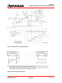
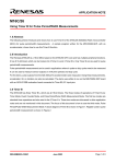
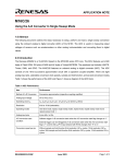
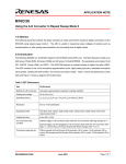
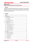
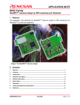
Figure 1 shows the block diagram of the M16C/26 clock generating circuit. Figure 2 shows examples on how to
wire the sub-clock pins to a crystal or an oscillator. The sub-clock circuit generates two signals internally, fc and
fc32 (fc/32), and can be used as a clock source for the different M16C/26 MCU peripherals. A 32.768KHz crystal
is connected to the sub-clock pins on the MSV30262 Board.
REU05B0044-0101Z
Sept 2004
Page 1 of 16
M16C/26
Implementing Real Time Clock and WAIT Mode
Figure 1 M16C/26 Clock Circuit Block Diagram
Figure 2 Connecting to Sub-clock Pins
REU05B0044-0101Z
Sept 2004
Page 2 of 16
M16C/26
Implementing Real Time Clock and WAIT Mode
3.2 Enabling the Sub-clock Circuit
As mentioned earlier, the sub-clock oscillation circuit is disabled after reset. To be able to use the sub-clock
circuit, it needs to be enabled. The steps necessary to enable the sub-clock circuit are listed below and followed
by sample code listing used in the demo.
1. Change Ports 8_6 (XCin) and 8_7 to inputs.
// Start the 32Khz crystal sub clock
pd8_7 = 0;
// setting GPIO to inputs (XCin/XCout)
pd8_6 = 0;
2. Disable protection of clock control register.
prc0 = 1;
/* Unlock CM0 and CM1 */
3. Enable sub-clock circuit.
cm04 = 1;
// Start the 32KHz crystal
4. Enable protection of clock control register.
prc0 = 0;
// Lock the System Clock Control Register
3.3 Setting up the Real Time Clock Timer
Now that we have enabled the sub-clock circuit, we need to setup the second timer that will run the real-time
clock function. As mentioned above, the sub-clock circuit generates fc and fc32. fc is the frequency of the crystal
or oscillator connected to the sub-clock pins. On the other hand, fc32 is fc divided by 32. On the MSV30262
Board, a 32.768 KHz crystal is connected between Xcin and Xcout, making fc equal to 32.768KHz. The
frequency fc32 then becomes, 1.024KHz.
A sample code, used in the demo, on setting up a timer (i.e. Timer B1) on the M16C/26 as the real-time clock
timer is shown below.
/* Configure Timer B1 - RTC (second) timer*/
tb1mr = 0xc0;
// Timer mode, fc32 (32.768KHz/32 = 1024Hz)
tb1 = 1023; // Set the counter to interrupt every second (1s = 1024 (0-1023) count).
Timer B1 is used in timer mode with fc32 as the clock source. In Timer mode the timer will count down every fc32
from a preset value (tb1) until it underflows. When the timer underflows it will generate an interrupt request and
reload the preset value into the count register. It will then begin counting down again.
REU05B0044-0101Z
Sept 2004
Page 3 of 16
M16C/26
Implementing Real Time Clock and WAIT Mode
To generate a 1-second timer, Timer B1 count (tb1) must be set to count 1024 (1 second x fc32). But since the
counter goes to 0, setting tb1 to 1023 will generate a 1024 count. The demo uses a 1 second timer but it can be
setup as a 1-minute timer by setting tb1 to 61440 (60 seconds x fc32).
Once the timer is setup, setting the start flag (i.e. tb1s) to 1 will start the timer running. For the demo, the timer
was not started until the clock has been preset.
3.4 The Real-time Clock Interrupt Routine
An interrupt is generated, every second, every time our timer underflows. And so, time must be calculated every
time this interrupt routine is called. A sample code that calculates time in military time format is shown below.
/*****************************************************************************
Name:
rtc_int
Parameters:
None
Returns:
None
Description: This is the RTC timer, Timer B1, interrupt routine. It is called
every second.
*****************************************************************************/
void rtc_int(void)
{
unsigned int i;
/* time calculation (in military time mode) */
if (++second >= 60){
second = 0;
if (++minute >= 60){
minute = 0;
++hour;
if (hour > 23)
hour = 0;
}
}
To tell the C compiler that the routine is an interrupt routine, a ‘# pragma interrupt /B irq_rtn’ must be defined
and where irq_rtn is the routine to be processed when the interrupt is generated. A sample definition used in the
demo, and can be found in rtc.c, is shown below.
/* interrupt routine used for rtc - vectors modified in sect30_rtc.inc */
#pragma INTERRUPT /B rtc_int
To be able to jump to this rtc_int routine, the M16C/26 MCU needs to know its vector address. The vector is set
in an include file, sect30.inc (in the demo, sect30_rtc.inc).
Please see sample snippet below used in
sect30_rtc.inc on how to setup the interrupt vector for our real time clock timer.
REU05B0044-0101Z
Sept 2004
Page 4 of 16
M16C/26
Implementing Real Time Clock and WAIT Mode
.lword
.lword
.lword
.lword
.lword
.lword
.glb
.lword
.lword
.lword
dummy_int
dummy_int
dummy_int
dummy_int
dummy_int
dummy_int
_rtc_int
_rtc_int
dummy_int
dummy_int
;
;
;
;
;
;
TIMER
TIMER
TIMER
TIMER
TIMER
TIMER
A0
A1
A2
A3
A4
B0
(for
(for
(for
(for
(for
(for
user)
user)
user)
user)
user) (vector 25)
user) (vector 26)
; TIMER B1 (for user) (vector 27)
; TIMER B2 (for user) (vector 28)
; INT0 (for user) (vector 29)
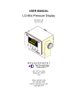
Start rtc_int()
Calculate
Time
brd_mode =
RUNNING
N (brd_mode = WAIT)
Y
Demo Heartbeat
Blink Red LED*
(every second)
Sequential LED
display count
Decrement
on_time counter
on_time <=
0 (zero)
N
Y
brd_mode =
GO_TO_WAIT
Return from Irq
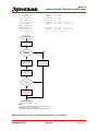
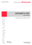
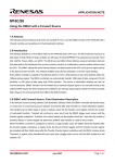
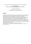
NOTE:
1. Functions called are in blue letters. See rtc.c for details.
2. Board mode are shown in red letters.
3. Blinking Red LED is to show that a program is running.
Figure 3 Real-time clock timer (Timer B1) interrupt routine, rtc_int(), flowchart
REU05B0044-0101Z
Sept 2004
Page 5 of 16
M16C/26
Implementing Real Time Clock and WAIT Mode
3.5 WAIT Mode and Real-time Clock
In many applications the real-time clock is required to operate under very low power conditions. This can be
accomplished by using a timer and the fc32 clock as the count source. The fc32 clock allows very low power
operation by allowing the MCU to operate in WAIT mode with all peripherals except those supplied with the fc32
clock to be disabled.
In the demo, the real-time clock timer B1 is used in Timer mode to generate an interrupt every second. After the
interrupt routine is serviced, the M16C/26 goes into WAIT mode. Every second, the real-time clock timer B1
interrupt occurs and triggers the M16C/26 out of WAIT mode, the timer B1 interrupt routine is serviced, and then,
the M16C/26 goes back to WAIT mode. As a note, an interrupt (or a reset) is required to bring the M16C/26 back
from a WAIT mode and so ensure that interrupts are enabled and the interrupt routine is set.
3.6 Entering WAIT Mode
When the WAIT instruction is executed, the BCLK stops and the M16C/26 go into WAIT mode. If the WAIT
Peripheral Function Clock Stop bit, CM02, is set the peripheral device clocks are also stopped. The oscillation
circuits continue to operate in WAIT mode. To minimize power requirements, the sub-clock can be selected as
the system clock and the main clock oscillation circuit is stopped. When the sub-clock is selected as the system
clock, the Peripheral Function Clock Stop bit should not be set to 1. The basic steps to enter WAIT mode are
shown below.
1. Disable protection of the clock control registers.
prc0 = 1;
2. Switch the system clock to the sub-clock.
cm07 = 1;
3. To reduce the power requirement, stop the main clock.
cm05 = 1;
4. Enable protection of the clock control registers.
prc0 = 0;
5. Call the WAIT instruction.
asm (“wait”);
In the demo, the wait_setup() function routine, shown below, makes the preparation for WAIT mode but does
NOT execute the WAIT instruction. The WAIT instruction is executed in the main() loop List 1. For demo
purposes, aside from the real-time clock timer interrupt, another interrupt (a key input interrupt) was added to
allow the M16C/26 to exit WAIT mode. Pressing one of the three user pushbuttons S2, S3, or S4 on the
MSV30262 Board generates a key input interrupt. The key input interrupt routine (wakeup_int()) must also be
defined similar to the real-time clock timer B1 interrupt routine.
REU05B0044-0101Z
Sept 2004
Page 6 of 16
M16C/26
Implementing Real Time Clock and WAIT Mode
/*****************************************************************************
Name:
wait_setup
Parameters:
None
Returns:
None
Description: This prepares the MCU to enter wait mode. The application/demo runs
and after a preset period, goes into wait mode.
Aside from the real-time clock timer B1, the MCU can come out of
wait mode by user intervention: pressing one of the three user
pushbuttons S2-S4 (key input irq).
The key input irq to wake MCU must be set prior to wait mode so
it can be used to wakeup the MCU. This is disabled in the wakeup
interrupt routine.
*****************************************************************************/
void wait_setup(void)
{
/* save power */
ALL_LED_OFF;
// all LEDs off
disp_ctrlw(LCD_CLEAR);
// clear LCD
/* enable key input irq */
asm("FCLR I");
kupic = 6;
asm("FSET I");
// disable interrupts
// enable key-input irq
// enable interrupts
/* Switch to XCin and then turn Xin off before going to wait mode */
prc0 = 1;
// unlock CM0
cm07 = 1;
// Switch from Xin to XCin
cm05 = 1;
// Stop Xin
prc0 = 0;
// lock CM0
/* set our board mode to wait */
brd_mode = WAIT;
}
WARNING:
The WAIT instruction should never be called from within an interrupt handler. Calling a WAIT
instruction within an interrupt routine may cause unexpected clock or MCU behavior. Ensure that the interrupt
that will allow the M16C/26 MCU to exit is enabled. Otherwise, the MCU will be stuck in WAIT mode.
while(1){
// infinite loop
if (brd_mode == RUNNING){
led_display(disp_count);
if (temp_sec != second){
// in RUNNING mode?
// display current count
// LCD is to be updated every second
only
display(0, "RTC Time");
disp_time(2);
temp_sec = second;
// RTC Header
// current time
}
REU05B0044-0101Z
Sept 2004
Page 7 of 16
M16C/26
Implementing Real Time Clock and WAIT Mode
}
else if (brd_mode == GO_TO_WAIT)
wait_setup();
// time to go wait mode?
// yes, let's prepare for wait mode
else{
// let's wait here (brd_mode =
WAIT)
asm("WAIT");
asm("NOP");
// in wait mode
// 4 NOPs required
asm("NOP");
asm("NOP");
asm("NOP");
// due to prefetch queue
after
wait
instruction
}
}
List 1 Executing a Wait Instruction
3.7 Exiting WAIT mode
The MCU will exit WAIT mode when an interrupt or a reset occurs. After exiting WAIT mode the MCU will enter
the interrupt service routine for that interrupt. After completion of the service routine the MCU will return to the
instruction following the WAIT instruction.
In the demo, there are two interrupts that will allow us to exit WAIT mode. One is the RTC interrupt service
routine which occurs every second. The second is using a key-input interrupt by pressing one of the three user
pushbuttons. The RTC interrupt is enabled during initialization and always remain enable. The key-input interrupt
is enabled in the wait_setup() routine before the WAIT instruction is executed.
4.0 The RTC (and Wait) Demo Program
The RTC-Wait demo program implemented all the topics discussed earlier. For demo purposes, the MSV30262
Board was used. Like any other clock, the current time must be preset before running the clock. The clock is
displayed on the LCD and the LED’s are blinking sequentially. After 10s, the LCD and LED’s are switched off to
lower power consumption. Every second, as the real-time clock timer B1 interrupt is generated, the Red LED is
blinked so that it’s visible that a program is running. Pressing one of the user pushbuttons S2, S3, or S4, will
display the current time on the LCD and blink the LED’s sequentially for 10s.
4.1 Setting Initial Time
After the RTC-Wait program has been downloaded, run the program. Banners are displayed and then Set Hour
will be displayed on the LCD. Pressing S2 will increment the hour while pressing S3 will decrement the hour.
After the hour has been set, press S4 to set the minutes. Similar to setting the hour, pressing S2 will increment
minutes and pressing S3 decrements minutes. After minutes have been set, pressing S4 will start the clock.
Preset time is displayed on the LCD and the LED’s will be blinking sequentially. After 10s, LCD will be blank and
the heartbeat Red LED blinks every second.
REU05B0044-0101Z
Sept 2004
Page 8 of 16
M16C/26
Implementing Real Time Clock and WAIT Mode
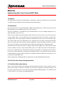
Start
Initalize brd_mode to
RUNNING
Initialize Sub-clock &
Real-Time Clock Timer
rtc_init()
Preset Clock
set_time()
Start Real-time Clock
Timer
brd_mode =
RUNNING
Display
Current Time
disp_time()
Y
N
brd_mode =
GO_TO_WAIT
Prepare for
WAIT mode
(switch to
sub-clock)
wait_setup()
Y
N
MCU in WAIT mode
brd_mode = WAIT
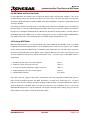
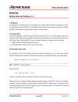
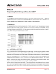
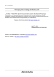
NOTE:
1. Functions called are in blue letters. See rtc.c for details.
2. Board mode are shown in red letters.
Figure 4 RTC-Wait Demo Program Flowchart
REU05B0044-0101Z
Sept 2004
Page 9 of 16
M16C/26
Implementing Real Time Clock and WAIT Mode
4.2 Displaying Current Time on LCD
Pressing any of the user pushbuttons S2, S3, or S4, will display the current time on the LCD and cause the
sequential blinking of the three LED’s for 10s.
5.0 Conclusion
Real-time clock function is easily implemented in the M16C/26 MCU using any of its eight 16-bit timers. Some
real-time clock function requires power conservation and can also be accomplished with the M16C/26 MCU by
using WAIT mode.
6.0 Reference
Renesas Technology Corporation Semiconductor Home Page
http://www.renesas.com
E-mail Support
[email protected]
Data Sheets
• M16C/26 datasheets, M30262eds.pdf
User’s Manual
• M16C/20/60 C Language Programming Manual, 6020c.pdf
• M16C/20/60 Software Manual, 6020software.pdf
• Interrupt Handler App Note, M16C26_Interrupt_Handlers_in_C.doc
• MSV30262-SKP Users Manual, Users_Manual_MSV30262.pdf
REU05B0044-0101Z
Sept 2004
Page 10 of 16
M16C/26
Implementing Real Time Clock and WAIT Mode
7.0 Software Code
The rtc.c code used in the demo program is shown below. The whole source code/TM project for the RTC-WAIT
demo can be requested from the your Renesas representative.
/**********************************************************************
*
*
File Name: rtc.c
*
*
Content: Real Time Clock (RTC) functions for M16C that includes setting
*
initial time, displaying time, RTC, and wakeup interrupt routines.
*
*
Revision 1.1 2003-02-21
***********************************************************************/
#include "..\common\sfr262.h"
#include "..\common\skp26.h"
#include "rtc.h"
// M16C/26 special function register definitions
// MSV30262-SKP function definitions
// RTC function definitions
/* interrupt routine used for rtc - vectors modified in sect30_rtc.inc */
#pragma INTERRUPT
rtc_int
#pragma INTERRUPT
wakeup_int
#define RUN_TIME
in seconds
10
// preset demo run time before going into wait mode -
int hour, minute, second;
char on_time;
char brd_mode;
//
//
//
//
//
//
clock variables
demo run time and sleep time
Mode:
Running - RTC displayed on LCD, LEDs flashing sequentially
Go to Wait - Preparation for wait mode
Wait - No LCD and LEDs, RTC Running
const char num_to_char[10] = {'0','1','2','3','4','5','6','7','8','9'};
extern char disp_count;
/*****************************************************************************
Name:
init_rtc
Parameters:
none
Returns:
none
Description: Initialize the real-time clock (RTC).
*****************************************************************************/
void init_rtc(void){
/* Change XCin and XCout to inputs and start the 32Khz crystal sub clock
pd8_7 = 0;
// setting GPIO to inputs (XCin/XCout)
pd8_6 = 0;
prc0 = 1;
cm04 = 1;
prc0 = 0;
REU05B0044-0101Z
*/
// Unlock CM0 and CM1
// Start the 32KHz crystal
// Lock the System Clock Control Register
Sept 2004
Page 11 of 16
M16C/26
Implementing Real Time Clock and WAIT Mode
/* Configure Timer B1 - RTC (second) timer*/
tb1mr = 0xc0;
// Timer mode, fc32 (32.768KHz/32 = 1024Hz)
tb1 = 1023;
// Set the counter to interrupt every second (1s = 1024 (0-1023) count).
}
/*****************************************************************************
Name:
set_time
Parameters:
none
Returns:
none
Description: Presets clock and starts clock (RTC).
*****************************************************************************/
void set_time(void){
char set_flag = 1;
// variable to go to next setting by pressing S4
// 1 - set hour, 2 - set minute, 3 - run RTC
/* initialize clock variables */
hour = 0;
minute = 0;
second = 0;
while (set_flag < 3) {
/* set Hour */
if (set_flag == 1){
if(!S_S2){
// incrementing variable everytime S2 is pressed
while(!S_S2);
// wait for S2 to go back up
if (++hour > 23)
// max hour 12 (12 PM)
hour = 0;
disp_time(2);
}
if(!S_S3){
// decrement variable everytime S3 is pressed
while(!S_S3);
// wait for S3 to go back up
if (--hour < 0) // min hour 0 (0 AM)
hour = 23;
disp_time(2);
}
if (!S_S4){
// move to next setting (minutes) if S4 is pressed
while(!S_S4);
// wait for S4 to go back up
set_flag = 2;
// set minutes
}
}
/* set Minutes */
if (set_flag == 2){
display(0, "Set Min "); // display Set Minute
if(!S_S2){
// incrementing variable everytime S2 is pressed
while(!S_S2);
// wait for S2 to go back up
if (++minute > 59)
// max minute 59
minute = 0;
disp_time(2);
}
REU05B0044-0101Z
Sept 2004
Page 12 of 16
M16C/26
Implementing Real Time Clock and WAIT Mode
if(!S_S3){
// decrement variable everytime S3 is pressed
while(!S_S3);
// wait for S3 to go back up
if (--minute < 0)
// min minute 0
minute = 59;
disp_time(2);
}
if (!S_S4){
// move to next setting (run RTC) if S4 is pressed
while(!S_S4);
// wait for S4 to go back up
set_flag = 3;
// run RTC
}
}
}
/* clock has been preset, start RTC */
tb1s = 1;
/* set on_time */
on_time = RUN_TIME;
}
/*****************************************************************************
Name:
disp_time
Parameters:
LCD_Line
1 - display on Line 1 (top)
2 - display on Line 2 (bottom)
Returns:
none
Description: Displays time on LCD.
*****************************************************************************/
void disp_time(char LCD_Line){
unsigned char hr1_LCD,
characters for display
unsigned int clk_var;
hr2_LCD,
min1_LCD,
min2_LCD,
sec1_LCD,
sec2_LCD;
//
/* get hour to display */
clk_var = (unsigned int) hour/10;
hr1_LCD = num_to_char[clk_var];
hr2_LCD = num_to_char[(unsigned int) hour - (clk_var) * 10];
/* get minutes to display */
clk_var = (unsigned int) minute/10;
min1_LCD = num_to_char[clk_var];
min2_LCD = num_to_char[(unsigned int) minute - (clk_var) * 10];
/* get seconds to display */
clk_var = (unsigned int) second/10;
sec1_LCD = num_to_char[clk_var];
sec2_LCD = num_to_char[(unsigned int) second - (clk_var) * 10];
/* display time on LCD */
if (LCD_Line == 1)
disp_ctrlw(0x80);
else
disp_ctrlw(0xC0);
REU05B0044-0101Z
// top line of LCD, first char
// bottom line of LCD, first char
Sept 2004
Page 13 of 16
M16C/26
Implementing Real Time Clock and WAIT Mode
disp_dataw(hr1_LCD);
disp_dataw(hr2_LCD);
disp_dataw(':');
disp_dataw(min1_LCD);
disp_dataw(min2_LCD);
disp_dataw(':');
disp_dataw(sec1_LCD);
disp_dataw(sec2_LCD);
}
/*****************************************************************************
Name:
rtc_int
Parameters:
None
Returns:
None
Description: This is the RTC timer, Timer B1, interrupt routine. It is called
every second.
*****************************************************************************/
void rtc_int(void)
{
unsigned int i;
/* time calculation (in military time mode) */
if (++second >= 60){
second = 0;
if (++minute >= 60){
minute = 0;
++hour;
if (hour > 23)
hour = 0;
}
}
if (brd_mode == RUNNING){
++disp_count;
if (disp_count > 4)
disp_count = 1;
--on_time;
// in running mode?
// increment display counter
// decrement our on_time
if (on_time <= 0)
// time to go to wait mode?
brd_mode = GO_TO_WAIT; // if so, let's prepare for it
}
/* Make a heartbeat LED so it's visible that the program is running. */
/* This is only for demo purposes. For actual applications, you can */
/* omit this routine.
*/
else{
// in wait mode
RED_LED = 0;
// Flash Red LED
for (i = 0xFF; i > 0; i--);
// add some delay
RED_LED = 1;
// turn off Red LED
REU05B0044-0101Z
Sept 2004
Page 14 of 16
M16C/26
Implementing Real Time Clock and WAIT Mode
}
}
/*****************************************************************************
Name:
wakeup_int
Parameters:
None
Returns:
None
Description: This interrupt routine will wake us up from wait mode due to user
intervention by pressing any of the three user pushbuttons, S2-S4.
*****************************************************************************/
void wakeup_int(void)
{
unsigned int i;
/* wakeup from wait mode - turn Xin back-on*/
prc0 = 1;
// unlock CM0
cm05 = 0;
// Enable Xin
for (i = 0; i <= 0x0F; ++i)
asm ("NOP");
cm06 = 0;
cm07 = 0;
prc0 = 0;
// delay routine to allow Xin oscillator to stabilize
// No div - need to be set again - goes back to div by 8 in wait mode
// Switch from XCin to Xin
// lock CM0
/* disable key-input irq */
asm("FCLR I");
kupic = 0;
asm("FSET I");
// disable interrupts
// disable key input irq
// enable interrupts
/* switch brd_mode to RUNNING */
brd_mode = RUNNING;
/* reset our demo run time every time we wake up */
on_time = RUN_TIME;
}
/*****************************************************************************
Name:
wait_setup
Parameters:
None
Returns:
None
Description:
This prepares the MCU to enter wait mode. The application/demo runs
and after a preset period, goes into wait mode.
Aside from the real-time clock timer B1, the MCU can come out of
wait mode by user intervention: pressing one of the three user
pushbuttons S2-S4 (key input irq).
The key input irq to wake MCU must be set prior to wait mode so
it can be used to wakeup the MCU. This is disabled in the wakeup
interrupt routine.
*****************************************************************************/
void wait_setup(void)
{
/* save power */
REU05B0044-0101Z
Sept 2004
Page 15 of 16
M16C/26
Implementing Real Time Clock and WAIT Mode
ALL_LED_OFF;
disp_ctrlw(LCD_CLEAR);
// all LEDs off
// clear LCD
/* enable key input irq */
asm("FCLR I");
// disable interrupts
kupic = 6;
// enable key-input irq
asm("FSET I");
// enable interrupts
/* Switch to XCin and then turn Xin off before going to wait mode */
prc0 = 1;
// unlock CM0
cm07 = 1;
// Switch from Xin to XCin
cm05 = 1;
// Stop Xin
prc0 = 0;
// lock CM0
/* set our board mode to wait */
brd_mode = WAIT;
}
REU05B0044-0101Z
Sept 2004
Page 16 of 16
Keep safety first in your circuit designs!
• Renesas Technology Corporation puts the maximum effort into making semiconductor products
better and more reliable, but there is always the possibility that trouble may occur with them. Trouble
with semiconductors may lead to personal injury, fire or property damage.
Remember to give due consideration to safety when making your circuit designs, with appropriate
measures such as (i) placement of substitutive, auxiliary circuits, (ii) use of nonflammable material or
(iii) prevention against any malfunction or mishap.
Notes regarding these materials
• These materials are intended as a reference to assist our customers in the selection of the Renesas
•
•
•
•
•
•
•
Technology Corporation product best suited to the customer'
s application; they do not convey any
license under any intellectual property rights, or any other rights, belonging to Renesas Technology
Corporation or a third party.
Renesas Technology Corporation assumes no responsibility for any damage, or infringement of any
third-party'
s rights, originating in the use of any product data, diagrams, charts, programs, algorithms,
or circuit application examples contained in these materials.
All information contained in these materials, including product data, diagrams, charts, programs and
algorithms represents information on products at the time of publication of these materials, and are
subject to change by Renesas Technology Corporation without notice due to product improvements
or other reasons. It is therefore recommended that customers contact Renesas Technology
Corporation or an authorized Renesas Technology Corporation product distributor for the latest
product information before purchasing a product listed herein.
The information described here may contain technical inaccuracies or typographical errors.
Renesas Technology Corporation assumes no responsibility for any damage, liability, or other loss
rising from these inaccuracies or errors.
Please also pay attention to information published by Renesas Technology Corporation by various
means, including the Renesas Technology Corporation Semiconductor home page
(http://www.renesas.com).
When using any or all of the information contained in these materials, including product data,
diagrams, charts, programs, and algorithms, please be sure to evaluate all information as a total
system before making a final decision on the applicability of the information and products. Renesas
Technology Corporation assumes no responsibility for any damage, liability or other loss resulting
from the information contained herein.
Renesas Technology Corporation semiconductors are not designed or manufactured for use in a
device or system that is used under circumstances in which human life is potentially at stake. Please
contact Renesas Technology Corporation or an authorized Renesas Technology Corporation product
distributor when considering the use of a product contained herein for any specific purposes, such as
apparatus or systems for transportation, vehicular, medical, aerospace, nuclear, or undersea
repeater use.
The prior written approval of Renesas Technology Corporation is necessary to reprint or reproduce in
whole or in part these materials.
If these products or technologies are subject to the Japanese export control restrictions, they must be
exported under a license from the Japanese government and cannot be imported into a country other
than the approved destination.
Any diversion or reexport contrary to the export control laws and regulations of Japan and/or the
country of destination is prohibited.
Please contact Renesas Technology Corporation for further details on these materials or the
products contained therein.