1
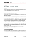
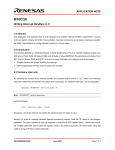
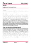
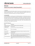
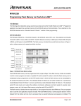
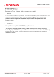
APPLICATION NOTE
M16C/26
Using Timer B for Pulse Period/Width Measurements
1.0 Abstract
The following article introduces and shows how to use Timer B of the M16C/26 (M30262) Flash microcontroller
(MCU) for pulse period/width measurements. A sample program written for the MSV30262-SKP, with an
accelerometer, shows how to use this Timer B function.
2.0 Introduction
The Renesas M16C/26 is a 16-bit MCU based on the M16C/60 CPU core and has multiple peripheral functions.
It has 8 16-bit timers which can be broken into 5 Timer A’s and 3 Timer B’s. Only Timer B can be used for pulse
period/width measurements.
Pulse period/width measurement can be used in applications where in pulse or duty cycles need to be measured.
It can be used to measure sensor outputs or verify time periods and duty cycle.
For the demo, pulse outputs from the ADI ADXL210 accelerometer were measured. Using these measurements,
acceleration, tilt, or vibration can also be calculated. The demo was written to run on the MSV30262-SKP board
with an ADXL210EB evaluation board connected to Timer B0, B1 input pins.
3.0 Timer B
The M16C/26 has three Timer B’s, which are all 16-bit timers. The three modes of operations of Timer B are:
Timer Mode, Event Counter Mode, and Pulse Period/Pulse Width Measurement Mode. The first two modes are
standard timer operations and also exist in the 5 Timer A’s. These two modes are discussed in other application
notes and are not mentioned in this document. The focus of this document is how to use the third mode, Pulse
Period/Pulse Width Measurement Mode. A block diagram of Timer B is shown in Figure 1. Register used in pulse
period/width measurement is shown in Figure 2.
REU05B0053-0100Z
June 2003
Page 1 of 9
M16C/26
Using Timer B for Pulse Period/Width Measurements
Figure 1 M16C/26 Timer B Block Diagram
Figure 2 Timer B Mode Register in Pulse Period/Width Measurement Mode
REU05B0053-0100Z
June 2003
Page 2 of 9
M16C/26
Using Timer B for Pulse Period/Width Measurements
3.1 Measurement Modes
There are three modes in which a pulse can be measured: falling edge-to-falling edge, rising edge-to-rising edge,
or rising edge-to-falling edge/falling edge-to-rising edge. The mode can be selected by setting bits 2 and 3 (MR0,
MR1) of the Timer B Mode register.
In the demo, two modes are used: rising edge-to-rising edge and rising edge-to-falling edge/falling edge-to-rising
edge. The rising edge-to-rising edge mode is used to measure one total cycle (period), t2. The rising
edge-to-falling edge/falling edge-to-rising edge mode is used to measure the ‘On’ time, t1, of the accelerometer.
When measuring the ‘On’ time of the accelerometer, the port pin where the pulse is connected is polled to
determine if the measurement should be used or discarded. The port pin is polled after the measurement is taken
(i.e. a Timer B interrupt has occurred). If the port pin is low, then the rising edge-to-falling edge (‘On’ time) is
measured is used. If the port pin is high (i.e. falling edge-to-rising edge), the measurement is discarded.
3.2 Count Source
There are four count sources to choose from: f1, f8, f32, or fc32. f1, f8, and f32 are clocks derived from the main
clock input, Xin. f1 is the frequency of the main clock, f8 is f1 divided by 8, and f32 is f1 divided 32. On the other
hand, fc32 is a clocked derived from the subclock input. fc32 is the frequency of the subclock, fc, divided by 32.
On the MSV30262 Board, f1 is 20MHz (f8=2.5MHz, f32=625KHz) and fc is 32.768KHz (fc32=1024Hz).
The importance of the count source is that, it determines the sampling rate of the measurement. For example, if
the pulse you need to measure is 1.5ms and you sample it every 1ms, you will miss the width by 0.5ms. If we
sample the pulse with every 0.1ms (100us), the pulse measurement will be close to 1.5ms. Figure 3 shows how
the sampling clock affects the accuracy of the pulse measurement. As can be seen on the figure, using a faster
sampling clock rate makes a more accurate pulse width measurement.
U nknow n
P u ls e
S lo w e r
S a m p lin g
C lo c k
P u ls e W id t h
M e a s u re d
U nknow n
P u ls e
F a s te r
S a m p lin g
C lo c k
P u ls e W id t h
M e a s u re d
Figure 3 Sampling Clock & Measurement Accuracy
REU05B0053-0100Z
June 2003
Page 3 of 9
M16C/26
Using Timer B for Pulse Period/Width Measurements
You might be thinking that we should use the fastest sampling clock so we can get the most accurate
measurement. We have to remember that the timer must be able to handle the count without overflowing when
we used a faster sampling clock. For example, in the demo, the total cycle of the pulse is about 4ms. f1, f8, and
f32 can be used as the sampling clock (but not fc32). Timer B is a 16-bit counter, if we used f1, the total count will
be 20MHz * 4ms which will be equal to 80,000. This count is beyond the 16-bit counter range (65,536). And so,
f8 was used for the demo.
/* Initialize Timer B0 for t2 measurement */
tb0mr = 0x46;
// f8, measure rising-to-rising edges,
// pulse period measurement mode
List 1 Timer B Mode Register Initialization for Pulse Period Measurement
/* now that we have t2, let's set switch both timers to measure t1, rising-to-falling edges (or falling-to-rising edges) */
tb0mr = 0x4A;
// f8, measure rising-to-rising edge, PM mode
tb1mr = 0x4A;
// f8, measure rising-to-rising edge, PM mode
List 2 Timer B Mode Register Initialization for Pulse Width Measurement
3.3 Interrupts
When taking pulse period/width measurements, interrupts occur after the period or pulse has been measured
and is dependent on the mode selected. If using rising edge-to-rising edge mode, the interrupt is generated
during the first rising edge of the count source (sampling clock) after the second rising edge of the pulse is
detected. If using rising edge-to-falling edge/falling edge-to-rising edge mode, the interrupt is generated on the
next rising edge of the count source for every rising or falling edge of the pulse.
4.0 Pulse Period/Width Measurement Demo Program
The demo program was written to run on the MSV30262-SKP board with Analog Device’s ADXL210EB
Evaluation Board connected to the M16C/26’s Timer B input pins. The ‘On’ time period of the dual axis
accelerometer is shown on the LCD. The LCD display is updated every 2 seconds. X-axis PM, in milliseconds
(ms), is shown on the upper line while the Y-axis PM is displayed on the lower line of the LCD. Tilting the board
sideways, X- or Y-axis, will change the pulse period displayed. Further modifications of the program will allow
acceleration, tilt, vibration, or duty cycle measurements.
If
you
have
an
MSV30262-SKP,
a
copy
of
the
source
files
can
be
found
under
the
C:\MTOOL\MSV30262-SKP\Sample_Code\PulsMsmt folder after MSV30262-SKP software installation. The
program was compiled using the KNC30 Compiler, which also came with the MSV30262-SKP. It can be modified
to suit a user application.
REU05B0053-0100Z
June 2003
Page 4 of 9
M16C/26
Using Timer B for Pulse Period/Width Measurements
5.0 Conclusion
Pulse Period/Width Measurement mode on the M16C/26 MCU allows a simple method of measuring pulse
periods or duty cycles. It can be used in applications where time periods, duty cycles, etc., needs to be
measured.
6.0 Reference
Renesas Technology Corporation Semiconductor Home Page
http://www.renesas.com
E-mail Support
[email protected]
Data Sheets
• M16C/26 datasheets, M30262eds.pdf
User’s Manual
• M16C/20/60 C Language Programming Manual, 6020c.pdf
• M16C/20/60 Software Manual, 6020software.pdf
• Interrupt Handler App Note, M16C26_Interrupt_Handlers_in_C.doc
• MSV30262-SKP Users Manual, Users_Manual_MSV30262.pdf
7.0 Software Code
The pulse period/width measurement demo routines (in pulsmsmt.c) are shown below. The complete project,
written in C, can be compiled/linked using the KNC30 compiler and will be provided upon request. Please contact
your Renesas representative for details.
/**********************************************************************
*
*
File Name: pulsmsmt.c
*
*
Content: Pulse period/width measurement functions for M16C/26 that includes
*
Timer B initialization and interrupt service routines.
*
*
Revision 1.1 2003-02-21
***********************************************************************/
#include "..\common\sfr262.h"
#include "..\common\skp26.h"
#include "pulsmsmt.h"
REU05B0053-0100Z
// M16C/26 special function register definitions
// MSV30262-SKP function definitions
// PM function definitions
June 2003
Page 5 of 9
M16C/26
Using Timer B for Pulse Period/Width Measurements
/* Timer B0 & B1 irq routines used - vectors modified in sect30_pm.inc */
#pragma INTERRUPT
tb0_int
#pragma INTERRUPT
tb1_int
unsigned int t2;
unsigned int t1_tb0, t1_tb1;
falling edge)
// t2 period (one total cycle - rising edge to rising edge)
// t1 pulse ('ON' portion of the total cycle (rising edge to
char tb0_flag, tb1_flag = 0;
// indicator if Timer B0 or B1 interrupt has occurred
extern char brd_mode;
// Mode:
//
INIT
: PWM Initialization
//
RUNNING
: App running
//
HOLD
: measurements are on-hold
/*****************************************************************************
Name:
init_pm
Parameters:
none
Returns:
none
Description: PM initialization routine.
For this demo, two timers are used since the accelerometer is
dual axis (X & Y). Timer B1 is used for the X-axis and Timer B0
is used for the Y-axis.
*****************************************************************************/
void init_pm(void){
/* set timer B0 (P9_0) and B1 (P9_1) GPIO ports to inputs, P93 for self test to output */
prc2 = 1;
// P9 is write protected - disable protection before writing to P9
pd9_0 = 0;
// set to timer B0 input
pd9_1 = 0;
// set to timer B1 input
pd9_2 = 1;
// unused - set to output
p9_3 = 0;
// accelerometer self test - off
pd9_3 = 1;
// set to output - accelerometer self test
prc2 = 0;
// Write protect P9
/* Initialize brd_mode to PWM initialization */
brd_mode = INIT;
/* measure t2, the width of one cycle, on both timers. t2 is used for calculation */
get_t2();
/* set our brd_mode to running */
brd_mode = RUNNING;
}
/*****************************************************************************
Name:
get_t2
Parameters:
none
Returns:
none
Description: Gets the width of one cycle, t2, and stores it in memory to be used
for calculation later.
REU05B0053-0100Z
June 2003
Page 6 of 9
M16C/26
Using Timer B for Pulse Period/Width Measurements
t2 is measured using timer B0 as it is the same for both X and Y
channels (see ADXL210 datasheet for details). Timer B0 is initialized
to measure rising edge to rising edge.
By doing this, we will be able
to measure one cycle (T2), which will be used for later calculation.
f8 is used because it provides high resolution for measuring our
pulses (about 5ms cycles). f1 is too high that our 16-bit counter
will always time out. f32/fc32 can be used but may not provide
enough resolution.
After measuring t2, the timers are reconfigured for measuring t1,
i.e. measure rising edge to falling edge.
While the app is running, it is called to compensate for error due
to temperature.
*****************************************************************************/
void get_t2(void){
char second_t2 = 0;
// indicator for second measurement of t2.
// 1st irq is indeterminate so we have to wait
// for the second one
/* disable interrupts before we change timer configuration */
asm("FCLR I");
// disable interrupts
tb0ic = 0;
// disable timer B0 irq
tb1ic = 0;
// disable timer B1 irq
asm("FSET I");
// enable interrupts
tb0s = 0;
// stop timer B0
/* Initialize Timer B0 for t2 measurement */
tb0mr = 0x46;
// f8, measure rising-to-rising edges,
// pulse width measurement mode
/* enable timer B0 irq only (timer B1 irq remain disabled) for t2 measurement */
asm("FCLR I");
// disable interrupts
tb0ic = 6;
// enable timer B0 irq only
asm("FSET I");
// enable interrupts
tb0s = 1;
// start timer B0
brd_mode = INIT;
// change brd_mode to INIT for T2 measurement
/* measure t2 for timer B0 */
while (second_t2 < 2){
// make two measurements and use the second one
while (tb0_flag == 0); // wait for the interrupt and t2_tb0 measurement
++second_t2;
// increment our second measurement indicator
tb0_flag = 0;
// initialize flag and wait for second interrupt
}
tb0s = 0;
// stop timer B0
/* disable interrupts before we change timer configuration */
asm("FCLR I");
// disable interrupts
tb0ic = 0;
// disable timer B0 irq
asm("FSET I");
// enable interrupts
REU05B0053-0100Z
June 2003
Page 7 of 9
M16C/26
Using Timer B for Pulse Period/Width Measurements
/* now that we have t2, let's set switch both timers to measure t1, rising-to-falling edges (or falling-to-rising edges) */
tb0mr = 0x4A;
// f8, measure rising-to-rising edge, PWM mode
tb1mr = 0x4A;
// f8, measure rising-to-rising edge, PWM mode
/* completed PWM initialization, we are ready for our app - enable interrupts*/
asm("FCLR I");
// disable interrupts
tb0ic = 6;
// enable timer B0 irq
tb1ic = 5;
// enable timer B1 irq
asm("FSET I");
// enable interrupts
brd_mode = RUNNING;
// change brd_mode back to RUNNING after T2 measurement
/* start both timers */
tb0s = 1;
tb1s = 1;
}
/*****************************************************************************
Name:
tb0_int
Parameters:
None
Returns:
None
Description: This is the Timer B0, Y-axis, interrupt routine. During PWM
initialization, it is used to measure t2, period of one total cycle.
It is called every rising edge.
When the app is already running, it is used to measure t1 ('ON'
portion of the total cycle for the Y-axis). It is called every
rising or falling edge.
According to ADXL210 datasheet, 'ON' time t1 is time the pulse is
in a high/Vcc state. We added a condition (p9_0 == 0) so that only
measurements between rising-and-falling edges are taken but not
falling-and-rising edges.
No need to initialize timer B0 count register, tb0, because it is
re-initialized after an effective edge.
*****************************************************************************/
void tb0_int(void)
{
if (brd_mode == RUNNING && p9_0 == 0) // are we in RUNNING brd_mode?
t1_tb0 = tb0;
// read current tb0 count and do an average
if (brd_mode == INIT){
t2 = tb0;
tb0_flag = 1;
}
// are we in INIT brd_mode?
// yes, read t2 and store it
// set our timer B0 irq flag
}
REU05B0053-0100Z
June 2003
Page 8 of 9
M16C/26
Using Timer B for Pulse Period/Width Measurements
/*****************************************************************************
Name:
tb1_int
Parameters:
None
Returns:
None
Description: This is the Timer B1, X-axis, interrupt routine.
When the app is already running, it is used to measure t1 ('ON'
portion of the total cycle for the X-axis). It is called every
rising or falling edge.
According to ADXL210 datasheet, 'ON' time t1 is time the pulse is
in a high/Vcc state. We added a condition (p9_1 == 0) so that only
measurements between rising-and-falling edges are taken but not
falling-and-rising edges.
No need to initialize timer B1 count register, tb1, because it is
re-initialized after an effective edge.
*****************************************************************************/
void tb1_int(void)
{
if (brd_mode == RUNNING && p9_1 == 0) // are we in RUNNING brd_mode?
t1_tb1 = tb1;
// read current tb1 count and do an average
}
REU05B0053-0100Z
June 2003
Page 9 of 9
Keep safety first in your circuit designs!
• Renesas Technology Corporation puts the maximum effort into making semiconductor products
better and more reliable, but there is always the possibility that trouble may occur with them. Trouble
with semiconductors may lead to personal injury, fire or property damage.
Remember to give due consideration to safety when making your circuit designs, with appropriate
measures such as (i) placement of substitutive, auxiliary circuits, (ii) use of nonflammable material or
(iii) prevention against any malfunction or mishap.
Notes regarding these materials
• These materials are intended as a reference to assist our customers in the selection of the Renesas
•
•
•
•
•
•
•
Technology Corporation product best suited to the customer's application; they do not convey any
license under any intellectual property rights, or any other rights, belonging to Renesas Technology
Corporation or a third party.
Renesas Technology Corporation assumes no responsibility for any damage, or infringement of any
third-party's rights, originating in the use of any product data, diagrams, charts, programs, algorithms,
or circuit application examples contained in these materials.
All information contained in these materials, including product data, diagrams, charts, programs and
algorithms represents information on products at the time of publication of these materials, and are
subject to change by Renesas Technology Corporation without notice due to product improvements
or other reasons. It is therefore recommended that customers contact Renesas Technology
Corporation or an authorized Renesas Technology Corporation product distributor for the latest
product information before purchasing a product listed herein.
The information described here may contain technical inaccuracies or typographical errors.
Renesas Technology Corporation assumes no responsibility for any damage, liability, or other loss
rising from these inaccuracies or errors.
Please also pay attention to information published by Renesas Technology Corporation by various
means, including the Renesas Technology Corporation Semiconductor home page
(http://www.renesas.com).
When using any or all of the information contained in these materials, including product data,
diagrams, charts, programs, and algorithms, please be sure to evaluate all information as a total
system before making a final decision on the applicability of the information and products. Renesas
Technology Corporation assumes no responsibility for any damage, liability or other loss resulting
from the information contained herein.
Renesas Technology Corporation semiconductors are not designed or manufactured for use in a
device or system that is used under circumstances in which human life is potentially at stake. Please
contact Renesas Technology Corporation or an authorized Renesas Technology Corporation product
distributor when considering the use of a product contained herein for any specific purposes, such as
apparatus or systems for transportation, vehicular, medical, aerospace, nuclear, or undersea
repeater use.
The prior written approval of Renesas Technology Corporation is necessary to reprint or reproduce in
whole or in part these materials.
If these products or technologies are subject to the Japanese export control restrictions, they must be
exported under a license from the Japanese government and cannot be imported into a country other
than the approved destination.
Any diversion or reexport contrary to the export control laws and regulations of Japan and/or the
country of destination is prohibited.
Please contact Renesas Technology Corporation for further details on these materials or the
products contained therein.