1
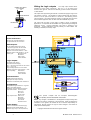
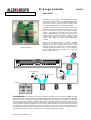
INTERNAL PL-8 CIRCUIT
(1 OF 4 SHOWN)
+5V
470R
SERIES RESISTOR
1 2 3 4 G G G
LED INDICATOR
TYPICALLY 6mA
Wiring the logic outputs
The 7way output terminal block
provides four logic output connections. Pins 5 to 7 ‘G’ are used as the
common return ground. One wire can feed this ground to a bank of indicators
or other devices.
The output works by switching the internal +5V reference supply through a 470
ohm resistor to the pin. This presents a positive voltage when the output is
turned on, and an open circuit when it is turned off. The switching is done
using a transistor. The resistor limits the current to a maximum 10mA to ensure
the connected equipment does not draw more than the PL-8 can provide.
The output may be used in many ways to satisfy a range of interfacing
applications. It is important that the installer has a good working knowledge of
interfacing circuits. Incorrect application may result in damage to the
equipment. Typical applications include powering an LED indicator and
switching solid state (low current) relays.
Specification
SWITCH
In/Out Connectors:
SWITCH
Phoenix 7way screw terminal blocks
For permanent bare wire connection
SWITCH
SWITCH
Switch Inputs:
4x opto-isolated switch closure inputs
+5V DC through series 1k5 ohm resistor
Switch closure connects pin to ground
Maximum current when switched = 1.2mA
Maximum switch+cable resistance = 1k ohm
Switch types:
Momentary action
Microswitch
Relay contact
Custom interface
PL-8
Communication:
RS485 based PL-Anet serial port
RJ45 input and output connectors
Maximium 15x addresses per PL-Anet branch
Configuration:
iDR System Manager software V3.1 or greater
Refer to the software Help file
Separately configure switches and outputs
Input switch function: Volume up/down
Mute on/off
Patch recall
Monitor select
Logic output function: Static on/off
Mute status
Soft switched
Patch recalls
Scheduled events
Power Supply:
Internal +5V DC from PL-Anet 20V supply
Minimum PL-Anet voltage at PL-8 = 11V
Maximum logic output = 40mA (all shorted)
4
GG
INPUTS
1K5
OPTO-ISOLATED SWITCH INPUTS
PL-Anet OUT
Logic Outputs:
4x transistor logic outputs
Uses internal PL-Anet supply
ON = +5V DC through series 470 ohm resistor
OFF = open circuit
Output voltage depends on current drawn
Maximum current per output (shorted) = 10mA
Output capability:
LED indicator
Solid state relay
Custom interface
1 2 3 4 G
PL-Anet IN
CONTROL
CHAIN
To next PL-Anet device
or terminator
+20V
From iDR or previous
PL-Anet device
+5V
LOGIC OUTPUTS
470R SERIES RESISTOR
OUTPUTS
1 2 3 4 G
GG
LED INDICATOR
LAMPS
MOTORS
EQUIPMENT
SOLID STATE +
RELAYS
-
DEVICE
This product complies with the European
Compatibility directives 89/336/EEC & 92/31/EEC.
Electromagnetic
NOTE: Any changes or modifications to the equipment not approved by Allen
& Heath could void the compliance of the equipment. Whilst we believe the
information in this guide to be reliable we do not assume responsibility for
inaccuracies. We also reserve the right to make changes in the interest of
further product development.
Copyright© 2005 Allen & Heath Ltd. All rights reserved.
PL-8 User Guide AP5270 issue 3