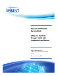
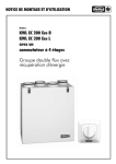
1
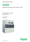
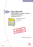
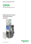
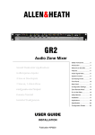
PL-12 Wall Plate
AP6506
User Guide
The PL-12 is an ‘intelligent’ remote controller for use with the Allen & Heath
GR2 audio zone mixer. It provides the non-technical operator with local control
of the music source selection and/or audio level. Up to two controllers may be
connected, just one, one for each zone, or a single unit to simultaneously
control both zones. A menu of setup options allows the installer to configure
its function to match the specific requirements of each application. Additional
switches may be wired for room combining situations and to disable the
controller when the settings should not be changed. The optional PL-5 hand
held infra-red remote controller adds wireless control, and additional features
including the store and recall of up to 4 source/level presets. The PL-12 can
be mounted into a single unit wall box using the standard face plate provided,
or furniture mounted using the cutting template details given here. It interfaces
with the GR2 using standard CAT5 cables. The second controller daisy chains
with the first for convenient single run cabling. Space is provided on the panel
for custom labelling.
PL-12
ALLEN&HEATH
GR2
PL-5
PL-12 Controls
LEVEL
INDICATOR
SOURCE
INDICATOR
LEVEL
CONTROL
SOURCE -
INFRA-RED
SENSOR
SOURCE +
•
Source select Scroll up/down through the available music sources.
•
Source indicators Light green to show the selected source, red for mute.
•
Rotary level control Adjusts audio level in 32 steps from off to on.
•
Level indicator 8 LED bar to display the level.
•
Infra-red sensor Detects the optional PL-5 hand held controller.
•
Label space Recessed areas for custom labelling.
PL-5 Controls
LEVEL
UP/DOWN
1
SOURCE
SELECT
2
SOURCE
SELECT
3
4
SOURCE
OFF
MUSIC
MUTE
5
(Option for the PL-12)
•
Source select keys Scroll up/down through the available music sources.
•
Source keys Direct selection of available music sources 1 to 4.
•
Source off key De-selects all sources.
•
Level keys Adjust the level up or down.
•
Music mute key Silences the selected source.
•
Preset keys Store and recall up to 4 presets of level and source selection.
ALLEN&HEATH
PL-12 Installation
PRESETS
DISABLE SWITCH OPTION
ZONE 2 FOLLOW ZONE 1 OPTION
FACE PLATE
FIXINGS
•
Face plate fixings Mount the module to the wall plate.
•
Zone select jumper Configures which zone to control.
•
Disable option Wire a switch to lock out the controls.
•
Zone 2 follow zone 1 option Wire a switch for control of both zones.
•
To GR2 RJ45 for CAT5 cable connection to GR2.
•
To next PL-12 RJ45 for CAT5 cable connection to second PL-12 if used.
PL-12 Setup Menu
TO NEXT PL-12
RJ45/CAT5
TO GR2
RJ45/CAT5
ZONE
SELECT JUMPER
PL-12 User Guide AP6506 issue 1
(Accessed and stored on the PL-12)
•
Zone 2 follow zone 1 mode Setting for one PL-12 to control both zones.
•
Sources to select Choice of combinations of none, 1234, 123, 234, 23.
•
Source off Add a source off position to the selection.
•
Power up default Choice of off, last settings, or one of 4 presets.
•
Preset enable Store and/or recall of 4 level/source presets using the PL-5.
1
TOP
Mounting to the face plate
A pre-cut brushed
aluminium wall plate is supplied according to territory, UK
(part number AA5029), EU (AA5250) or US (AA5030). A
suitable backing box for the UK plate can be ordered
(AA5220). The module fits into an ‘H’ shaped cutout in the
centre of the face plate. The module is held using the two
screws with plastic clamps provided (A). Unscrew these
from the module first. Should a custom mounting plate be
required, a template (in millimetres) is provided here.
Ensure that enough space is provided for the cables.
A
A
32
20
c
20
DIA 6
12
16
16
16
34
16
Safety ground Ensure that the supplied aluminium face plate (or any
custom metal plate) is correctly grounded to ensure operator safety. The plate
should be connected to a local safety ground. Use a ground wire or physical
contact with a grounded back box.
MAX CABLE LENGTH
2x PL-12
1x PL-12
60 m
50
40
30
20
10
1m
20
40
60
80
100
120 m
Connections Use standard one-to-one wired CAT5 / RJ45 cables. The
control of both zones is passed down a single CAT5 cable. Connect the GR2
ZONE REMOTE port to the first PL-12 TO GR2 port (CN1). If two remotes are
used, connect the first LINK port to the second TO GR2 port (CN2). Do not
connect more than two remotes. Note the maximum cable length from the
diagram shown here. Use unbooted plugs to ensure the cables can fit into the
backing box. Allow enough service loop for module removal.
Assigning which zone to control Set the module jumper plug to
the Z1 (zone 1) or Z2 (zone 2) position. Do this while the remote power is
turned off. If two remotes are used they must not be set to control the same
zone. The first remote in the chain may be set to either Z1 or Z2.
CN2
Z1 Z2
CN1
LINK
TO GR2
Wiring a disable switch (option) Solder pads are provide for
connecting an external switch to disable the remote and protect the settings,
for example when the room should not be used. Such a switch could be
located near the GR2 or in the manager’s office. Each remote can have its own
disable switch. When disabled, the 4 source indicators light red.
Wiring a zone 2 follow zone 1 switch (option)
DISABLE REMOTE
1 2 3 4
Z2 FOLLOW Z1
Solder
pads are provided for connecting an external switch to change the operating
mode so that the zone 1 remote controls both zone 1 and zone 2. This is
useful when two rooms are used independently or combined into one on some
occasions by opening a divider screen. When combined, the zone 1 remote
controls the speakers simultaneously in both rooms. The switch must be
connected to the zone 1 remote. Connect the wires to a manually operated
switch or a micro-switch that changes state when the divider screen is opened
or closed. When the screen is open the switch contacts should be closed.
Note that setup menu option 1 may be used instead of the switch to
permanently set this mode if the one remote always controls both zones.
Option 8 determines whether follow affects the level and source, or source
only. If source only, the level can be independently set for each zone using
both remotes. If level and source, the zone 2 remote is fully disabled.
Configuring the GR2
The GR2 can be configured to operate in many
different ways. Check that its front panel DIP switches are correctly set for your
application. Make sure the remote enable switches MNOP are set according to
which zones you want the PL-12 units to control, and whether they should
work with just the level or level and source selection. Refer to user guide
AP6320. Also decide which music sources to include in the selection.
remote enable
M N O P
on
Z1 source
Z1 level
Z2 source
Z2 level
Note: On power up, the PL-12
firmware version number is displayed
briefly on one of the 8 level indicators.
2
PL-12 menu options A setup menu is available to configure the
remote to match your application. For example, you may wish the source
selection to scroll between 2, 3 and 4 if you have configured the GR2 for 4
music sources with music 1 a jukebox priority source that should not be
selected on the wall plate. Refer to the menu table later in this guide on the
options available.
Configuring the PL-12 Default setting is to select between music
sources 1, 2 and 3, to power up with the last settings, the PL-5 preset store and
recall functions disabled, and the zone 2 follow zone 1 function affecting both
source and level. A good starting point is to reset the remote before
configuration. Refer to the reset and option menu instructions later in this
guide. Use the CONFIGURATION SHEET in the GR2 user guide to log your
system and option settings (can be downloaded from www.allen-heath.com).
PL-12 User Guide AP6506 issue 1
Using one PL-12 remote to control zone 1:
ZONE 1
remote enable
M N O P
Z1 Z2
on
Z2 source
Z2 level
Z1 source
Z1 level
SET SWITCHES FOR ZONE 1
REMOTE CONTROL
Using one PL-12 remote to control zone 2:
ZONE 2
remote enable
M N O P
Z1 Z2
on
Z2 source
Z2 level
Z1 source
Z1 level
SET SWITCHES FOR ZONE 2
REMOTE CONTROL
Using two PL-12 remotes to independently control zone 1 and zone 2: (Note that they may be assigned in either order, 1-2 or 2-1)
Z1 Z2
ZONE 2
Z1 Z2
remote enable
M N O P
ZONE 1
on
Z2 source
Z2 level
Z1 source
Z1 level
SET SWITCHES FOR ZONES
1 & 2 REMOTE CONTROL
Using one PL-12 remote to control zone 1 and zone 2 simultaneously:
Z1 Z2
ZONE 1
+
ZONE 2
remote enable
M N O P
on
Set
menu
1 to ON
SETUP
OPTION 1option
= 'ON'
Z2 source
Z2 level
Z1 source
Z1 level
(ZONE 2 FOLLOW ZONE 1)
(zone 2 follow zone 1)
SET SWITCHES FOR ZONES
1 & 2 REMOTE CONTROL
Using two PL-12 remotes with room combining:
Z2 FOLLOW Z1
(ROOM COMBINER MICROSWITCH)
1 2 3 4
ZONE 2
ZONE 1
remote enable
M N O P
on
Z1 Z2
Z1 Z2
Z1 source
Z1 level
ROOM
DIVIDER
Z2 source
Z2 level
SET SWITCHES FOR ZONES
1 & 2 REMOTE CONTROL
Wire the room divider switch to the zone 1 remote.
1 2 3 4
Check that menu option 1 is set to OFF on both remotes.
ZONE 1
ZONE 2
Check that menu option 8 is set the same on both remotes.
Option 8 = source+level + zone 1 remote controls both, zone 2 turns off.
Z1 Z2
Option 8 = source only = zone 1 controls both sources, separate level.
Z1 Z2
ROOM
DIVIDER
Wiring disable switches to turn off the PL-12 local control:
DISABLE ZONE 2 WALL PLATE
1 2 3 4
DISABLE ZONE 1 WALL PLATE
1 2 3 4
ZONE 2
PL-12 User Guide AP6506 issue 1
ZONE 1
3
1
2
3
4
5
6
7
8
1
1 = FLASHES RED
2
3 = FLASHES GREEN
3
4
2 = COUNTS DOWN
HOLD
+
POWER UP
Resetting the PL-12 To reset the controller to the default settings
shown in the table below, press and hold the V (down) and U (up) keys while
powering up the system. Do this by switching on the GR2 or by plugging in
the PL-12 CAT5 cable TO GR2 connection while the GR2 is on. Keep the key
pressed while the 4 source indicators flash red, the 8 level indicators count
down one at a time, and finally the source indicators flash green to confirm the
reset. Releasing the keys before the sequence finishes cancels the reset.
PL-12 option menu
1
2
3
4
5
6
7
8
1
PARAMETER
DISPLAY
2
3
4
OPTION
NUMBER
DISPLAY
OPTION
SELECT
CHANGE
PARAMETER
ENTER
SETUP
Access using the front panel keys.
Enter and exit setup Press and hold the V(down) key for 4 seconds to enter
setup mode. The 4 source indicators light orange until an option is selected by
turning the rotary. Keep the V key held down while changing the settings.
To save the settings and return to normal operating mode release the key.
Option select Turn the rotary control to scroll through the 8 available options.
The current option number is displayed on the LED indicator bar above.
Parameter display The current setting for the selected option is displayed on
the 4 LED indicators.
Change parameter While holding the V key, tap the U (up) key to cycle
through the available parameters. These are detailed in the table below.
OPTION
LED 1
Off, On
1
Zone 2 follow Zone 1
2
Sources to select
123, 234, 23, 0, 1234
3
Source off position
Off, On
4
Power up default
Last, Off, Preset
5
Power up preset
6
LED 2
LED 3
LED 4
Red = Off
Gn = On
music 1
COMMENT
Can only be set on the zone 1 controller
music 2
music 3
music 4 Cycle through the available options
Red = Off
Gn = On
Adds a 'no source' selection
Last
Off
Preset
1, 2, 3, 4
preset 1
preset 2
preset 3
PL-5 preset recall
Off, On
Red = Off
Gn = On
Enables preset recall from the PL-5 IR controller
7
PL-5 preset store
Off, On
Red = Off
Gn = On
Enables preset store from the PL-5 IR controller
8
Follow mode
Source, Source+Level
Source
The source selection and level on power up
preset 4 Which preset shall be recalled on power up (if set in option 4)
Level
Which zone 2 parameter follows the zone 1 controller
Must be set the same on both zone 1 and 2 controllers
Reset defaults shown in bold above
Working with presets
The optional PL-5 infra-red hand-held
controller adds the presets function. Up to 4 level and source selection
combinations may be stored in the PL-12 memory. This is convenient for quick
recall of settings for regular events. The installer can store these during
installation, then use menu option 7 to disable store to prevent them being
overwritten by the operator. To disable preset recall use menu option 6.
PRESET
KEYS
ALLEN&HEATH
To store a preset Select the required source and level. Hold down the
required PL-5 preset key for 4 seconds. The PL-12 source indicators all flash
green to confirm the store.
To recall a preset Briefly press and release the required PL-5 preset key.
Important: Observe the local standards which
may apply to the installation. To ensure operator
safety ensure that exposed metal plates are correctly
bonded to ground. Do not install the equipment
where it is subject to moisture, heat or vibration.
Warning: To avoid damage, connect the PL-12
to the Allen & Heath GR2 only. This product is not
compatible with the Allen & Heath PL-Anet system.
To avoid damage to the equipment, make sure
all wiring is inspected and continuity tested before
powering up the system.
4
NOTE: Do not install the PL-12 in a position subject
to bright sunlight as this may reduce the effectiveness
of the IR signal. Note that if you have two PL-12 in
one room they may both pick up the signal from one
IR controller. This may or may not be desired.
This product complies with the
Electromagnetic
Compatibility
89/336/EEC & 92/31/EEC.
European
directives
NOTE: Any changes or modifications to the equipment not
approved by Allen & Heath could void the compliance of the
equipment. Whilst we believe the information in this guide to
be reliable we do not assume responsibility for inaccuracies.
We also reserve the right to make changes in the interest of
further product development. Copyright© 2005 Allen & Heath
Ltd. All rights reserved.
PL-12 User Guide AP6506 issue 1