1
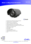
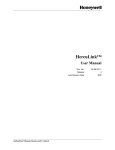
Quick Start Guide
For GVX9000 AF Drives
June 2006
New Information
5011646300
00GQ
MN04000002E
June 2006
Step 1 — Wiring
Hazardous High Voltage
HIGH VOLTAGE!
Motor control equipment and electronic controllers are connected to
hazardous line voltages. When servicing drives and electronic
controllers, there may be exposed components with housings or
protrusions at or above line potential. Extreme care should be taken to
protect against shock.
For the best results with the GVX9000 inverter, carefully read the
manual and all of the warning labels attached to the inverter before
installing and operating it, and follow the instructions exactly.
Wire Type: 75ºC Copper Only
Catalog
Number
Voltage
Horsepower
Max.
Current
in Amps
(Input/Output)
Wire Gauge
in AWG
(mm2)
14 (2.1)
12 (3.3)
10 (5.3)
10 (5.3)
Torque Rating
in kgf-cm
[in-lb]
GVX001A1-2
GVX002A1-2
GVX003A1-2
GVX005A1-2
240V, 1 hp
240V, 2 hp
240V, 3 hp
240V, 5 hp
11.9 / 5
15.3 / 7
22.0 / 11
20.6 / 17
GVX007A1-2
GVX010A1-2
GVX015A1-2
GVX020A1-2
240V, 7-1/2 hp
240V, 10 hp
240V, 15 hp
240V, 20 hp
26 / 25
34 / 33
50 / 49
60 / 65
GVX025A1-2
GVX030A1-2
GVX040A1-2
GVX050A1-2
240V, 25 hp
240V, 30 hp
240V, 40 hp
240V, 50 hp
GVX001A1-4
GVX002A1-4
GVX003A1-4
GVX005A1-4
480V, 1 hp
480V, 2 hp
480V, 3 hp
480V, 5 hp
3.2 / 2.7
4.3 / 4.2
5.9 / 5.5
11.2 / 8.5
18 (0.8)
18 (0.8)
18 (0.8)
18 (0.8)
18 [15.6]
18 [15.6]
18 [15.6]
18 [15.6]
GVX007A1-4
GVX010A1-4
GVX015A1-4
GVX020A1-4
480V, 7-1/2 hp
480V, 10 hp
480V, 15 hp
480V, 20 hp
19 / 18
25 / 24
33 / 32
46 / 38
10 (5.3)
8 (8.4)
8 (8.4)
6 (13.3)
30 [26.0]
30 [26.0]
30 [26.0]
30 [26.0] Use Terminal
GVX025A1-4
GVX030A1-4
GVX040A1-4
GVX050A1-4
480V, 25 hp
480V, 30 hp
480V, 40 hp
480V, 50 hp
56 / 45
70 / 60
75 / 73
95 / 91
4 (21.2)
3 (26.7)
3 (26.7)
2 (33.6)
30 [26.0] Use Terminal
30 [26.0] Use Terminal
57 [49.5]
57 [49.5]
GVX060A1-4
GVX075A1-4
GVX100A1-4
480V, 60 hp
480V, 75 hp
480V, 100 hp
110 / 110
150 / 150
180 / 180
8 (8.4)
8 (8.4)
6 (13.3)
4 (21.2)
75 / 75
90 / 90
110 / 120
142 / 145
3 (26.7)
2 (33.6)
1/0 (53.5)
3/0 (85)
1/0 (53.5)
3/0 (85)
4/0 (107.2)
18 [15.6]
18 [15.6]
18 [15.6]
18 [15.6]
30 [26.0]
30 [26.0]
30 [26.0] Use Terminal
30 [26.0] Use Terminal
30 [26.0] Use Terminal
30 [26.0] Use Terminal
200 [173.6]
200 [173.6]
200 [173.6]
200 [173.6]
200 [173.6]
Basic Wiring Diagram
Users must connect wiring according to the following circuit diagram.
MN04000002E
1
June 2006
Control Terminal Wiring (Factory Settings)
Sink Mode
+24V +10V
RUN/STOP
D1
FWD/REV
D2
AI2
4~20mA
Multi-Step 1
D3
AI3
Multi-Step 2
D4
AO+
–10V~+10V
Full Scale Voltmeter 0 to 10V DC,
Factory Setting: Analog Frequency
Multi-Step 3
D5
A–
Multi-Step 4
D6
DO1
External Reset
D7
DO2
DOC
Digital Output Factory Setting: Warning
Digital Output Factory Setting:
Frequency Setting Indication
Digital Output Common
RB2
Factory Setting Fault Indication
RB1
NO Relay Output
RA3
NC Relay Output
External Fault
D8
Parameter Disable
D9
Parameter Disable
D10
Digital Frequency Output
Digital Signal Common
DPO
AI1
COM RA2
RA1
Factory Setting Drive Running
NO Relay Output
Source Mode
+24V +10V
RUN/STOP
D1
REV/FWD
D2
AI2
4~20mA
Multi-Step 1
D3
AI3
Multi-Step 2
D4
AO+
–10V~+10V
Full Scale Voltmeter 0 to 10V DC,
Factory Setting: Analog Frequency
Multi-Step 3
D5
A–
Multi-Step 4
D6
DO1
External Reset
D7
DO2
DOC
Digital Output Factory Setting: Warning
Digital Output Factory Setting:
Frequency Setting Indication
Digital Output Common
RB2
Factory Setting Fault Indication
RB1
NO Relay Output
RA3
NC Relay Output
External Fault
D8
Parameter Disable
D9
Parameter Disable
D10
Digital Frequency Output
Digital Signal Common
DPO
AI1
COM RA2
RA1
Factory Setting Drive Running
NO Relay Output
Terminal Symbols
Terminal
Symbols
RA1 - RA3
Terminal Name
Digital Output Relay 1 (FORM C)
Remarks
Refer to 40.03, 40.04
RB1 - RB2
Digital Output Relay 2 (FORM A)
D01 - DOC
D02 - DOC
Digital Photocouple Outputs
Refer to 40.05, 40.06
RJ12 Port
Serial Communication port
RS-485 serial communication
interface
+10V -A-
10V power supply
AI1 -A-
Analog voltage input 1
MN04000002E
0 – 10V input
2
June 2006
Terminal Symbols (Continued)
Terminal
Symbols
Terminal Name
Remarks
AI2 -A-
Analog voltage input 2
4 – 20 mA input
AI3 -A-
Analog voltage input 3
-10 to 10V input
A0+ -A-
Analog voltage output
0 to 10V output
D1 - COM
to
D10 - COM
Digital Inputs 1 – 10
Refer to 30.20 – 30.28
DPO - COM
Digital Pulse Output
Refer to 40.08
+24 - COM
24V Power Supply
Used for Source mode
Note: Use twisted-shielded, twisted-pair or shielded-lead wires for the control
signal wiring. It is recommended to run all signal wiring in a separate steel
conduit. The shield wire should only be connected at the drive. Do not connect
shield wire on both ends.
HIGH VOLTAGE!
Wiring work shall be carried out only by qualified personnel.
Otherwise, there is a danger of electric shock or fire.
Step 2 — Keypad Operation
Digital Keypad Operation
The digital keypad includes the display panel and the keypad. The display panel
provides the parameter display and shows the operation status of the AC drive.
The keypad provides programming and control interface.
LOC REM Key
Switches the Control
from Local Control Source
to Remote Control Source
FORWARD REVERSE Key
LCD Display
Indicates Motor and
Drive Parameter
RUN STOP FWD REV
FWD
REV
LOC
LED Indicators
Lamp Lights During Run,
Stop, Fwd, Rev, Loc Operations
START Key
Start Command
LOC
REM
STOP/RESET Key
Stop Command and Reset
the Drive After a Fault Occurs
Up, Down and
Right/Left Keys
Scrolls Display,
Enter/Exit Parameter Mode,
Change Parameter Settings
ENTER Key
Used in Parameter Mode
to Enter and Change Values
Keypad Operators
START
This button operates as Start button for normal operation
• Motor START from the panel; active control place has to be
selected at “Panel”
ENTER
This button in the parameter edit mode is used to enter the
programming mode and enter the parameter selection.
• used for parameter edit confirmation, acceptance (confirmation)
of the edited parameter value with exit from parameter edit mode
MN04000002E
3
June 2006
Keypad Operators (Continued)
STOP / RESET
This button has two integrated operations. The button operates as
Stop button for normal operation. In the parameter edit mode it is
used to cancel previous action and back-up one step, and in fault
mode it is used to reset the fault.
STOP
• motor STOP from the panel; active control place has to be
selected at “Panel”
RESET
• used to reset an Active Fault on the drive and shown in the
display
LOC
REM
FWD
REV
This button switches the Control Location from the Local Source to
the Remote Source.
This button changes the direction of the motor connected to the
GVX9000 drive.
LEFT Arrow
• navigation button, movement to left
• in display mode, enter parameter group mode
• in parameter edit mode, exits mode, backs up one step
• cancels edited parameter (exit from a parameter edit mode)
RIGHT Arrow
• navigation button, movement to right
• enter parameter group mode
• enter parameter mode from group mode
• Changes the cursor location when entering data into a parameter
UP and DOWN Arrows
• move either up or down the group list in order to select the
desired group menu.
• move either up or down the parameter list in order to select the
desired parameter in the group.
• increasing/decreasing of reference value on the keyboard (when
selected).
Step 3 — Parameter Navigation
This page and Page 5 contain the descriptions of the GVX9000 parameters.
Parameters are addressed and changed via the keypad for the GVX9000. For
more information on keypad operation, see Keypad Operation located in Chapter
2 of the manual.
Viewing and Changing Parameter Settings
40
Display
Hz
AMPS
USER
MN04000002E
30
20
Page Groups
Parameters are grouped in a page
arrangement. Each page will contain a
list of the parameters associated with
that group. Move into the page groups
from the display menu by using the right
arrow key.
4
June 2006
Parameter Groups
Select the desired parameter group by
using the up and down keys. Once the
parameter group is located, use the right
arrow key to enter the group. Use the up
and down keys to scroll the parameters
on that page.
40
30
40.01
40.02
40.03
40.04
40.05
20
Group 30: Inputs
30.01 - 30.50
RUN STOP FWD REV
A1 Max Volt In
30.01 = 10.00Vdc
LOC
RUN STOP FWD REV
A1 Max Volt In
30.01 = 10.00Vdc
RUN STOP FWD REV
LOC
A1 Min Volt In
30.02 = 0.00Vdc
LOC
RUN STOP FWD REV
This digit flashes. The
right arrow key
changes the flashing
digit location.
A1 Max Volt In
30.01 = 10.00Vdc
RUN STOP FWD REV
Value Accepted
RUN STOP FWD REV
LOC
LOC
Invalid Data
LOC
Successful Parameter Change
RUN STOP FWD REV
LOC
Unsuccessful Parameter Change
Parameter Setting
Once the parameter has been located,
use the right arrow key to view the
parameter setting.
Scrolling Parameters
Once in the parameter setting, use the up
and down keys to scroll through the
parameters.
Programming Mode
Use the ENTER key to enter the
programming mode. The displayed
parameter will flash indicating the
parameter can be changed.
Parameter Changes
Use the up and down keys to change the
parameter setting. Press ENTER to enter
the new parameter setting.
If the parameter change is successful, the keypad will display the Value Accepted
message and return to the parameter number display. If the parameter change is
unsuccessful the keypad will display an Invalid Data message, the parameter will
not be changed, and the parameter number will again be displayed.
Note: Some parameters cannot be changed while the unit is the RUN/START mode.
To exit the programming mode, press the left arrow key to return to the display mode.
Step 4 — Parameter Groups & Default Values
Parameter Groups
The parameters are grouped according to the following descriptions:
20 — Easy Mode Settings . . . . . . . . . . . . . . . . . . . . . . . . . . . . . . . . . . . . . . . . . . 6
30 — Inputs . . . . . . . . . . . . . . . . . . . . . . . . . . . . . . . . . . . . . . . . . . . . . . . . . . . . . . 6
40 — Outputs . . . . . . . . . . . . . . . . . . . . . . . . . . . . . . . . . . . . . . . . . . . . . . . . . . . . 8
50 — AC Drive Control . . . . . . . . . . . . . . . . . . . . . . . . . . . . . . . . . . . . . . . . . . . . . 9
60 — Motor Control . . . . . . . . . . . . . . . . . . . . . . . . . . . . . . . . . . . . . . . . . . . . . . . 13
70 — Protective Functions . . . . . . . . . . . . . . . . . . . . . . . . . . . . . . . . . . . . . . . . . . 14
80 — Keypad / Display . . . . . . . . . . . . . . . . . . . . . . . . . . . . . . . . . . . . . . . . . . . . . 15
90 — Communication . . . . . . . . . . . . . . . . . . . . . . . . . . . . . . . . . . . . . . . . . . . . . . 17
MN04000002E
5
June 2006
GVX9000 Parameter Listings
20 — Easy Mode Settings
Modbus
Groups
20.01
Parameter
Description
Easy Mode Selection
Range
00 – 09
Default
User
Settings
00
00
Factory Settings
01
02
Basic V/F Curve
PID Control
03
Preset Speeds
04
Local/Remote
05
06
07
08
09
Hand Off Auto (HOA)
Variable Torque (Pump/Fan)
Spindle Motor
Analog Speed Command
Closed Loop Vector Control
30 — Inputs
Modbus
Groups
0100H
30.01
0101H
30.02
0102H
30.03
0103H
30.04
0104H
30.05
0105H
30.06
0106H
30.07
0107H
30.08
0108H
30.09
0109H
30.10
Parameter
Description
A1 Maximum Input
Voltage (0 – 10V)
A1 Minimum Input
Voltage (0 – 10V)
A1 Maximum Output
Frequency
A1 Minimum Output
Frequency
A1 Reverse Option
A2 Maximum Input
Current (0 – 20 mA)
A2 Minimum Input
Current (0 – 20 mA)
A2 Maximum Output
Frequency
A2 Minimum Output
Frequency
A2 Reverse Option
010AH
30.11
010BH
30.12
010CH
30.13
010DH
30.14
010EH
30.15
A3 Reverse Option
010FH
0110H
0111H
0112H
30.16
30.17
30.18
30.19
A1 Response Time
A2 Response Time
A3 Response Time
Analog Input Frequency
Resolution
MN04000002E
A3 Maximum Input
Voltage (-10 – 10V)
A3 Minimum Input
Voltage (-10 – 10V)
A3 Maximum Output
Frequency
A3 Minimum Output
Frequency
Range
Default
0.00 to 10.00V
10.00
0.00 to 10.00V
0.00
-400.0 to 400.0 Hz
60.00
-400.0 to 400.0 Hz
0.0
00
01
00
Negative input = 30.04
Negative input = Reverse
direction
02
Negative input = Frequency
command only, no Direction
0.00 to 20.00 mA
20.00 mA
0.00 to 20.00 mA
4.00 mA
-400.0 to 400.0 Hz
60.00
-400.0 to 400.0 Hz
0.0
00
01
Negative input = 30.09
Negative input = Reverse
direction
02
Negative input = Frequency
command only, no Direction
-10.00 to 10.00V
00
-10.00 to 10.00V
-10.00V
-400.0 to 400.0 Hz
60.00
10.00V
-400.0 to 400.0 Hz
0.0
00
01
01
Negative input = 30.14
Negative input = Reverse
direction
02
Negative input = Frequency
command only, no Direction
0.00 to 10.00 sec.
0.00 to 10.00 sec.
0.00 to 10.00 sec.
00 0.01 Hz
01
User
Settings
0.05 sec.
0.05 sec.
0.05 sec.
01
0.1 Hz
6
June 2006
30 — Inputs (Continued)
Modbus
0113H
Groups
30.20
Parameter
Description
Digital Input Terminals
D1, D2
Range
01
2-wire Operation Mode 1
D1: FWD / STOP
D2: REV / STOP
02
2-wire Operation Mode 2
D1: RUN / STOP
D2: REV / FWD
3-wire Operation Mode
D1: RUN
D2: REV / FWD
D3: STOP
03
0114H
30.21
Digital Input Terminal
(D3)
0115H
30.22
0116H
30.23
0117H
30.24
0118H
30.25
Digital Input Terminal
(D4)
Digital Input Terminal
(D5)
Digital Input Terminal
(D6)
Digital Input Terminal
(D7)
MN04000002E
Default
User
Settings
02
00
01
02
03
04
05
06
07
08
09
10
Parameter Disable
05
External Fault (NO) EF
External Fault (NC) EF
External Reset (NO)
External Reset (NC)
Preset Speed Switch 1
Preset Speed Switch 2
Preset Speed Switch 3
Preset Speed Switch 4
Jog
2nd Acceleration/Deceleration
time selection
11
3rd Acceleration/Deceleration
time selection
12
Control Location Hand — HOA
13
Control Location Auto — HOA
14
Control Location Remote —
Local/Remote (close for
remote)
15
Increase Master Frequency
16
Decrease Master Frequency
17
Forward / Reverse
18
Parameter Lock
19
Acceleration / Deceleration
Inhibit
20
Run Enable
21
PAUSE (NO)
22
PAUSE (NC)
23
PID Disable
24
Counter input
25
Counter reset
26
Auxiliary Motor 1 Output
Failure
27
Auxiliary Motor 2 Output
Failure
28
Auxiliary Motor 3 Output
Failure
29
Output Shut Off (NO)
30
Output Shut Off (NC)
31
Auto/Linear Acceleration/
Deceleration
32
Proximity sensor input (index
function)
33
Forced Stop (NO)
34
Forced Stop (NC)
See Parameter 30.21
06
See Parameter 30.21
07
See Parameter 30.21
08
See Parameter 30.21
03
7
June 2006
30 — Inputs (Continued)
Modbus
Groups
0119H
30.26
011AH
30.27
011BH
011CH
Parameter
Description
Range
Default
Digital Input Terminal
(D8)
Digital Input Terminal
(D9)
See Parameter 30.21
01
See Parameter 30.21
00
30.28
Digital Input Terminal
(D10)
See Parameter 30.21
00
30.29
Final Count Value
00 to 65000
00
00 to 65000
011DH
30.30
Intermediate Count
Value
011EH
011FH
0120H
0121H
0122H
0123H
0124H
0125H
0126H
0127H
0128H
0129H
012AH
012BH
012CH
012DH
30.31
30.32
30.33
30.34
30.35
30.36
30.37
30.38
30.39
30.40
30.41
30.42
30.43
30.44
30.45
30.46
Preset Speed 1
Preset Speed 2
Preset Speed 3
Preset Speed 4
Preset Speed 5
Preset Speed 6
Preset Speed 7
Preset Speed 8
Preset Speed 9
Preset Speed 10
Preset Speed 11
Preset Speed 12
Preset Speed 13
Preset Speed 14
Preset Speed 15
Display Frequency (Hz)
or Percent (%)
012EH
30.47
012FH
30.48
0130H
30.49
0131H
30.50
User
Settings
00
0.00 to 400.00 Hz
0.00 to 400.00 Hz
0.00 to 400.00 Hz
0.00 to 400.00 Hz
0.00 to 400.00 Hz
0.00 to 400.00 Hz
0.00 to 400.00 Hz
0.00 to 400.00 Hz
0.00 to 400.00 Hz
0.00 to 400.00 Hz
0.00 to 400.00 Hz
0.00 to 400.00 Hz
0.00 to 400.00 Hz
0.00 to 400.00 Hz
0.00 to 400.00 Hz
00
Frequency (Hz)
01
Percent (%)
02
User Definition (0.001 – max.
unit) Unit set by 30.47
User Definition for 30.46 0.001 to 10.000
Option 2
Gear Ratio for Simple
4 to 1000
Index Function
Index Angle for Simple
0.0 to 360.0 Deg
Index Function
Deceleration Time for
0.0 to 100.0
Simple Index Function
0.00 Hz
0.00 Hz
0.00 Hz
0.00 Hz
0.00 Hz
0.00 Hz
0.00 Hz
0.00 Hz
0.00 Hz
0.00 Hz
0.00 Hz
0.00 Hz
0.00 Hz
0.00 Hz
0.00 Hz
00
1.000
200
180
0.0
40 — Outputs
Modbus
0200H
Groups
40.01
Parameter
Description
Analog Output
Reference
Range
00
Default
Output Frequency (0 to
Maximum Output Frequency)
Output Current (0 to 250% of
the rated AC drive current)
02
Output Voltage (0 to 50.16)
03
Command Frequency (0 to
50.14)
04
Output Motor Speed (vector
mode)
05
Load Power Factor
(cos90º to 0º)
0 to 200%
00 to 33
100
02
00 to 33
03
User
Settings
00
01
0201H
0202H
40.02
40.03
0203H
40.04
0204H
40.05
0205H
40.06
MN04000002E
Analog Output Gain
Digital Output Terminal
Relay A (RA1, RA2, RA3)
Digital Output Terminal
Relay B (RB1, RB2)
Digital Output Terminal
DO1
Digital Output Terminal
DO2
00 to 33
04
00
01
02
Not Used
Ready
Inverter output is active
05
03
Inverter Fault
8
June 2006
40 — Outputs (Continued)
Modbus
0205H
Groups
40.06
Parameter
Description
Digital Output Terminal
DO2
Range
04
Warning (for detail, refer to the
GVX9000 AF Drives User
Manual, Chapter 7.)
05
At speed
06
Zero Speed (Fout < Fmin during
Run)
07
Desired Frequency Attained 1
(40.07)
Below Frequency Attained 1
(40.07)
PID supervision
Over voltage supervision
Over heat supervision
Over current stall supervision
Over voltage stall supervision
Final Count value attained
Midpoint Count value attained
Reverse direction notification
(command)
17
Under current detection
18
Over torque detection
19
Pause enabled
20
External control
21
Auxiliary Motor 1
22
Auxiliary Motor 2
23
Auxiliary Motor 3
24
Fout = 0.0 Hz (any state, STOP
or RUN)
25
E-Stop
26
Above Frequency Attained 2
(40.09)
27
Soft Braking Signal
28
Fout = 0.0 Hz (during a RUN
command)
29
Fout > Fmin
30
PG Error
31
Low Voltage indication (User
Defined)
32
Inverter RUN command state
33
Brake ON/ Brake OFF (40.10,
40.11)
Frequency Attained 1
0.00 to 400.00 Hz
Digital Output Multiplier 01 to 20
Frequency Attained 2
0.00 to 400.00 Hz
Brake Release
0.0 to 400.0 Hz
Frequency (Brake OFF)
Brake Engage
0.0 to 400.0 Hz
Frequency (Brake ON)
EF Displayed at
00
Disabled
Midpoint Count
01
Display EF when midpoint
count is reached
Default
User
Settings
05
08
09
10
11
12
13
14
15
16
0206H
0207H
0208H
0209H
40.07
40.08
40.09
40.10
020AH
40.11
020BH
40.12
0.00
00
0.00
0.0
0.0
00
50 — AC Drive Control
Modbus
0300H
Groups
50.01
Parameter
Description
Range
Source of LOCAL/HAND 00
Frequency
01
Master Frequency determined
by digital keypad on the drive.
Master Frequency determined
by 0 – 10V on terminal AI1.
Master Frequency determined
by 4 – 20 mA on terminal AI2.
Master Frequency determined
by -10 – 10V on terminal AI3.
02
03
MN04000002E
9
Default
User
Settings
00
June 2006
50 — AC Drive Control (Continued)
Modbus
0300H
0301H
Groups
50.01
50.02
Parameter
Description
Range
Source of LOCAL/HAND 04
Frequency
Master Frequency determined
by RS-485 (Frequency
retained)
05
Master Frequency determined
by RS-485 (Frequency not
retained)
Master Frequency determined
by digital keypad on the drive.
Master Frequency determined
by 0 – 10V on terminal AI1.
Master Frequency determined
by 4 – 20 mA on terminal AI2.
Master Frequency determined
by -10 – 10V on terminal AI3.
Master Frequency determined
by RS-485 (Frequency
retained)
Master Frequency determined
by RS-485 (Frequency not
retained)
Operating commands
determined by the Digital
Keypad.
Operating commands
determined by the External
Control Terminals. Keypad
STOP key is enabled.
Operating commands
determined by the External
Control Terminals. Keypad
STOP key is not enabled.
Operating commands
determined by the RS-485
communication interface.
Keypad STOP key is enabled.
Operating commands
determined by the RS-485
communication interface.
Keypad STOP key is not
enabled.
Operating commands
determined by the Digital
Keypad.
Operating commands
determined by the External
Control Terminals. Keypad
STOP key is enabled.
Operating commands
determined by the External
Control Terminals. Keypad
STOP key is not enabled.
Operating commands
determined by the RS-485
communication interface.
Keypad STOP key is enabled.
Operating commands
determined by the RS-485
communication interface.
Keypad STOP key is not
enabled.
Disable
Source of REMOTE/
AUTO Frequency
00
01
02
03
04
05
0302H
50.03
Source of LOCAL/HAND 00
Operation Command
01
02
0302H
50.03
Source of LOCAL/HAND 03
Operation Command
04
0303H
50.04
Source of REMOTE/
AUTO Operation
Command
00
01
02
03
04
0304H
50.05
0305H
0306H
50.06
50.07
0307H
50.08
MN04000002E
Dual Frequency Input
Mode
Trim Reference
Keypad Frequency
Setting
Stop Method
00
01
50.01 + 50.02
02
50.01 – 50.02
03
50.02 trims 50.01 (Reference)
0.00 to 100.00%
50.00 to 400.00 Hz
00
01
02
03
STOP = Ramp, EF = Coast
STOP = Coast, EF = Coast
STOP = Ramp, EF = Ramp
STOP = Coast, EF = Ramp
10
Default
User
Settings
00
01
00
00
01
00
0.00
60.00
00
June 2006
50 — AC Drive Control (Continued)
Modbus
Groups
Parameter
Description
Range
0308H
50.09
HOA Stop Method
0309H
50.10
4 – 20 mA Input Signal
Loss
00
01
030AH
50.11
0.1
030BH
50.12
4 – 20 mA Input Loss
Detection Time
UP/DOWN Key Speed
Decel to 0 Hz
Stop immediately and display
EF
02
Continue operation at last
known frequency
0.1 to 120.00 sec.
00
00
030CH
50.13
030DH
50.14
030EH
50.15
030FH
50.16
0310H
50.17
0311H
50.18
0312H
50.19
0313H
50.20
0314H
50.21
Control Mode
0315H
50.22
CT/VT Mode
0316H
50.23
Variable Torque Curve
Selection
0317H
50.24
0318H
Increment/Decrement
Rate of Frequency
Maximum Output
Frequency
Motor Nameplate
Frequency
Motor Nameplate
Voltage
00
Ramp
01
Coast
Default
Based on Accel/Decel time
(RUN state only)
01
Constant Speed (based on
50.13)
02
Based on Accel/Decel time,
frequency setpoint set to 0 Hz
upon a STOP command. (RUN
state only)
0.01 to 1.00 Hz/msec.
01
00
0.01
50 to 400.0 Hz
60.00
10.00 to 400.00 Hz
60.00
230V Series: 0.1 to 255.0V
460V Series: 0.1 to 510.0V
575V Series: 0.1 to 637.0V
0.00 to 400.00 Hz
230.0
460.0
575.0
1.50
230V Series: 0.1 to 255V
460V Series: 0.1 to 510V
575V Series: 0.1 to 637V
0.00 to 20.00 Hz
1.7
3.4
4.8
1.50
1.7
3.4
4.8
00
Acceleration Time 1
230V Series: 0.1 to 50V
460V Series: 0.1 to 100V
575V Series: 0.1 to 637V
00
V/F
01
V/F Closed Loop
02
Sensorless Vector (SV)
03
Vector Closed Loop (CLV)
00
Constant Torque
01
Variable Torque
00
V/F curve determined by 50.15
– 50.20
01
1.5 Power curve
02
1.7 Power curve
03
Square curve
04
Cube curve
0.01 to 600.00 seconds
50.25
Deceleration Time 1
0.01 to 600.00 seconds
0319H
50.26
Acceleration Time 2
0.01 to 600.00 seconds
031AH
50.27
Deceleration Time 2
0.01 to 600.00 seconds
031BH
50.28
Acceleration Time 3
0.01 to d 36000 sec.
031CH
50.29
Deceleration Time 3
0.01 to d 36000 sec.
MN04000002E
Mid-Point Output
Frequency
Mid-Point Output
Voltage
Minimum Output
Frequency
Minimum Output
Voltage
11
User
Settings
00
00
Depends
on drive
hp
Depends
on drive
hp
Depends
on drive
hp
Depends
on drive
hp
Depends
on drive
hp
Depends
on drive
hp
June 2006
50 — AC Drive Control (Continued)
Modbus
Groups
Parameter
Description
Range
Default
031DH
50.30
Acceleration Time 4
0.01 to d 36000 sec.
Depends
on drive
hp
031EH
50.31
Deceleration Time 4
0.01 to d 36000 sec.
031FH
50.32
Accel/Decel Time Unit
0
1 sec.
Depends
on drive
hp
1
1
0.1 sec.
2
0.01 sec.
0320H
50.33
Automatic Acceleration/
Deceleration
0321H
50.34
Acceleration 1 to
Acceleration 2
Transition Frequency
0322H
50.35
Deceleration 1 to
Deceleration 2
Transition Frequency
0323H
0324H
0325H
0326H
0327H
0328H
50.36
50.37
50.38
50.39
50.40
50.41
Acceleration S-Curve
Deceleration S-Curve
Jog Accel Time
Jog Decel Time
Jog Frequency
Reverse Operation
0329H
50.42
Momentary Power Loss
032AH
50.43
032BH
50.44
032CH
50.45
Speed Search Delay
Time
Speed Search
Maximum Current
Speed Search Start
Point
032DH
50.46
Flying Start Mode
00
01
02
03
04
Linear Accel/Decel
Auto Accel, Linear Decel
Linear Accel/Auto Decel
Auto Accel/Decel
Auto Accel/Decel Stall
Prevention (Limited by 50.24
to 50.31)
0.0 Disable
Above min freq: Enable, 0.0 to 400.0
Hz
0.0 Disable
Above min freq: Enable, 0.0 to 400.0
Hz
00 to 07
00 to 07
0.01 to d 3600.0 sec.
0.01 to d 3600.0 sec.
0.1 to 400.00 Hz
00
Enable Reverse Operation
01
Disable Reverse Operation
02
Disable Forward Operation
00
Stop operation after
momentary power loss
01
Continue operation after
momentary power loss, speed
search from Speed Reference
02
Continue operation after
momentary power loss, speed
search from Minimum Speed
0.1 to 10.0 sec.
0
0.0
0.0
0
0
10.00
10.00
6.00
0
0
0.5
30 to 200%
150
0
0
Start at last known freq
command
1
Start at minimum speed
0
Disable
1
Enable
0
From command frequency
1
From maximum freq
0.01 to 400.00 Hz
0
032EH
50.47
Flying Start Point
032FH
50.48
Upper Frequency Limit
(Safety)
0330H
50.49
Lower Frequency Limit
(Safety)
0.0 to 400.00 Hz
0
0331H
0332H
0333H
0334H
0335H
50.50
50.51
50.52
50.53
50.54
0.0 to 400.00 Hz
0.0 to 400.00 Hz
0.0 to 400.00 Hz
0.0 to 400.00 Hz
0.0 to 20.00 Hz
0
0
0
0
0
0336H
50.55
0.0 to 20.00 Hz
0
0337H
50.56
Skip Frequency 1
Skip Frequency 2
Skip Frequency 3
Skip Frequency 4
Skip Frequency 1
Bandwidth
Skip Frequency 2
Bandwidth
Skip Frequency 3
Bandwidth
0.0 to 20.00 Hz
0
MN04000002E
12
User
Settings
0
400.00
June 2006
50 — AC Drive Control (Continued)
Modbus
Parameter
Description
Groups
Range
Default
0338H
50.57
Skip Frequency 4
Bandwidth
0.0 to 20.00 Hz
0
0339H
50.58
PID Setpoint Source
00
Disable
0
01
Keypad (store in 50.66)
02
03
AI1 (external 0 – 10V)
AI2 (external 4 – 20 mA)
04
AI3 (external -10 – 10V)
05
PID set point (50.66)
033AH
50.59
PID Feedback Source
and Type
033BH
033CH
033DH
033EH
50.60
50.61
50.62
50.63
033FH
50.64
0340H
0341H
0342H
50.65
50.66
50.67
0343H
50.68
0344H
50.69
PID P Gain Adjustment
PID I Gain Adjustment
PID D Gain Adjustment
PID Upper Limit for
Integral Control
PID Output Delay Filter
Time
PID Output Freq Limit
PID Fixed Set Point
PID Feedback Deviation
Level
PID Feedback Deviation
Detection Time
PID Treatment of the
Feedback Deviation
Error
0345H
50.70
0346H
0347H
0348H
50.71
50.72
50.73
0349H
50.74
034AH
50.75
034BH
50.76
00
Positive AI1 (0 – 10V)
01
Negative AI1 (0 – 10V)
02
Positive AI2 (4 – 20 mA)
03
Negative AI2 (4 – 20 mA)
04
Positive AI3 (-10 – 10V)
0.0 to 10.0
0.00 to 100.0 sec.
0.00 to 1.0 sec.
00 to 100%
0
1.0
1.00
0.00
100
0.0 to 2.5 sec.
0.0
0 to 110%
0.0 to 400.0 Hz (100.0%)
0 to 100%
100
0
100
0.00 to 3600.0 sec.
1.0
00
01
01
Warning and Inverter Stop
Warning and Continue
Operation
Sleep Frequency
0.0 Disabled
0.00 to 400 Hz Enabled
Wake Frequency
0.00 to 400.00 Hz
Sleep Time Delay
0.0 to 600 sec.
Frequency Point to Start 0.00 to 400.00 Hz
Motor 2
Frequency Point to Stop 0.00 to 400.00 Hz
Motor 2
Delay Time Before
0.0 to 3600.0 sec.
Starting Motor 2
Delay Time Before
0.0 to 3600.0 sec.
Stopping Motor 2
User
Settings
0.00
0.00
0
0.00
0.00
0.0
0.0
60 — Motor Control
Modbus
Groups
Parameter
Description
Range
Default
0400H
0401H
0402H
60.01
60.02
60.03
Motor Rated Current
Motor No-Load Current
Dynamic Tune with
Unloaded Motor
Real Current (10 to 120%)
Real Current (01 to 99%)
00
Disable
01
DC test (static test)
02
DC test and no load test
FLA
0.4*FLA
00
0403H
60.04
00 to 65535 Ohms
0
0404H
0405H
60.05
60.06
00 to 100%
0.0 to 60.0 sec.
0
0
0406H
60.07
0.0 to 60.0 sec.
0
0407H
60.08
0408H
60.09
Stator Resistance
(Calculated Via Auto
Tune or Entered
Manually)
DC Brake Current Level
DC Brake Time Upon a
Start
DC Brake Time Upon a
Stop
DC Brake Frequency
Point
Torque Compensation
MN04000002E
0.00 to 60.00 Hz
0
00 to 10
0
13
User
Settings
June 2006
60 — Motor Control (Continued)
Modbus
0409H
Groups
60.10
Parameter
Description
Slip Compensation
Range
0.00 to 10.00
Default
0
040AH
60.11
PWM Carrier Frequency
1 to 15 KHz
9
040BH
040CH
60.12
60.13
Motor Poles
Motor Rated Slip
2 to 10
0.00 to 20.00 Hz
4
3.00
040DH
60.14
Slip Compensation Limit 0 to 250%
040EH
60.15
Time Constant for
Torque Compensation
0.01 ~ 10.00 sec.
0.05
040FH
60.16
0.01 ~ 10.00 sec.
0.10
0410H
0411H
0412H
60.17
60.18
60.19
Time Constant for Slip
Compensation
Hunting Coefficient
CLV — Encoder Pulses
CLV — Encoder Mode
0
600
0
0413H
0414H
0415H
0416H
60.20
60.21
60.22
60.23
0 ~ 1000
00 – 40000 (2 poles: 00 – 20000)
00
PG disable
01
Single-phase
02
Forward / Counterclockwise
rotation
03
Reverse / Clockwise rotation
0.0 ~ 10.0
0.0 ~ 100.00
0.0 ~ 100.00 Hz
0.01 ~ 1.00 sec.
0417H
60.24
00
0418H
60.25
00
Warning and Keep operating
01
Warning and Ramp to stop
02
Warning and Coast to stop
0.01 ~ 10.00 sec.
0419H
60.26
00
041AH
60.27
00
Disable
0.002 ~ 1.00
0.0 ~ 50.0%
041BH
60.28
041CH
60.29
041DH
60.30
CLV — P Gain
CLV — I Gain
CLV — Frequency Limit
CLV — Encoder
Detection Update Time
CLV — Encoder Fault
Treatment
CLV — Encoder
Feedback Fault
Detection Time
CLV — Encoder
Feedback Filter
CLV — Encoder Slip
Range (Deviation
Range)
CLV — Encoder Stall
Level (Over Speed)
SV Zero Speed Mode
SV Zero Speed DC
Voltage Level
User
Settings
200
1.0
1.00
10.00
0.10
1.00
10.0
0 ~ 115%
110
0
Standby
1
Zero Speed Control
0.0 to 30.0%
0
0
70 — Protective Functions
Modbus
Groups
Parameter
Description
0500H
70.01
Over-voltage Stall
Prevention
0501H
70.02
0502H
70.03
0503H
70.04
Over Current Stall
Prevention during
Acceleration
Over Current Stall
Prevention during
Operation
Over-Torque Detection
Mode
0504H
70.05
MN04000002E
Over-Torque Detection
Level
Range
Default
230V Series: 330 ~ 410V
460V Series: 660 ~ 820V
575V Series: 825 ~ 1025V
20 to 200%
390
780
950
170
20 to 200%
170
00
01
00
Disabled
Enabled during constant
speed operation, drive halted
after fault
02
Enabled during constant
speed operation, operation
continues after fault
03
Enabled during operation,
drive halted after fault
04
Enabled during operation,
operation continues after fault
10 to 200%
14
User
Settings
150%
June 2006
70 — Protective Functions (Continued)
Modbus
Groups
Parameter
Description
Range
Default
0505H
70.06
Over-Torque Detection
Time
0.1 to 10.0 sec.
0.1
0506H
70.07
Electronic Thermal
Overload Relay
00
Constant Torque
01
01
Variable Torque
0507H
70.08
0508H
70.09
02
Inactive
30 to 300 sec.
Electronic Thermal
Characteristic
Auto Voltage Regulation 00
(AVR)
01
02
03
Auto Energy-Saving
00
Operation
01
Under Current Detection 0.0
Value
0.1
Under Current Detection 00
Mode
01
02
0509H
70.10
050AH
70.11
050BH
70.12
050CH
70.13
050DH
70.14
050EH
70.15
050FH
70.16
0510H
70.17
Low Voltage Detection
Time
Cooling Fan Mode
0511H
70.18
Line Start Lock Out
0512H
70.19
Brake Chopper ON
Voltage
0513H
0514H
70.20
70.21
0515H
70.22
Auto Restart After Fault
Reset Time for Auto
Restart after Fault
OV Fault of Stop Auto
Reset
Under Current Detection
Time
Under Current Detection
Restart Time
Low Voltage Detection
Level
60
AVR enabled
AVR disabled
AVR disabled during decel
AVR disabled during stop
Disable
Enable
Disable
To No Load Amps
Output fault (and coast stop)
Output fault & ramp to Stop
Coast stop and restart after
delay 70.14 setting time
0.0 to 20.0 sec.
00
00
0.0
01
1.0
1 to 3600 sec.
60
240V Series: 240 – 300V DC
480V Series: 480 – 600V DC
575V Series: 520 – 780V DC
0 to 3600.0 sec.
0
0
0
0.5
0
1
0
Always on
Fan is off one minute after
stop command
2
Fan on with run, fan off with
stop
3
Fan on when temp limit
reached
00
Start lockout disabled; keep
previous status when
operation command source
changed
01
Start lockout enabled; keep
previous status when
operation command source
changed
02
Start lockout disabled; change
according to the new
operation command source
03
Start lockout enabled; change
according to the new
operation command source
230V Series: 370 – 430V DC
460V Series: 740 – 860V DC
575V Series: 660 – 1070V DC
00 to 10
0 to 60000 sec.
00
01
User
Settings
Disabled
Enable
00
380
760
950
00
600
00
80 — Keypad / Display
Modbus
0600H
0601H
Groups
80.01
80.02
MN04000002E
Parameter
Description
Software Version
AC Drive Rated Current
Display
Range
#.##
##.#
15
Default
User
Settings
#.##
##.#
June 2006
80 — Keypad / Display (Continued)
Modbus
Groups
Parameter
Description
Range
Default
0602H
80.03
Manufacturer Model
Information
For detail, refer to the GVX9000 AF
Drives User Manual, Appendix B.
0
0603H
80.04
Fault Record 1
00 – 26
0
0604H
80.05
Fault Record 2
00 – 26
0
0605H
0606H
80.06
80.07
Fault Record 3
Fault Record 4
00 – 26
00
No fault occurred
0
0
01
Over Current
02
Over Voltage
03
04
05
06
07
08
09
10
11
12
13
14
0607H
80.08
Power Up Display
Selection (Also Order of
Appearance When
Scrolling through
Display Modes)
0608H
0609H
80.09
80.10
060AH
80.11
User Defined Multiplier
External Terminal
Scanning Time
Parameter Lock and
Configuration
Overheat
Overload
Overload 1
Over Torque
External Fault
CPU failure 1
CPU failure 2
CPU failure 3
Hardware Protection Failure
Over-current during accel
Over-current during decel
Over-current during steady
state
15
Ground fault or fuse failure
16
Reserved
17
3-phase Input Power Loss
18
Reserved
19
Auto Adjust accel/decel failure
20
Software protection code
21
IGBT Short circuit
22
Loss of 4 – 20 mA
23
Under Current Detected
24
Encoder Fault
25
Feedback Deviation Err
26
Count Attained
00
Command Frequency
01
Output Frequency
02
Output Current
03
User Defined
04
Output Voltage
05
Unit Temperature
06
Forward/Reverse Direction
0.01 to 160.00
01 to 20
1
1
00
00
User
Settings
All parameters can be set and
read
All parameters are read only
Reset all parameters to the
factory defaults
0 to 65535
0 to 65535
00
01
10
060BH
060CH
80.12
80.13
060DH
80.14
060EH
80.15
060FH
80.16
MN04000002E
Run Time — Timer Day
Run Time — Timer
Minutes
Power On Time — Timer 0 to 65535
Day
Power On Time — Timer 0 to 65535
Minutes
Display Scroll
00
Disable
01
Scroll every 5 seconds after 1
minute delay
02
Scroll every 15 seconds after 1
minute delay
16
0
0
0
0
00
June 2006
80 — Keypad / Display (Continued)
Modbus
0610H
Groups
80.17
Parameter
Description
Range
Content of Multifunction 00
Display
01
Display output current
Default
User
Settings
00
Display counter value
02
03
Display DC-BUS voltage
Display output voltage
04
Output power factor angle
05
Display output power (kW)
06
Display actual motor speed
(rpm)
07
Display the estimative value of
the ratio of torque
Display PG numbers/10 ms
Display analog feedback
signal value (%)
10
Display AI1 (%)
11
Display AI2 (%)
12
Display AI3 (%)
13
Unit Temperature
1 ~ 65535
0 ~ 65535
08
09
0611H
0612H
80.18
80.19
Password Input
Password Decode
0
0
90 — Communication
For Communication parameters see the GVX9000 AF Drives User Manual CD,
Appendix B.
Step 5 — Troubleshooting Information
The AC drive has a comprehensive fault diagnostic system that includes several
different alarms and fault messages. Once a fault is detected, the corresponding
protective functions will be activated. The following faults are displayed as
shown on the AC drive digital keypad display. The three most recent faults can be
read on the digital keypad display by viewing 80.04 through 80.06.
Note: Faults can be cleared by resetting at the keypad or with the Input Terminal.
Common Problems and Solutions
Fault Name
Fault Descriptions
Corrective Actions
Over Current
The AC drive detects an 1. Check that the motor horsepower
abnormal increase in
corresponds to the AC drive output
current.
power.
2. Check the wiring connections between
the AC drive and motor for possible
short circuits.
3. Increase the acceleration time (50.24,
50.26, 50.28, 50.30).
4. Check for possible excessive loading
conditions at the motor.
5. If there are any abnormal conditions
when operating the AC drive after a
short circuit is removed, it should be
sent back to manufacturer.
Over Voltage
The AC drive detects
1. Check that the input voltage falls within
that the DC bus voltage
the rated AC drive input voltage.
has exceeded its
2. Check for possible voltage transients.
3. Bus over-voltage may also be caused by
maximum allowable
value.
motor regeneration. Either increase the
deceleration time or add an optional
braking resistor.
4. Check whether the required braking
power is within the specified limits.
MN04000002E
17
June 2006
Common Problems and Solutions (Continued)
Fault Descriptions
Corrective Actions
Over Heat
Fault Name
The AC drive
temperature sensor
detects excessive heat.
1. Make sure that the ambient temperature
falls within the specified temperature
range.
2. Make sure that the ventilation holes are
not obstructed.
3. Remove any foreign objects from the
heatsink and check for possible dirty
heatsink fins.
4. Provide enough spacing for adequate
ventilation.
Low Voltage
The AC drive detects
Check that the input voltage falls within the
that the DC bus voltage rated AC drive’s input voltage.
has fallen below its
minimum value.
Over Load
The AC drive detects
excessive drive output
current.
Note: The AC drive can
withstand up to 150%
of the rated current for
a maximum of 60
seconds.
1. Check if the motor is overloaded.
2. Reduce the torque compensation
setting in 60.09.
3. Replace the AC drive with one that has a
higher output capacity (next hp size).
Over Load 1
Internal electronic
overload trip
1. Check for possible motor overload.
2. Check electronic thermal overload
setting.
3. Increase motor capacity.
4. Reduce the current level so that the
drive output current does not exceed
the value set by the Motor Rated
Current (60.01).
Over Torque
Motor overload. Check
the parameter settings
(70.04 through 70.06)
1. Reduce the motor load.
2. Adjust the over-torque detection setting
to an appropriate setting.
Over Current
During Accel
Over-current during
acceleration:
1. Short-circuit at
motor output.
2. Torque boost too
high.
3. Acceleration time
too short.
4. AC drive output
capacity is too
small.
1. Check for possible poor insulation at the
output line.
2. Decrease the torque boost setting in
60.09.
3. Increase the acceleration time.
4. Replace the AC drive with one that has a
higher output capacity (next hp size).
Over Current
During Decel
Over-current during
deceleration:
1. Short-circuit at
motor output.
2. Deceleration time
too short.
3. AC drive output
capacity is too
small.
1. Check for possible poor insulation at the
output line.
2. Increase the deceleration time.
3. Replace the AC drive with one that has a
higher output capacity (next hp size).
MN04000002E
18
June 2006
Common Problems and Solutions (Continued)
Fault Name
Fault Descriptions
Corrective Actions
Over Current
During Steady
State
Over-current during
steady state operation:
1. Short-circuit at
motor output.
2. Sudden increase in
motor loading.
3. AC drive output
capacity is too
small.
1. Check for possible poor insulation at the
output line.
2. Check for possible motor stall.
3. Replace the AC drive with one that has a
higher output capacity (next hp size).
CPU Failure 1
Internal memory
cannot be
programmed.
1. Switch off power supply.
2. Check whether the input voltage falls
within the rated AC drive input voltage.
Switch the AC drive back on.
CPU Failure 2
Internal memory
cannot be read.
1. Check the connections between the
main control board and the power
board.
2. Reset the drive to factory defaults.
Hardware
Protection
Failure
Hardware protection
failure
Return the drive to the factory.
Software
Protection
Code
Software protection
failure
Return the drive to the factory.
CPU Failure 3
Drive’s internal circuitry 1. Switch off power supply.
is abnormal.
2. Check whether the input voltage falls
within the rated AC drive input voltage.
Switch on the AC drive.
External Fault
The external terminal
DI1-COM goes from
OFF to ON.
When external terminal DI1-COM is closed,
the drive’s output will be turned off and will
display EF.
Auto Accel/
Decel Failure
Auto acceleration/
deceleration failure
Don’t use the auto acceleration/
deceleration function.
Ground Fault
Ground fault:
or Fuse Failure The AC drive output is
abnormal. When the
output terminal is
grounded (short circuit
current is 50% more
than the AC drive rated
current), the AC drive
power module may be
damaged. The short
circuit protection is
provided for AC drive
protection, not user
protection.
Ground fault:
1. Check whether the IGBT power module
is damaged.
2. Check for possible poor insulation on
the output wires or on the motor.
Pause
1. When the external input terminal
(pause) is active, the AC drive output
will be turned off.
2. Disable this (pause) and the AC drive
will begin to work again.
MN04000002E
External Pause.
AC drive output is
turned off.
19
June 2006