1
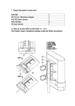
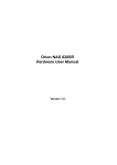
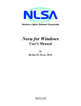
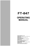
AutoTracker Satellite Antenna Tracking and Tuning Controller Users Guide Revision I – November 1999 Copyright Endeavour Electronics 1994 - 1999 Part Number EE100M Endeavour Electronics 157 Catamount Road Tewksbury, MA 01876 Tel. : (978) 851-5661 Fax: (978) 851-8964 e-mail: [email protected] www.endeavour-usa.com Warranty Information All products manufactured by Endeavour Electronics are warranted against defective materials and workmanship for a period of one year from the date of delivery to the original purchaser. Any product that is found to be defective within the warranty period will, at the option of Endeavour Electronics, be repaired or replaced. This warranty does not apply to products damaged by improper use. Warning Endeavour Electronics assumes no liability for damages consequent to the use of this product. Disclaimer Information furnished by Endeavour Electronics is believed to be accurate and reliable. However, Endeavour Electronics assumes no responsibility for the use of such information nor any infringements of patents or other rights of third parties that may result from its use. Table of Contents Chapter 1 Introduction General Description ................................................ Electrical Specifications .......................................... Front and Rear Panel Layouts ……………………. Connector Pin Assignments .................................... Chapter 2 1 1 2 2-4 Installation Unpacking and Inspecting ...................................... 5 Introduction ............................................................ 5 Serial Port Connections .......................................... 5 Rotator Connections ............................................... 6-7 Microphone Up/Down Doppler Correction ............. 8-9 Serial Port Doppler Correction ............................... 9-11 Chapter 3 Operation Introduction ............................................................. 12 Antenna Positioning ................................................ 12 Microphone Up/Down Doppler Correction ............. 12-13 Serial Port Doppler Correction ................................ 13 Chapter 4 Software Specification Overview .................................................................. 14 Software Command Set ........................................... 14-15 Minimum Tracking Requirements............................. 16-17 Optional Tracking Requirements………………….. 17-18 Appendix A Factory Returns/Contacting Endeavour Appendix B Compatible Tracking Software Appendix C Cable and Connector Diagrams Chapter 1 Introduction General Description The Endeavour Electronics AutoTracker interface is an automated satellite antenna positioning and Doppler frequency compensation controller. It is typically used by amateur radio and weather satellite operators to automatically position their satellite antenna array, in both azimuth and elevation, and to control the operating frequency of ground station radio equipment during an amateur radio or weather satellite pass. The AutoTracker interface works in conjunction with a host computer running a satellite tracking program configured for use with AutoTracker. The AutoTracker interface communicates with the host computer over a 9600 baud serial communications link. Azimuth, elevation and frequency data is passed from the host computer to the AutoTracker interface which in turn, commands proper antenna movement, and frequency control of the ground station radio equipment. Software tracking programs compatible with the AutoTracker interface are currently available for PC compatible computers (DOS and Windows), as well as the Apple Macintosh. The AutoTracker interface features flexible rotator control circuitry, which is designed to be compatible with most popular rotators. The AutoTracker interface connects directly to the remote control interface connector of the Yaesu G5400B and G5500, and to many other rotator types using external relays. Four relay driver outputs are provided to control the direction of movement of both an azimuth and elevation rotator. Two additional relay driver outputs are provided to control the electrically actuated brake mechanism in both rotators, if required. Two analog inputs are provided to measure the azimuth and elevation positions of the antenna array. These analog inputs are configured to measure an input voltage in the range of 0 → 5VDC. In addition to automatic control of antenna positioning, the AutoTracker interface will also allow the satellite operator to control the frequency of the radio equipment (up to two radios) used in the satellite ground station. Frequency control can be accomplished by using either the microphone Up/Down frequency control push buttons commonly found on most modern radios, or via the serial interface control port of radios that are so equipped. The AutoTracker interface has two microphone Up/Down control ports (Radio 1 and Radio 2). Four digital logic outputs (Up #1, Down #1, Up #2, Down #2) are provided to control the Up/Down frequency control push buttons of the ground station equipment. The AutoTracker interface has two serial interface control ports for radio control (Radio 1 and Radio 2). These two serial ports (independent of those associated with the host computer) are provided to control the frequency of computer controlled ground station radio equipment. These serial control ports may be user configured for either TTL or RS-232C levels. AutoTracker Electrical Specifications Power Consumption: Min. Az. Resolution: Min. El. Resolution: Host Compatibility: Analog Input Range: Digital Output Sink: Operating Temperature: Humidity: 100mA @ 12VDC 1.4 ° 0.7 ° 9600,8,N,1 Serial Port (fixed) 0 → 5VDC (Voltages in excess of 5.6V may damage the AutoTracker) 60mA at 60V (Rotator Control and Up/Down Frequency Control) 0 to 50 °C 0 to 90% non-condensing AutoTracker User Manual 1 Nov. 1999 AutoTracker Front Panel Layout The front panel layout of the AutoTracker interface are shown below. The front panel contains the main power switch, a power indicator LED, and four status indicators for the internal high current relay drivers. The current state (On/Off) of each driver (Azimuth Left/Right, and Elevation Up/Down) is displayed by these indicators. Right Endeavour Electronics AutoTracker Left Right Up Azimuth Down Power Elevation AutoTracker Front Panel Layout AutoTracker Rear Panel I/O Connectors and Pin Assignments The rear panel layout of the AutoTracker interface are shown below. The rear panel contains the power input jack (+12VDC), the console serial port (9 Pin Type “D” Male), the radio tuning ports (5 Pin DIN mic-click and serial), and the rotator control port (9 Pin Type “D” Female). Radio Tuning 12VDC Console Rotator Microphone Serial AutoTracker Rear Panel Layout DC Power Input Connector The AutoTracker power input connector is a 2.1mm coaxial jack. The center terminal of the jack is positive, while the outer ring is negative. The power input connector will a accept 9 - 15 VDC input. Console Serial Connector (Male 9 Pin "D") The AutoTracker is configured as Data Communications Equipment (DCE), the technical term for an RS-232C modem. Most computers are configured as Data Terminal Equipment (DTE). AutoTracker will communicate with the host computer using a standard "modem" serial cable. Pin No. and Function 1. "On-Line" (Pulled "Hi" when AutoTracker is ON) 2. Rxd (Host → AutoTracker) 3. Txd (AutoTracker → Host) 4. Not Connected AutoTracker User Manual 2 Nov. 1999 Console Serial Connector (Male 9 Pin "D") - Continued 5. Ground 6. DSR (Pulled "Hi" when AutoTracker is ON) 7. Not Connected 8. CTS (Pulled "Hi" when AutoTracker is ON) 9. Not Connected Rotator Control Connector (Female 9 Pin "D") The AutoTracker interface is designed to be connected directly to the Yaesu G5400B and G5500 rotator controllers. It can also be used to control rotators from other manufacturers using external drive relays. A cable wiring description is included for constructing a Yaesu G5400B/G5500 interface cable. Pin No. and Function 1. Left Output 2. Right Output 3. Azimuth Brake (See Note 1) 4. Up Output 5. Down Output 6. Elevation Brake (See Note 1) 7. Azimuth Voltage In (See Note 2) 8. Elevation Voltage In (See Note 2) 9. Ground Note 1: Brake Controls are activated/de-activated 1 second before, and 3 seconds after Azimuth/Elevation Rotation. Not used on Yaesu Rotor Controllers! Note 2: 0 → 5 V input only. Do not exceed this range, or damage to AutoTracker will result! Radio Tuning Connectors The AutoTracker interface has two means for controlling the frequency of one or both of the radios being used for satellite communications. The first method utilizes the Up/Down frequency control inputs found on the microphone connector of most modern radios. During the satellite pass, the AutoTracker interface controls these inputs automatically to compensate for the effects of Doppler shift during the satellite pass. The second method of automatic frequency control utilizes the radios RS-232C computer control port for frequency tuning. Many modern radios (particularly base station types) include a computer control interface port. The AutoTracker interface has two serial control ports for controlling the frequency of ground station radio equipment in this way. Microphone Tuning (Left Hand 5 Pin DIN) Pin No. and Function 1. Bump UP #1 2. Ground 3. Bump UP #2 4. Bump DOWN #1 5. Bump DOWN #2 (Radio #1) (Radio #2) (Radio #1) (Radio #2) AutoTracker User Manual 3 Nov. 1999 Serial Port Tuning (Right Hand 5 Pin DIN) Pin No. and Function 1. Serial IN #1 2. Ground 3. Serial IN #2 4. Serial OUT #1 5. Serial OUT #2 (Radio #1) (Radio #2) (Radio #1) (Radio #2) AutoTracker User Manual 4 Nov. 1999 Chapter 2 Installation Unpacking and Inspecting The following items should be included in the shipping container: (1) AutoTracker Interface (1) 9 Pin Rotator Control Cable (Single Ended) (1) 5 Pin DIN Plug (Mic-Click Frequency Control) (1) 2.1 mm Coaxial Power Plug (1) Instruction Manual (1) Product Registration Card If any items are missing from your shipment, please contact the Endeavour Electronics factory immediately to remedy the situation. Note: if accessories are purchased, some of these items may not be included. Introduction The AutoTracker interface is designed to control the Yaesu G5400B and G5500 Azimuth/Elevation rotators directly, or other rotator types using external relays. The analog input range of the interface is 0 →5VDC. It is up to the user to ensure that the rotator being controlled outputs this voltage range to indicate the azimuth and elevation position measurement. If you are using the Yaesu G5400B or G5500 rotator system, you must verify that the output voltages corresponding to the azimuth and elevation position follows this guideline. To adjust the Yaesu G5400 controller, position the azimuth to full right (180°), and the elevation to full up (180°). If your installation limits the maximum elevation to 90°, move to that position. On the back of the Yaesu controller, there are two Output Voltage Adjustment controls, for azimuth and elevation, respectively. Connect a voltmeter to pin #6 (Azimuth Voltage Output) and Pin #8 (Gnd). Adjust the Azimuth Output Voltage Adjustment until the voltmeter indicates 5.00VDC. Connect a voltmeter to pin #1 (Elevation Voltage Output) and pin #8 (Gnd). Adjust the Elevation Output Voltage Adjustment until the voltmeter indicates 5.00VDC for 180° or 2.50VDC for 90° During power up, the AutoTracker interface will sequence its front panel indicators to provide a visual indication that the hardware is operational. Serial Port Connections Connect the Console Serial Port of the AutoTracker interface to the desired serial port on the host computer. A "modem" style serial cable is the appropriate type to use and is available at most computer retailers nationwide. If you are unsure of this connection, serial cables with both 9 and 25 pin termination are available from Endeavour Electronics. Contact the factory for more details. The serial port connection can be tested with a terminal emulation program, such as ProComm Plus, with serial port parameters configured for 9600, 8, N, 1. If you are unfamiliar with this procedure, consult your terminal program manual. If there are no unused serial ports on your computer, consider replacing your serial port connected mouse with a bus connected mouse. Two additional serial ports (COM3 and COM4) can AutoTracker User Manual 5 Nov. 1999 also be added to your computer with the appropriate hardware interface. This interface can be obtained from: Quatech Incorporated. More information can be obtained at: www.quatech.com. Inquire about part #DSC-100. When the AutoTracker interface is communicating properly with the host computer, it will send a "sign-on" message during power up. When configured properly, you should see the following display after applying power to the AutoTracker interface. AutoTracker Satellite Antenna Tracking and Tuning Controller with Serial Tuning & WiSP Support Endeavour Electronics Tewksbury, MA Tel.: (978) 851-5661 Fax: (978) 851-8964 e-mail: [email protected] www.endeavour-usa.com System Software Version X.X Copyright 1994 - 1999 *** Self Test in Progress *** *** RAM Test Successful *** Note: The most common difficulty with this step is the use of an incorrect serial cable. Be sure that you are using an RS-232C "modem" type serial cable. The second most likely cause of problems is a serial port or serial port configuration problem. Test the serial port with another device, if available, to ensure that it is working correctly. Finally, consult the terminal emulation program manual to check the port configuration. Rotator Connections Yaesu G5400B and G5500 Rotator Controllers The AutoTracker interface will control virtually any type of antenna rotator. To be controlled, the candidate rotator must satisfy two conditions. It must have independent control switches for each direction of rotator movement, and it must use a feedback potentiometer in the rotor head to send back to the control box a voltage corresponding to the current rotator position. The Yaesu G5400B and G5500 rotators have internal relays for the purpose of external control. These rotors also provides adjustable feedback voltages to an external controller, like AutoTracker. The Yaesu G5400B and G5500 rotator systems can be connected directly to the AutoTracker interface. All that is necessary for the user to do is to connect the appropriate Yaesu rotator control cable between the female 9 pin "D" type rotator control connector on the rear panel of the AutoTracker to the 8 pin "DIN" type remote control connector on the rear panel of the Yaesu G5400B/G5500 rotator control unit. This cable can be fabricated by the user as described below, or can be purchased separately from Endeavour Electronics. AutoTracker User Manual 6 Nov. 1999 Yaesu G5400B and G5500 Rotor Interface Cable Wiring AutoTracker Rotator Connector 9 Pin "D" Female Yaesu G5400B/G5500 "External Control" Connector (8 Pin DIN) 1. Left Output 2. Right Output 4. Up Output 5. Down Output 7. Azimuth Voltage In 8. Elevation Voltage In 9. Ground 4. Left Input 2. Right Input 3. Up Input 5. Down Input 6. Azimuth Output 1. Elevation Output 8. Ground =====> =====> =====> =====> =====> =====> =====> When building this cable, use the rotor interface cable supplied by Endeavour Electronics, and the 8 Pin DIN connector supplied with your Yaesu G5400B/G5500 rotator. Note: You must use an ohmmeter or continuity tester to determine the correct wire color/pin number relationship on the supplied rotor interface cable. Unfortunately, our cable supplier uses random wire colors when fabricating these cables. Note: When connected to the Yaesu G5500 rotor controller, configuration jumper J3 inside the AutoTracker chassis must be installed. Non-Yaesu Rotator Controllers As shipped from the factory, the AutoTracker interface is configured to interface with the Yaesu rotator directly. If you are controlling a rotator other than the Yaesu G5400B or G5500, an internal jumper must be placed on multi pin header J4 inside a Rev. 1.0 AutoTracker interface. Looking at the rear of the AutoTracker interface, this jumper must be placed across the bottom two pins of the left hand row of pins. On Rev. 2.0 AutoTracker interfaces, configuration jumper #1 must be installed. The default (no jumper either Rev. 1.0 or 2.0) configures the AutoTracker for Yaesu rotator control only. If you wish to control a non-Yaesu rotator with the AutoTracker interface, please refer to the attached "Non-Yaesu Rotator Connection Schematics". An external relay must be placed in parallel with each rotator control switch. These relays allow the AutoTracker interface to control the rotators directly; in effect simulating the manual closure of the control switch. A relay is required for each direction of movement. Typically, at least four or five relays are required to control the rotator(s) completely. (Left, Right, Up, Down, and Brake) Ideally, these relays should be placed inside the rotator control box. The AutoTracker interface must also be provided with a 0 → 5V DC voltage signal that corresponds to the current azimuth or elevation. Frequently, the voltage output of the rotator falls outside this range, and must be scaled to be compatible with the AutoTracker analog input. You must measure the rotor output voltage to verify that it never exceeds 5.0V. A potentiometer configured as a voltage divider, can be added to the rotator control box to scale the rotor output voltage to the desired range. (One each for azimuth and elevation) The wiper of the rotor feedback potentiometer is connected to one of the rotor control box rear panel connections. This connection is connected to one end of the scaling potentiometer. The other end of the scaling potentiometer is connected to ground. The scaling potentiometer wiper is then connected to the analog input of the AutoTracker interface. Before making this connection, you must do the following: While measuring the feedback voltages of the azimuth and elevation rotators, rotate the rotors to a position that results in a maximum feedback voltage. Typically, this is full elevation UP and full azimuth RIGHT. AutoTracker User Manual 7 Nov. 1999 Adjust the scaling potentiometers added to the azimuth and elevation analog voltages so that the voltage at the scaling pot wiper (with respect to ground) is 5.0V. A relay interface board is currently available from Endeavour Electronics to facilitate the connection of the AutoTracker interface to other rotator types. Extreme care should be exercised when working inside the control box. Lethal voltages exist that can kill you. Microphone Up/Down Doppler Correction The AutoTracker interface allows the user the ability to control the frequency of ground station equipment using the microphone Up/Down push buttons found on many radios in satellite operation today Each time the tracking program running on the host computer calculates a change in frequency of greater than specified (typically: 10 →100 Hz) on either the uplink or the downlink, an appropriate mic-click stepping signal will be generated on the appropriate Doppler Up/Down control line. In general, the VHF radio in the ground station setup should be connected to port #1, and the UHF radio should be connected to port #2. In the case where only one radio is being controlled, the UHF uplink to Oscar 13 for example, that radio should be connected to port #1. When a transceiver is being used, Port #1 should be the only mic-click port connected! The Up/Down control outputs of the AutoTracker interface may be directly connected to the microphone Up/Down inputs of your radio. The AutoTracker interface will generate a negative going signal for Kenwood and Icom radios, and a positive going signal for Yaesu radios. Yaesu radios do require the installation of external "pull-up" resistors on the mic-click inputs. Your tracking program must also support the "Radio Type" command in the AutoTracker firmware. Connections to the microphone Up/Down inputs on Yaesu radios should be made through a switch. This allows the inputs to be disconnected from the AutoTracker mic-click output drivers during power-up. If the Yaesu Up/Down inputs are connected directly to the AutoTracker, the Yaesu radio will frequency "step" until the "Radio Type" command is received, and the mic-click outputs are re-initialized. Typical connection diagrams for these radios (Kenwood, Icom and Yaesu) are shown below. If you have any questions about connecting mic-click tuning, or if your radio(s) is not on this list, please contact the Endeavour Electronics factory for assistance. If mic-click tuning is not implemented at your station, the mic-click outputs can be used for controlling external hardware devices. Each of the (4) outputs can be independently controlled ON/OFF. The current sink capability of these outputs is the same as that of the rotor control output drivers (60mA @ 60V). This is sufficient to drive most signal type relays directly. Please contact the Endeavour Electronics factory for more information. Kenwood TS-790A Mic-Click Tuning Connections AutoTracker Kenwood TS-790A 5 Pin DIN Connector 8 Pin Microphone Connector Pin 1. (Up #1) ====> Pin 4. (Down #1) ====> Pin 2. (Ground) ====> Pin 4. (connected directly to AutoTracker Pin #1) Pin 3. (connected directly to AutoTracker Pin #4) Pin 7. (connected directly to AutoTracker Pin #2) AutoTracker User Manual 8 Nov. 1999 Yaesu FT-726R/FT-736R/FT-847 Mic-Click Tuning Connections AutoTracker Yaesu FT-726R/FT-736R/FT-847 5 Pin DIN Connector 8 Pin Microphone Connector Pin 1. (Up #1) ====> Pin 4. (Down #1) ====> Pin 2. (Ground) ====> Pin 1. (Must be pulled up with a 3K resistor to Yaesu Mic Pin #2) Pin 3. (Must be pulled up with a 3K resistor to Yaesu Mic Pin #2) Pin 7. (connected directly to AutoTracker Pin #2) Icom IC-820H/IC-970H Mic-Click Tuning Connections AutoTracker Icom IC-820H/IC-970H 5 Pin DIN Connector 8 Pin Microphone Connector Pin 1. (Up #1) ====> Pin 4. (Down #1) ====> Pin 2. (Ground) ====> Pin 3. (Connected directly to AutoTracker Pin #1) Pin 3. (Connected to AutoTracker Pin #4 through a 470 ohm resistor!) Pin 6. (Connected Directly to AutoTracker Pin #2) Serial Port Doppler Correction The AutoTracker interface allows the user the ability to control the frequency of ground station equipment using the computer control port found on many radios in satellite operation today. Each time the tracking program running on the host computer calculates a change in frequency of greater than a specified amount (typically 10→100 Hz) on either the uplink or the down link, a serial command formatted for the radio type will be sent to the appropriate Doppler serial control output port. In general, the VHF radio in the ground station setup should be connected to port #1, and the UHF radio should be connected to port #2. In the case where only one radio is being controlled, the UHF uplink to Oscar 13 for example, that radio should be connected to port #1. When a transceiver is being used, Port #1 should be the only serial port connected! The serial control ports on the AutoTracker interface can be switched by the user between TTL and RS-232C levels, and may be directly connected to the computer control port of most radios. Frequently, most radio manufactures use TTL levels internally, and require the user to purchase an expensive (>$100.00) TTL to RS-232 converter to connect the radio to the outside world. The AutoTracker interface eliminates this unnecessary expense. Some Kenwood radios (TS-790A) use an inverted serial port data scheme. The inverted/non-inverted data scheme can also be user selected. On Rev. 1.0 AutoTracker boards, please contact the Endeavour factory for assistance when making these changes. On Rev. 2.0 boards, the data scheme are controlled by (4) board mounted jumpers. Please consult the table below, for setting information. Your tracking program must also support the "Radio Type" command in the AutoTracker firmware. Serial baud rates are fixed in the AutoTracker firmware. Kenwood and Yaesu radios should be configured for a serial transmission rate of 4800 baud, while Icom radios should be configured for 1200 baud. Typical connection diagrams for these radios (Kenwood, Icom and Yaesu) are shown below. If you have any questions about connecting serial port tuning, or if your radio(s) is not on this list, please contact the Endeavour Electronics factory for assistance. AutoTracker User Manual 9 Nov. 1999 Serial Port Jumper Settings (Rev. 2.0 Boards only!) Jumper J7 Jumper J8 Jumper J10 Jumper J11 RS-232 TTL Short 2 & 3 Short 2 & 3 Short 1 & 2 Short 1 & 2 Non-Invert Invert Short 2 & 3 Short 2 & 3 Short 1 & 2 Short 1 & 2 Note: Kenwood Radios should be configured for Inverted TTL levels, all Yaesu and Icom radios should be configured for Non-Inverted TTL levels. Kenwood TS-790A Serial Port Tuning Connections AutoTracker Kenwood TS-790A 5 Pin DIN Connector 6 Pin DIN Serial Port Connector Pin 1. (In #1) ====> Pin 4. (Out #1) ====> Pin 2. (Ground) ====> Pin 2. (connected directly to AutoTracker Pin #1) Pin 3. (connected directly to AutoTracker Pin #4) Pin 1. (connected directly to AutoTracker Pin #2) Yaesu FT-726R/FT-736R Serial Port Tuning Connections AutoTracker Yaesu FT-726R/FT-736R 5 Pin DIN Connector 6 Pin DIN Serial Port Connector Pin 1. (In #1) ====> Pin 4. (Out #1) ====> Pin 2. (Ground) ====> Pin 4. (connected directly to AutoTracker Pin #1) Pin 2. (connected directly to AutoTracker Pin #4) Pin 1. (connected directly to AutoTracker Pin #2) The Yaesu FT-736 requires that several procedural steps be followed for proper automatic frequency tuning operation. These steps should be followed before a satellite pass begins, and before automatic tracking and tuning with the AutoTracker interface is enabled. To begin, first determine the desired band of operation (2M, 70CM, etc.) for both the uplink and downlink radio frequencies. Engage the satellite mode (SAT selector knob), and position the selector knob to "TX". Select either VFO A or VFO B. The frequency displayed on the FT-736 tuning display should be in the same band as the desired uplink frequency. If it is not, the reverse function key will allow you select the desired uplink band. AutoTracker User Manual 10 Nov. 1999 Yaesu FT-847 Serial Port Tuning Connections AutoTracker Yaesu FT-847 5 Pin DIN Connector 9 Pin DB-9 Male Serial Port Connector Pin 1. (In #1) ====> Pin 4. (Out #1) ====> Pin 2. (Ground) ====> Pin 3. (connected directly to AutoTracker Pin #1) Pin 2. (connected directly to AutoTracker Pin #4) Pin 5. (connected directly to AutoTracker Pin #2) Icom IC-820H/IC-970H Serial PortTuning Connections AutoTracker Icom IC-820H/IC-970H 5 Pin DIN Connector 1/8" CAT Serial Port Connector Pin 1. (In #1) ====> Pin 4. (Out #1) ====> Pin 2. (Ground) ====> Tip. (Connected directly to AutoTracker Pin #1) Tip. (Connected directly to AutoTracker Pin #4 ) Outer Ring (Connected directly to AutoTracker Pin #2) Note: Icom radios send and receive serial data on one physical wire connection. This wire is connected to both the AutoTracker In #1 and Out #1 serial port connections. The Icom IC-820/970 requires that several procedural steps be followed for proper automatic frequency tuning operation. These steps should be followed before a satellite pass begins, and before automatic tracking and tuning with the AutoTracker interface is enabled. To begin, first determine the desired band of operation (2M, 70CM, etc.) for both the uplink and downlink radio frequencies. The frequency displayed on the IC-820/970 Main tuning display should be in the same band as the desired uplink frequency, and the frequency displayed on the Sub tuning display should be in the same band as the downlink frequency. If it is not, the M/S function key should be used to swap the Main/Sub bands. AutoTracker User Manual 11 Nov. 1999 Chapter 3 Operation Introduction The satellite tracking program running on the host computer sends the AutoTracker interface a number of setup parameters when automatic antenna positioning is activated. These parameters include the home azimuth and home elevation that define the "parked" position the antenna array returns to when not being controlled, the azimuth window and elevation window that define the degree of accuracy that the AutoTracker interface will position the antenna array to, relative to the commanded target azimuth and elevation, and the max elevation that defines the maximum elevation that the AutoTracker will command. Following this initial set-up, the tracking program will begin to send antenna positioning information, and Doppler frequency compensation information to the AutoTracker interface, if the selected satellite is currently "in view" of the ground station location. For high altitude satellites in elliptical orbits this period may last 10 → 15 hours, while for the Low Earth Orbit (LEO) satellites, it may last for only 10 minutes. Before tracking and tuning should be attempted, all of the initial setup parameters required by the AutoTracker interface should be defined from within the tracking program! Consult the tracking program manual for more information! Antenna Positioning Following the setup commands described above, the host computer begins to send the AutoTracker interface azimuth and elevation position updates. This only occurs when the selected satellite has an elevation greater than -5 °. Tracking begins at this point so that the azimuth rotator is correctly positioned when the satellite becomes visible above the horizon (elevations > 0°), eliminating the transit time of the azimuth rotator from the parked position at the start of the pass. When the elevation angle is >-5 degrees, the satellite is considered "out of view" and no tracking takes place. Satellite tracking will continue until the elevation drops below -5,° at which time the rotators will return to their previously user defined "parked" position. The accuracy of the antenna positioning is only as good as the accuracy of your PC's internal real time clock and keplerian element data file. Update your system clock every 23 days (PC clocks are notoriously inaccurate!), and your keplerian elements at least once a week. Accurate time information can be obtained via the National Bureau of Standards (NIST) radio station WWV in Boulder, CO on a frequency of 5.000, 10.000 and 15.000 MHz. Keplerian elements are available via many packet radio BBS's and commercial dial-up Bulletin Boards. Microphone Up/Down Doppler Correction The initial operating frequencies are input to the tracking program at the beginning of the satellite pass. These frequencies must also be manually selected on the ground station radio equipment. Information about the mic-click step size (mic-click sensitivity - see software specification) of the radio connected to the AutoTracker interface is also input to the tracking program. During the pass, Doppler frequency correction data is sent from the host computer to the AutoTracker interface each time the apparent operating frequency due to the motion of the satellite relative to the ground station exceeds a user specified amount (Doppler correction tolerance - see software specification). The AutoTracker interface will allow two frequencies to be independently compensated for Doppler frequency shift. The type of satellite you are operating will dictate the most desirable Doppler compensation protocol. Sometimes it is AutoTracker User Manual 12 Nov. 1999 desirable to control both the uplink and the downlink frequencies. At other times a satellite operator may desire to control only the uplink frequency. Consult an Amateur Satellite group such as AMSAT, to determine the best operating practice for each satellite you intend to operate. Information about setting the Doppler frequency control mode should also be available in the manual of your tracking program. When only one radio is being controlled by the AutoTracker interface, it should be connected to the Bump Up #1/Bump Down #1 connections on the rear panel of the AutoTracker interface. The accuracy of the antenna positioning is only as good as the accuracy of your PC's internal real time clock and keplerian element data file. Update your system clock every 2-3 days (PC clocks are notoriously inaccurate!), and your keplerian elements at least once a week. Accurate time information can be obtained via the National Bureau of Standards (NIST) radio station WWV in Boulder, CO on a frequency of 5.000, 10.000 and 15.000 MHz. Keplerian elements are available via many packet radio and dial-up Bulletin Boards. If mic-click tuning is not implemented at your station, the mic-click outputs can be used for controlling external hardware devices. Each of the (4) outputs can be independently controlled ON/OFF. The current sink capability of these outputs is the same as that of the rotor control output drivers (60mA @ 60V). This is sufficient to drive most signal type relays directly. Please consult the "I" command in the software specification for programming information. Please contact the Endeavour Electronics factory for more information. Serial Port Doppler Correction The AutoTracker Serial Tuning Option will allow the satellite operator to control the frequency of the ground station radio equipment via the radios computer control input. The AutoTracker interface will select the initial operating frequency at the beginning of the satellite pass, and adjust the frequency throughout the pass to compensate for Doppler shift. Prior to the beginning of the satellite pass, the initial operating frequencies and the Doppler tuning tolerance (Doppler correction tolerance - see software specification) is specified within the satellite tracking program. During the pass, Doppler frequency correction data is sent from the host computer to the AutoTracker interface each time the apparent operating frequency due to the motion of the satellite relative to the ground station exceeds a user specified amount. The AutoTracker interface will allow two frequencies to be independently compensated for Doppler frequency shift. The type of satellite you are operating will dictate the most desirable Doppler compensation protocol. Sometimes it is desirable to control both the uplink and the downlink frequencies. At other times a satellite operator may desire to control only the uplink frequency. Consult an Amateur Satellite group such as AMSAT, to determine the best operating practice for each satellite you intend to operate. Information about setting the Doppler frequency control mode should also be available in the manual of your tracking program. When only one radio is being controlled by the AutoTracker interface, it should be connected to the Serial In #1/Serial Out #1 connections on the rear panel of the AutoTracker interface. Currently, only frequency information is controlled by the AutoTracker interface. The Main Band /Sub Band, Duplex Mode, Mode, etc. selections on the ground station radio equipment are also programmed automatically by the tracking software. On the Icom IC-820H, it is necessary that the user manually select the proper band (2M or 70cm) for the Main and Sub bands. The AutoTracker will automatically program the desired uplink and downlink frequencies, but it will not program a 2M frequency to the Main or Sub band if a 70cm is already selected, and vice versa. Note: When running a Windows based tracking program, such as WinTrak Pro, it is possible to run the Windows satellite tracking program "in the background", while running PB/PG in a DOS window "in the foreground". AutoTracker User Manual 13 Nov. 1999 Chapter 4 Software Specifications Overview There are a number of software commands that the AutoTracker interface will respond to. The interface will accept a number of setup commands, a command to position the azimuth and elevation rotators, a command to respond with the current position of the azimuth and elevation rotators, and two sets of commands (Microphone Up/Down and Serial Tuning) to command Doppler frequency correction. AutoTracker Software Command Set Setup Commands: HM:000,000<CR> Sets the home position that the azimuth and elevation rotators will return to when not tracking. Azimuth is sent first, Elevation second. Azimuth Range: 000→ → 360°° , Elevation Range: 000→ → 180°° Defaults: Azimuth = 000°° , Elevation = 000°° . WNDW:05,03<CR> Sets the azimuth and elevation windows. Larger numbers decrease antenna positioning accuracy, while minimizing rotator motor wear. Azimuth is sent first, Elevation second. Azimuth Range: 00→ → 05°° , Elevation Range: 00→ → 03°° Defaults: Azimuth = 05°° , Elevation = 03°° . MEL:090<CR> Sets the maximum antenna system elevation. Range: 060°° → 180°° . Default: 090°° RT: XXXXXX<CR> Sets the Radio Type. (eg. TS-790, FT-736, IC-970, IC-820, FT-847). character string. Default: TS-790. Tracking Commands: A:234,E:056<CR> G5500) CP?:<CR> Sets the desired target azimuth and elevation. Azimuth Range: 000°° → 360°° (0°° to 450°° for the Yaesu Elevation Range: 000°° → 180°° Request for the current azimuth and elevation position. Response: CPA:000,CPE:000<CR> AutoTracker User Manual 14 Nov. 1999 6 Tuning Commands: D:±001,±001<CR> Sets the direction and the magnitude (# of steps, not frequency) of the uplink (first) and downlink (second) doppler correction. For mic-click tuning. RM: 0,1<CR> Sets the Radio Mode(s). (eg. LSB, USB, FM). The uplink mode is sent first, followed by the downlink mode, according to the following format: 0=LSB 1=USB 2=FM 3=CW F0:00437015000<CR> Sets the absolute frequency of the uplink radio. For serial port tuning. F1:00145812000<CR> Sets the absolute frequency of the downlink radio. For serial port tuning. Note: Serial port (radio) tuning commands should have a short delay (250 mS typical) delay inserted following each command to allow the radio to respond. General Commands: I/O:0,1,0,1<CR> Sets the state of the (4) relay driver outputs. Normally these are used for mic-click tuning (see above), but can be used to control external hardware (antenna relays, downconverters, etc.) if mic-click tuning is not used. A "0" is relay activated, a "1" is relay de-activated. STOP<CR> Stops ALL rotor movement at present Azimuth and Elevation location. Immediate! VER:<CR> Requests the current AutoTracker software version number. Used to verify serial connection. Response: VXX<CR>. XX is version number. AutoTracker User Manual 15 Nov. 1999 Tracking Program Minimum Requirements • The tracking program should be configured to communicate with the AutoTracker interface at 9600 baud (fixed). The serial port communications parameters should be set to: 9600, 8, N, 1. • The tracking program should allow the user to enter a value for home azimuth, home elevation, and max elevation. These values are sent to the AutoTracker interface only once; the first time automatic antenna tracking/radio tuning is initiated within the tracking program. The AutoTracker interface will automatically return to the user defined home position 15 minutes following the last position command sent to the interface. • The tracking program should allow the user to enter a 6 character string which describes (model no.) the type of radio(s) connected to the AutoTracker interface. The tracking program should send the radio type string to the AutoTracker interface only once; the first time that automatic antenna tracking/radio tuning is initiated within the tracking program. Acceptable entries include: TS-790, FT-736, IC-970, and IC-820 • The tracking program should allow the user to enter a value for doppler correction tolerance. This is the minimum incremental amount of frequency change due to doppler shift that will cause the tracking program to send a frequency correction command (mic-click or serial) to the AutoTracker interface. Acceptable values should be in the range of 10 Hz to 5000 Hz. For example: if this value is set to 100, the tracking program should ignore frequency changes within a 100 Hz range centered on the current frequency (i.e. ±50 Hz). If either the uplink or downlink frequency changes by more than this amount, a frequency correction command is generated. Used internally by the tracking program, not sent to the AutoTracker interface. • The tracking program should allow the user to enter a value for mic-click sensitivity. This is the amount that the frequency of the users radio(s) changes each time the mic-click input is activated. This value is used by the tracking program to determine the number of mic "clicks" required to achieve a desired frequency change. Acceptable values should be in the range of 10 Hz to 1000 Hz. For example: if the minimum frequency change has been observed (see above), the tracking program will command a mic-click frequency correction. The number of mic "clicks" will be determined by the absolute value of the frequency change desired, and by the mic-click sensitivity. If the mic-click sensitivity is 100 Hz, and the desired frequency change is 1000 Hz, then 10 mic "clicks" are commanded. Used internally by the tracking program, not sent to the AutoTracker interface. • The tracking program should send the target azimuth and elevation to the AutoTracker interface when automatic antenna positioning is enabled, and real time mode is selected. The AutoTracker interface will only command antenna movement when the target elevation is greater than -5°, and less than the max elevation. • The tracking program may, at any time, request the current antenna position from the AutoTracker interface. • The tracking program should allow the user to enter values for both the uplink and downlink operating frequencies. These frequencies are sent to the radio(s) initially and are updated periodically as required to compensate for doppler shift. In the case of mic-click doppler correction, the initial radio frequencies are entered manually by the user. AutoTracker User Manual 16 Nov. 1999 • The AutoTracker interface may be used to control external hardware via the mic-click outputs, if they are not being used for tuning. Control of the (4) mic-click relay driver outputs is accomplished using the I/O command. • The tracking program can command the immediate stoppage of all rotor movement using the STOP command. Note: All commands must be in CAPITAL letters to be recognized, and all commands must be followed with a Carriage Return <CR>. Tracking Program Optional Requirements Some tracking programs allow for several doppler correction modes. Several suggested modes of doppler compensation are described below: Transponder Mode: In this mode, the user enters a downlink frequency only. This is the receiver frequency that the user wishes to operate. The tracking program should then calculate the uplink frequency required for the given downlink. This uplink frequency is based on the satellite transponder translation constant, and the uplink and downlink doppler shift. The uplink frequency is found as follows: Satellite Tx Freq. = Downlink Freq. +/- downlink doppler Satellite Rx Freq. = Translation constant - Satellite Tx Freq. Uplink Freq. = Satellite Rx Freq. +/- uplink doppler The tracking program should program both the downlink and uplink frequencies at the beginning of the pass (or when initiated by the user). After the initial frequencies are programmed, only the uplink is adjusted for doppler during the pass. THE DOWNLINK REMAINS FIXED. There also should be a means for the user to "nudge" the UPLINK frequency up or down slightly to fine tune the uplink/downlink frequency combination. For "mic-click" tuning, the user manually programs his radio with the desired downlink frequency, and the uplink frequency calculated by the tracking program (tracking program should display both). During the pass, only the uplink frequency is adjusted using "mic-click" tuning. Transponder mode is used primary with the SSB/CW analog satellites (e.g. AO-13). Normal Mode: In this mode, the user enters both the satellite receiver frequency and the satellite transmitter frequency. The tracking program should then calculate the uplink and downlink radio frequencies required. These frequencies are based on the satellite Rx /Tx frequencies and uplink/downlink doppler, according to the following: Uplink Freq. = Satellite Rx Freq. +/- uplink doppler Downlink Freq. = Satellite Tx Freq. +/- downlink doppler AutoTracker User Manual 17 Nov. 1999 The tracking program should program both the downlink and uplink frequencies at the beginning of the pass (or when initiated by the user). After the initial frequencies are programmed, both the uplink and downlink frequencies are adjusted for doppler during the pass. There should be a means for the user to "nudge" the DOWNLINK frequency up or down slightly to fine tune the receiver for best digital data recovery. For "mic-click" tuning, the user manually programs his radio with the uplink and downlink frequencies calculated by the tracking program (tracking program should display both). During the pass, both the uplink and downlink frequencies are adjusted using "mic-click" tuning. Normal Mode is used primarily with the 9600 baud digital satellites (e.g. KO-23). AOS Mode (No Compensation): In this mode, the user enters both the satellite receiver frequency and the satellite transmitter frequency. The tracking program should then calculate the uplink and downlink radio frequencies required. These frequencies are based on the satellite Rx /Tx frequencies and uplink/downlink doppler, according to the following: Uplink Freq. = Satellite Rx Freq. +/- uplink doppler Downlink Freq. = Satellite Tx Freq. +/- downlink doppler The tracking program should program both the downlink and uplink frequencies at the beginning of the pass (or when initiated by the user). After the initial frequencies are programmed, all frequency programming is disabled. Instead, doppler compensation is done using external hardware. This mode takes advantage of the "closed loop" mic-click tuning control built into many digital satellite modems. "Mic-click" tuning is not used in this mode. AOS mode is used primarily with the 1200 baud digital satellites (e.g. AO-16). AutoTracker User Manual 18 Nov. 1999 Appendix A Factor Returns/Contacting Endeavour User Serviceable Parts With the exception of user installed software upgrades, there are NO user serviceable parts contained in the AutoTracker interface. If you encounter difficulty, please contact the Endeavour Electronics factory for assistance (see below). Return Requirements Before returning your AutoTracker for repair, please contact us by telephone or email, to notify our technical service personnel. If possible, we will attempt to diagnose and resolve your problem. If your problem cannot be resolved, you will be issued a Return Material Authorization Number (RMA), and asked to return your equipment. Please reference the RMA number on the outside of the shipping container, and on any correspondence regarding the equipment. When returning equipment for repair, please include a note containing the following information: Your Name, Address, and Telephone Number Date of Purchase Description of symptoms or problems If possible, pack the equipment in its original shipping container. Ship the package to the address shown below: Endeavour Electronics 157 Catamount Road Tewksbury, MA 01876-1212 Attn.: RMA # ______________ All returns should be sent to Endeavour postage prepaid and insured. Units in warranty will be returned postage paid and insured. Units out of warranty or damaged/modified will be returned postage due. AutoTracker User Manual 19 Nov. 1999 Contacting Endeavour Electronics Our office hours are from 7PM to 11PM Eastern Monday through Friday, and most of the day on Saturday. A telephone answering machine will be available during off hours to accept requests for orders and technical assistance. Our telephone number is (978) 851-5661, and our fax number is (978) 8518964. Our answering machine will be checked daily, and all calls will be answered promptly. We also check our email account daily, and respond immediately to incoming mail. Please send all order requests, and other correspondence to the following address: Endeavour Electronics 157 Catamount Road Tewksbury, MA 01876-1212 Tel.: (978) 851-8895 Fax: (978) 851-8964 email: [email protected] AutoTracker User Manual 20 Nov. 1999 Appendix B WinTrak Pro Satellite Tracking Program The WinTrak Pro satellite tracking program is designed to provide full support for all AutoTracker tracking and tuning functions. This appendix refers only to WinTrak Pro. If you are using an earlier version of WinTrak, please contact the author of WinTrak Pro for an upgrade. Information and upgrade pricing for WinTrak Pro is available from: Paul E. Traufler 111 Emerald Drive Harvest, AL 35749-9213 (256) 837-0084 (4 PM to 9 PM CST) email: [email protected] After completing the installation of the WinTrak Pro software package, it is necessary to configure WinTrak Pro for use with the AutoTracker tracking and tuning interface. Under the WinTrak Pro Options menu item, select Antenna This option window is used to configure the AutoTracker setup parameters for a particular antenna and radio installation. These values should set initially, and will remain valid until a change is made in the antenna/radio hardware. 1. Output Comm Port: This selection allows you to specify the serial communications (COM) port on the host computer that the AutoTracker is connected to. Select COM1→ COM4. 2. Home Positions: This selection allows you to specify the "Home" Azimuth and Elevation that the AutoTracker interface will position the antenna array following a satellite pass. Antennas will also return to this position if serial communication is lost with the WinTrak Pro program. 3. Deadbands/Limits a) Azimuth: Sets the tolerance of the azimuth positioning "window". Larger numbers decrease antenna positioning accuracy, while minimizing rotator motor wear. b) Elevation: Sets the tolerance of the elevation positioning "window". Larger numbers decrease antenna positioning accuracy, while minimizing rotator motor wear. c) Max. Elevation: Sets the maximum elevation of the antenna array. Check your system for obstacle clearance, etc. before specifying the maximum elevation. Max. Elevation of 90 degrees is recommended for AutoTracker User Manual 21 Nov. 1999 most installations. d) Doppler: Sets the minimum incremental amount of frequency change due to Doppler shift that will cause WinTrak Pro to send a frequency correction command (mic-click or serial) to the AutoTracker interface. Acceptable values should be in the range of 10 Hz to 5000 Hz. Example: if this value is set to 100, the tracking program will ignore frequency changes within a 100 Hz range centered on the current frequency (i.e. ±50 Hz). If either the uplink or downlink frequency changes by more than this amount, a frequency correction command is generated. 4. Radio Parameters: Sets the type of radio connected to the AutoTracker interface. Acceptable values include : the Kenwood TS-790, the Yaesu FT-736, and the Icom IC-970 and IC-820. 5. Mic-Click Step Size: Sets the mic-click sensitivity. This is the amount that the frequency of the users radio(s) changes each time the mic-click input is activated. This value is used by the tracking program to determine the number of mic "clicks" required to achieve a desired frequency change. Acceptable values should be in the range of 10 Hz to 1000 Hz. Example: if the minimum frequency change has been observed (see above), the tracking program will command a mic-click frequency correction. The number of mic "clicks" will be determined by the absolute value of the frequency change desired, and by the mic-click sensitivity. If the mic-click sensitivity is 100 Hz, and the desired frequency change is 500 Hz, then 5 mic "clicks" are commanded. 6. Antenna Offsets: Sets the amount (in degrees) that your antenna array is offset from true North (Azimuth), and zero degrees elevation (Elevation). Allows WinTrak Pro to compensate for an imperfectly aligned antenna array. Ideally, these should be zero! 7. AutoTracker Output Display: Selects the Antenna/Radio control panel type. Large display will show the current operating frequency on a simulated frequency display. Small display does not show operating frequencies. Large display is recommended! Click the SAVE push-button to update WinTrak Pro, and save your new entries. Under the WinTrak Pro Satellite menu item, select Transponder This option window is used to specify the transponder translation equations relevant to a particular satellite. The WinTrak Pro program will automatically use the transponder translation equation of the satellite to calculate the uplink frequency for a user entered downlink frequency when the satellite operator has specified "transponder mode" Doppler tuning. The user simply enters the satellite identifier, and all transponder translation constants supported by the particular satellite. 1. Use Transponder: This selection instructs the WinTrak Pro program to default to "transponder mode" Doppler tuning for the selected satellite. AutoTracker User Manual 22 Nov. 1999 2. Uplink/Downlink Mode: This selection defines the default Uplink and Downlink radio modes for the selected satellite. 2. Transponders This selection allows the satellite operator to define up to 10 satellite transponder constants for the selected satellite. The satellite transponder constant is the numeric value that relates the satellite uplink and downlink frequencies. For example, the Mode B transponder on the AO-13 satellite has a transponder constant of 581.398. This means that the uplink frequency can be found by subtracting the downlink frequency from 581.398, and vice versa. Therefore, the uplink freq. = 581.398 - downlink freq. for the AO-13 Mode B transponder. This relationship is slightly altered by Doppler shift on the uplink and downlink radio frequencies. The WinTrak Pro program, however, does compensate for Doppler shift when calculating the uplink radio frequency. Click the SAVE push-button to update WinTrak Pro and save your new entries. Under the WinTrak Pro Options menu item, select Manual Antenna Control This window option is used manually test the operation of the AutoTracker antenna positioning and radio tuning functions. In this window, the operator is allowed to manually command antenna movement, and radio tuning independent of any satellite tracking/tuning functions. This option window is VERY useful when verifying the proper operation and connection of the WinTrak Pro/AutoTracker serial interface, the rotor controller, and the ground station radio equipment. 1. Desired Azimuth and Elevation: This selection allows the user to manually select the position of the antenna array for automatic positioning. 2. Actual Azimuth and Elevation: This window displays the actual Azimuth and Elevation of the satellite antenna array (as reported by the AutoTracker interface. After a reasonable amount of antenna transit time, this display should agree with the selected desired azimuth and elevation. 2. Uplink/Downlink Radio Frequency: This selection allows the user to manually program the Uplink and Downlink radio frequencies. 3. Uplink/Downlink Radio Mode: This selection allows the user to manually select the Uplink and Downlink radio mode. Click the Send push-button to transmit these entries to the AutoTracker interface. Antenna Tracking and Radio Tuning is activated using the Antenna Positioning Icon AutoTracker User Manual 23 Nov. 1999 This window option is used for all automatic antenna tracking and radio tuning control functions. In addition to displaying the actual and desired antenna positions, this window also displays the current operating frequencies and Doppler shift. The Set Freqs/Modes control option gives the satellite operator complete automatic control of the ground station radio equipment. 1. Desired Azimuth and Elevation: This window displays the actual satellite azimuth and elevation as calculated by the WinTrak Pro satellite tracking program. 2. Actual Azimuth and Elevation: This window displays the actual Azimuth and Elevation of the satellite antenna array (as reported by the AutoTracker interface. After a reasonable amount of antenna transit time, this display should agree with the desired azimuth and elevation. 3. Set Freqs/Modes a) Uplink/Downlink Radio Frequency: This selection allows the user to manually program the Uplink and Downlink radio frequencies. b) Uplink/Downlink Radio Mode: This selection allows the user to manually select the Uplink and Downlink radio mode. c) Doppler Mode: This selection allows the user to select the type (method) of Doppler compensation required for the satellite being used. A description of each Doppler compensation mode is given below: Transponder Mode: In this mode, the user enters a downlink frequency only. This is the receiver frequency that the user wishes to receive the satellite. WinTrak Pro then calculates (click calculate uplink frequency) the uplink frequency required for the given downlink. This uplink frequency is based on the satellite transponder translation constant, and uplink/downlink Doppler shift. The WinTrak Pro program then sets the user specified downlink and the calculated uplink frequencies at the beginning of the pass (or when initiated by the user). After the initial frequencies are programmed, only the uplink frequency is adjusted for Doppler shift during the pass. THE DOWNLINK REMAINS FIXED. After the frequencies have been programmed (click Send) the user is given the opportunity to "fine tune" the calculated UPLINK frequency to optimize the uplink/downlink frequency combination. For "mic-click" tuning, the user manually programs his radio with the desired downlink frequency, and the uplink frequency calculated by WinTrak Pro (WinTrak Pro displays both). During the pass, only the uplink is adjusted using "mic-click" tuning. Transponder mode is used primary with the SSB/CW analog satellites (e.g. AO-13). Normal Mode: In this mode, the user enters both the satellite receiver frequency and the satellite transmitter frequency. WinTrak Pro then calculates the required uplink and downlink frequencies required, based on these frequencies and Doppler shift. The WinTrak Pro program will then program both the downlink and AutoTracker User Manual 24 Nov. 1999 uplink frequencies at the beginning of the pass (or when initiated by the user). After the initial frequencies are programmed, both the uplink and downlink frequencies are adjusted for Doppler during the pass. After the frequencies have been programmed (click Send) the user is given the opportunity to "fine tune" the calculated DOWNLINK frequency to optimize the receiver for best digital data recovery. For "mic-click" tuning, the user manually programs his radio with the uplink and downlink frequencies calculated by WinTrak Pro (WinTrak Pro displays both). During the pass, both the uplink and downlink are adjusted using "mic-click" tuning. Normal Mode is used primarily with the 9600 baud digital satellites (e.g. KO-23). No Doppler Compensation: In this mode, the user enters both the satellite receiver frequency and the satellite transmitter frequency. WinTrak Pro then programs the radio with the user entered uplink frequency, and the Doppler corrected downlink frequency. These frequencies are programmed at the beginning of the pass (or when initiated by the user), and are not adjusted for Doppler shift during the pass. After the initial frequencies are programmed, all frequency programming is disabled. Instead, frequency programming is often done externally. This mode takes advantage of the "closed loop" downlink tuning control built into many PSK digital satellite modems. "Mic-click" tuning is disabled in this mode. No Compensation mode is used primarily with the 1200 baud digital satellites (e.g. AO-16). AutoTracker User Manual 25 Nov. 1999 Appendix B WiSP Satellite Tracking Program Beginning with AutoTracker firmware release V3.0, the AutoTracker interface now supports the Windows based digital satellite program WiSP. The WiSP program sends antenna position and frequency tuning information to the AutoTracker interface during a digital satellite pass. Because this is the only information that is sent, it is necessary to configure the AutoTracker radio mode manually prior to operation with WiSP. To do this, use a terminal emulation program (such as Procomm) to communicate with the AutoTracker. Send the radio mode command that is appropriate for your radio to the AutoTracker. This must be done each time the AutoTracker is used by WiSP, unless the power is continuously applied to the interface. The command format required is shown below: RT: XXXXXX<CR> string. Sets the Radio Type. (eg. TS-790, FT-736, IC-970, IC-820). 6 character Default: TS-790. WiSP may be downloaded from the AMSAT-NA ftp site (ftp.amsat.org), and registered for a nominal fee. Monies collected through the sale of this software are used to fund future and ongoing Amateur space activities. After completing the installation of the WiSP software package, it is necessary to configure WiSP for use with the AutoTracker tracking and tuning interface. Under the WiSP Setup menu item, select Rotator Setup Now select EasyComm, and click OK. That’s all there is to it! Now WiSP will automatically position your antennas, and tune your radio(s) for optimal performance during a digital satellite pass. AutoTracker User Manual 26 Nov. 1999 Appendix C Cables and Connector Diagrams IBM PC Compatible Serial Cable (9 Pin Type “D” Female to 9 Pin Type “D” Female) Computer Conn. 2 3 5 AutoTracker Connector → → → 2 3 5 IBM PC Compatible Serial Cable (9 Pin Type “D” Female to 25 Pin Type “D” Female) Computer Conn. 3 2 7 AutoTracker Connector → → → 2 3 5 Macintosh Serial Cable (9 Pin Type “D” Female to 8 Pin Mini-DIN Male) Computer Conn. 3 4, 8 5 Shield AutoTracker Connector → → → → 3 5 2 Shield Note: Pins 4 and 8 are shorted together on the Macintosh end of the cable. AutoTracker User Manual 27 Nov. 1999