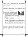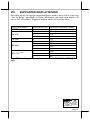
1
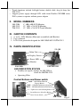
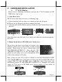
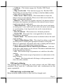
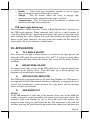
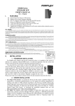
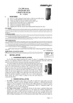
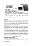
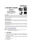
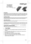
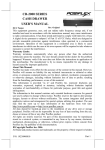
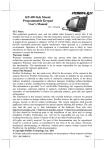
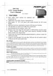
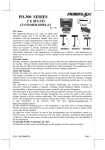
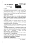
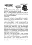
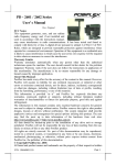
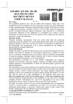
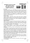
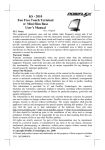
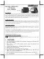
LM-2208, LM/TM-2212 LCD Monitor User’s Manual Rev. A0 FCC NOTICE This equipment generates, uses, and can radiate radio frequency energy and, if not installed and used in accordance with the instructions manual, may cause interference to radio communications. It has been tested and found to comply with limits for a Class A digital device pursuant to subpart J of Part 15 of FCC Rules, which are designed to provide reasonable protection against interference when operated in a commercial environment. Operation of this equipment in a residential area is likely to cause interference in which case the user at his own expense will be required to take whatever measures to correct the interference. WARRANTY LIMITS Warranty will terminate automatically when the machine is opened by any person other than the authorized technicians. The user should consult his/her dealer for the problem happened. Warranty voids if the user does not follow the instructions in application of this merchandise. The manufacturer is by no means responsible for any damage or hazard caused by improper application. ABOUT THIS MANUAL This manual assists the user to utilize the LCD Monitor LM-2208/LM-2212/TM-2212. These series provide adjustable robust construction for 8” LCD display with maximum resolution of 800 x 600 and 12” LCD display with maximum resolution of 1024 x 768. The manufacturer of the LM-2208/LM-2212/TM-2212 series heartily apologizes to the user for reserving the right to change or to modify this manual without notice due to the rapid and constant progress and improvement on science and technology. The user may always obtain the most up to date information through any of our web sites: http://www.posiflex.com, http://www.posiflex.com.tw, http://www.posiflexusa.com. Copyright Posiflex Technology, Inc. 2009 TRADE MARKS AND SERVICE MARKS POSIFLEX is a registered trademark of Posiflex Technology, Inc. Other brand and product names are trademarks and registered trademarks and service marks of their respective owners. I. FEATURES • The LM-2208/LM-2212/TM-2212 particularly designed for Posiflex XP series POS terminals • Most stable 8” or 12” LCD monitor with tilt adjust for industrial and commercial use • Optional side mount devices (SD300) for TM-2212 Only. • High quality TFT LCD panel • Easy maintenance structure allowing easy cleaning • Super VGA monitor resolution up to 800 x 600 pixels for LM-2208 and 1024 x 768 pixels for LM/TM-2212. • Resistive type extra long life touch panel in USB interface (for TM-2212) P/N: 19680901020 Page 1 • • Touch functions include left/right button, double click, drag & drop (for TM-2212) Support power supply through LCD cable from Posiflex XP-2000 series POS systems to operate without power adaptor II. MODEL NUMBERS LM-2208: LM-2212: TM-2212: 8” 800 x 600 LCD Monitor 12” 1024 x 768 LCD Monitor 12” 1024 x 768 LCD Touch Monitor III. CARTON CONTENTS 1. 8” or 12” LCD Monitor (Main unit assembled with Bracket) 2. User’s Manual 3. LCD Cable particular designed for LM-2208/LM-2212/TM-2212 IV. PARTS IDENTIFICATION SD-300 Main Unit Display Screen Power LED Bracket LM-2208 LM/TM-2212 LED INDICATION STATUS • Standby (no signal): Orange for LM-2208 or Green for LM/TM-2212 • Operating: Blue Control Buttons and Power switch “OSD” - OSD Menu/Submenu Engage Button “NXT” - OSD Menu/Submenu Next Button “EXT” - OSD Menu/Submenu Exit Button “+” - Up/Increase Select/Setting Button “-” - Down/Decrease Select/Set Button Power Switch LM/TM-2212 LM -2208 Page 2 V. HARDWARE INSTALLATION 2nd LCD Monitor A. Please refer to following installation and join the 2nd LCD monitor to XP2000 series step by step. 1. Cable Exit Cover Please release the cable exit cover as following steps: A: Please find the back of cable cover which just near the I/O plate. B: Please use the Fingertip to release compression lock. C: after the cable cover released, please cut the circle part which show in the picture C. A C B After finish this step, the cable cover can be use when the rear mount upgrade kits fixed. 2. Mount the bracket to XP-2000 series’ back cover Please aim to the three screws holes of bracket to the terminal’s back cover’s screws holes as show on the picture. Then fasten the screws which come with LM-2208/LM-2212/TM-2212. After fix the LM2208/LM-2212/TM-2212 to the XP-2000 series, please use the cable exit to pass through the VGA cable to the terminal’s I/O plate. Next, please use the VGA Cable to connect to the LM-2208/LM-2212/TM2212 and XP-2000 series’ VGA ports as well as use the attached USB cable to connect TM-2212 and XP-2000 series’ USB Port. After these steps, the installation process of LM-2208/LM-2212/TM-2212 is finished. For power supply of VGA ports in XP-2000 series, please contact to local dealer of authorized technicians. VGA LM-2208 USB VGA TM-2212 Page 3 B. Screws holes Winding slot Side Mount Upgrade Kit When a side-mount upgrade kit option SD-300 is ordered with the TM-2212, this option is already installed in the delivery. To assemble a separately delivered kit to the monitor, please use the 2 attached screws with washer to fix the kit to right side of LCD panel from back as the picture in the left. After fix these two screws, please route the USB cable into the winding slot. No matter the kit is SD-300 or whether the kit itself contains MSR only, finger print sensor only or both options, the kit utilizes a USB cable. Connect it to the USB port at right side of the I/O port of TM2212 and insert it in the as picture at right. USB port port VI. DRIVER INSTALLATION A. INSTALLATION USB touch The USB interface touch controller operates as an USB mouse without need for any special driver in Windows. However, there is a program supported for its calibration and touch function manipulation. Please find it in the attached Posiflex product information CD-ROM under subdirectory \Drivers\TM_LM\USB or select “Peripheral Drivers & Utilities” --> “USB Touch Manager” in version 3.0 or later of Posiflex product information CD to install it. For Linux environment, please find the setup program for the suitable kernel in the same directory and install the required driver and calibration program as the setup program proceeds. B. SETUP/CALIBRATION USB touch manager Once the USB control program is installed, the user can utilize it to calibrate the touch screen, define mouse button emulation parameters, enable right button emulation or define the click sound’s tone and duration. Please go to “Program Files” and select “Posiflex USB Touch Tools” and then select “Posiflex USB Touch Manager” within the tools to engage this utility. Most items in this utility should be easily understandable to average user. Followings are just some reminders on some items. Page 4 Calibrate – This button engages the “Posiflex USB Touch Calibrator”. Edge Acceleration – This function engages the “Posiflex USB Touch Edge Acceleration Tool” and helps to find the hidden taskbar or thin scroll bar through touch. Hide Cursor / Show Cursor – This button hides or shows the mouse cursor on screen display. Please never hide cursor before the touch is enabled and calibrated. Buzz On – This check box together with the 2 list buttons below it determines the frequency and duration of the internal buzzer beep as response to touch on touch panel. Touch Point Dots – This list button selects the size of touch point on touch panel. A too small touch size makes the mouse cursor jumpy or even bouncing. A too large touch size results in unsatisfactory touch accuracy. Reset To Default – This button resets all touch parameters. Enable PIR – This check box is not applicable to the monitor. Please keep it unchecked. Enable Touch – This check box must be checked to have the touch panel working. Touch as Right Button Click – This check box defines each touch on touch panel as clicking the right button of mouse at that point. When it is unchecked, each touch will work as clicking the left button of mouse. (Ref. to the right hand version of mouse) Mouse Emulation/Click on Touch/Click on Release – Only one of the three radio buttons can be selected. The mouse emulation refers to the drag and drop function. OK – This button accepts all parameters set and closes the utility window. Apply – This button accepts all parameters set and remains in the utility window. Cancel – This button discards all changes to the parameters and closes the utility window. USB touch calibrator This program helps re-calibrating the touch position with the USB mouse emulation. Please touch the 3 calibration boxes and a confirmation box that appear sequentially. USB touch edge acceleration tool Helps to find the hidden taskbar or thin scroll bar through touch Page 5 Enable ... – Each check box determines whether or not to engage edge acceleration against which edge of screen. Margin – This list button selects the range to engage edge acceleration toward the edge before the edge is reached. Compensation – This list button selects the distance to advance the mouse toward edge from touch point. USB touch right button tool This tool differs slightly from the “Touch as Right Button Click” check box in the USB touch manager. When executed, there will be a small window of “One Shot Right Button” appearing on desktop. Any touch on the panel right after touching this small window will work like clicking the right button of mouse at that point. However, the next touch will resume the left button of mouse unless the small window is touched again. VII. APPLICATION A. TILT ANGLE ADJUST Press down the tilt adjust release button as arrowed in the right picture and adjust the LCD panel tilt angle between 42.5° and 77.5° for best viewing effect in application and then release the button. The screen will be firmly held for operation. B. BRIGHTNESS ADJUST On lower central edge of back of the LCD panel there is a plastic wheel knob as circled in the picture above. Turn this knob up or down changes the brightness of screen display accordingly. C. APPLICATION LIMITATION The USB touch is not applicable for OS other than Windows as USB mouse is not supported in DOS environment and there is difficulty in engaging driver to convert the coordination system between the static panel and the dynamic mouse in Linux environment. D. SIDE MOUNT KIT SD-300 In SD-300 mounted at right side of the monitor, there may be the MSR for reading a magnetic stripe card and/or the optical type finger print sensor. For magnetic stripe card reading, be sure to insert the card to the bottom with magnetic stripe facing the mark aside the slot. The movement of the card can be either inserting the card from the top surface then sliding the card down out Page 6 of the slot, or sliding the card upward from the lower side of the slot till it reaches the top end as long as the card is a standard one. A non-standard card recorded without complete degaussing prior to recovery may accept only one direction in card reading. If the fingerprint sensor option is installed in the side mount kit, please find the most comfortable angle for the fingerprint taking operation in consideration of the LCD panel tilt angle and try to align the core of fingerprint in the sensing area. E. Power & OSD buttons The buttons at right side of LCD monitor are for the OSD (On Screen Display) control operations and LCD screen power control as in right picture and are explained below. “OSD” button: To enter OSD setup menu, or to perform the function selected in OSD operation. “NEXT” button: To select next item of option functions (LM/TM-2212). “EXIT” button: To Exit the option functions (LM-2208). “” “” button: To increase setting. “” “” button: To decrease setting. “” “” button: To turn the monitor power ON/OFF. The monitor can be turned OFF only when there is video signal and can be turned ON only when there is video signal and after the “Turn Off Panel” message vanishes. The default status is set to ON when power is supplied unless manually turned OFF. Since this button controls only the display power but not the display controller neither the touch controller, please try disconnect the power cable or the VGA cable once unfortunately the screen display goes into a mess. F. OSD functions Press “OSD” button with a normal display on the screen to activate the OSD functions then the OSD window will pop up on the screen. The OSD (onscreen display) is a collection of menus and controls used for adjusting the appearance and setup of monitors such as Contrast, Brightness and Colour. Please use these OSD buttons to adjust these settings. Page 7 VIII. SUPPORTED DISPLAY MODES For video signals beyond the supported display modes, there will be a message “Out Of Range” on middle of screen. Maximum supported color depth is 18 bits or 262,144 colours. Supported display modes are as in the table: Display Resolution 640*400 Refresh Rate (Hz) Horizontal Frequency (KHz) 70 31.5 60 31.5 640*480 72 37.9 75 37.5 720*400 70 31.5 56 35.1 60 37.9 800*600 72 48.1 75 46.9 60 48.4 1024*768 (Note) 70 56.5 75 60 Note: This mode applies to models marked with LM-2212 or TM-2212 only. 警告使用者 T31454 這是甲類的資訊產品,在居住的環 境中使用時,可能會造成射頻干 擾,在這種情況下,使用者會被要 求採取某些適當的對策。 Page 8