1
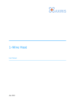
I2C 2005-1 Demonstration Board GPIO Oct, 2006 I/O Expanders Input/Output Types I/O ports selection: 4, 8,16, and 40 bits Device Output driver selection – Quasi, Totem-pole, open drain – All can sink 20 mA to 25 mA Each port programmable as input or output Bus Interface: I2C (100/400/1000kHz), SPI More features (unique for each device): - HW reset, Interrupt output, output enable - 64 I2C slave addresses (1MHz device) - Integrated EEPROM, 5-bit MUX/1-bit latch I/F Bus I/O I/O : I/O0 I/O1 I/O2 I/On #Outputs PCA9536/7 4 PCA9500/1/2 PCA9534/8 PCA9554(A) PCA9557 PCA9558 PCF8574 PCA9670/4(A) 8 8 8 8 8 8 8 PCA9535/9 PCA9555 PCF8575 PCF8575C PCA9673/5(A) 16 16 16 16 16 PCA9506 PCA9698 40 40 OD QSI IPU x x PP VCC Range x 2.3 - 5.5 x x x x x x x x x x x x x 2.3 - 5.5 2.3 - 5.5 2.3 - 5.5 2.3 - 5.5 2.3 - 5.5 x x 2.3 - 5.5 2.3 - 5.5 x x x 3.0 - 3.6 2.3 - 5.5 2.3 - 5.5 2.3 - 5.5 2.3 - 5.5 2.3 - 5.5 2.3 - 5.5 APPLICATIONS Computing Communications Consumer Medical 2 I2C 2005-1 Demonstration Board Oct, 2006 Flexible I/Os Strong PMOS on for ½ SCL VCC VCC I/O ~25 mA 100 uA Output input ~25 mA Open Drain I/O Quasi Bidirectional I/O ~10 mA R* I/O input input ~25 mA Totem-pole I/O 3 I2C 2005-1 Demonstration Board Oct, 2006 Totem Pole and Quasi-output I/O Expanders QUASI OUTPUT I/O EXPANDERS I/O: strong pull-down, weak pull-up 25 mA sink capability, no source capability Configuration register: NO Switch from output to input: I/O must be written with “1” to be used as an input Programming: Address + Data TOTEM POLE I/O EXPANDERS I/O: strong pull down, strong pull up 25 mA sink, 10 mA source capability Configuration register: YES Switch from output to input: program the configuration register accordingly Programming: Address + Command + Data 4 I2C 2005-1 Demonstration Board Oct, 2006 Demonstration Board GPIO Hardware Introduction PCA9538 RESET PCF8574 PCA9536 5 I2C 2005-1 Demonstration Board Oct, 2006 Quasi Bi-directional I/O Port Structure 6 I2C 2005-1 Demonstration Board Oct, 2006 Quasi Bi-directional I/O Port Structure 7 I2C 2005-1 Demonstration Board Oct, 2006 Exercise Objective: to understand the operation of the quasi bidirectional port structure We will use the PCF8574 interface found in Win-I2CUSB Lite Checkboxes (read-only) represent state of Port pins Checked = High Unchecked = Low Press the Read button to find the state of the IO pins P6=switch connected to ground P7=switch to Vcc P0-P3 control LEDs Checked=high (LED off) Unchecked=low (LED on) Press Write button to send data to PCF8574 or use Auto Write to send automatically 8 I2C 2005-1 Demonstration Board Oct, 2006 Exercise 1. Set all the port pins high using Win-I2CUSB Lite 2. Change the state of switch 1 on S2. 3. The INT LED should illuminate 4. Change the state of the switch. The LED should turn off. 5. Turn the INT LED again by changing the switch. 6. Using Win-I2CUSB Lite. Read the PCF8574. What happened to the Interrupt? 7. Turn the INT LED again by changing the switch. Write to the PCF8574. What happened to the Interrupt? 9 I2C 2005-1 Demonstration Board Oct, 2006 Totem Pole I/O Expanders 10 I2C 2005-1 Demonstration Board Oct, 2006 Totem-pole General Purpose IO Expanders – In a nutshell 4, 8, 16 and 40-bit Totem-pole output drivers that can sink up to 25 mA each and source up to 10 mA each 2.3 V to 5.5 V power supply with 5 V tolerant IOs Four register types allow control and monitoring of the IOs: ¾ The Configuration register defines the data direction ¾ The Output Port register controls the state of an output (‘0’ or ‘1’) ¾ The Input register reads the state of the device pin when used as input or output ¾ The Polarity Inversion register allows inversion of the pin state when reading the IOs Power-On Reset (POR) resets the state machines allowing to power up the device to a known state An active low reset pin (when available) allows to asynchronously set the device to the POR state An active low interrupt pin (when available) allows the controller to monitor a logic change in the pins that are configured as inputs 11 I2C 2005-1 Demonstration Board Oct, 2006 Totem Pole General Purpose IO Expanders – Selection Table 12 I2C 2005-1 Demonstration Board Oct, 2006 Device Hardware and Register definition Configuration Register Allows to configure the I/O as: - input when = 1 - output when = 0 Output Port Register: Allows to force an output port to 0 or 1 Totem Pole I/O structure Interrupt circuitry Polarity Inverter Register Input Port Register Polarity is retained when = 0 Polarity is inverted when = 1 13 I2C 2005-1 Demonstration Board Oct, 2006 Demonstration Board: PCA9536 Hardware Introduction Unswitched 5 V Switched 3.3 V MAIN I2C bus LEDs with different colors PCA9536: No programmable address pin I2C address = 0x82 14 I2C 2005-1 Demonstration Board Oct, 2006 Demonstration Board: PCA9536 Hardware Introduction 15 I2C 2005-1 Demonstration Board Oct, 2006 Demonstration Board: PCA9538 Hardware Introduction TO RESET PCA9543A . TO RESET PCA9551 MAIN I2C bus TO INT0 PCA9543A TO INT1 PCA9543A TO RESET PCA9531 FOR FUTURE USE FROM T_CRIT SA56004 FROM ALERT SA56004 . Active Low RESET input PCA9538 I2C address: A[1:0] = 10 Æ Address = 0xE4 Signal control and monitoring Visual status provided by LEDs 16 I2C 2005-1 Demonstration Board Oct, 2006 Demonstration Board: PCA9538 Hardware Introduction 17 I2C 2005-1 Demonstration Board Oct, 2006 Training Board: Software Introduction Device Æ LED Blinkers and Dimmers Æ PCA9531 8-bit LED Dimmer (or PCA9551 8-bit LED Blinker) I2C address: PCA9536 = 0x82 PCA9538 = 0xE4 Polarity registerallowing to invert or not the logic values read from the pins Auto Write Feature Output register programming the logic state of the pins programmed as inputs Input register reading the IOs logic states Configuration registerprogramming IOs as inputs or output 18 I2C 2005-1 Demonstration Board Oct, 2006 Hands-On 1 : PCA9536 GUI 1. Power sequence the board Æ Board OFF then ON 2. Open the PCA9536 GUI: Device Æ IO Expanders Æ PCA9536 4-bit I/O Expander 3. Switch ON the 4 LEDs connected to the PCA9536 Configuration register: the 4 I/O’s need to be configured as inputs (checked) Output register: the 4 outputs need to be forced Low 4. Uncheck C0, C1, C2 and C3 Check O0 and O1 in the Output Register (O2 and O3 unchecked) Check N0 and N2 in the Polarity Register (N1 and N3 unchecked) Read the Input Register and explain what you see I0 = I1 = I2 = I3 = Low High High Low Æ Inverted Logic state of I/O0 Æ Logic state of I/O1 Æ Inverted Logic state of I/O2 Æ Logic state of I/O3 19 I2C 2005-1 Demonstration Board Oct, 2006 Hands-On 2: Using the Expert Mode Write the following I2C sequence (Red) using the Expert Mode 1. Power sequence the board Æ Board OFF then ON 2. Program PCA9538 I/O0 to I/O4 as output (and be sure that I/O5 to I/O7 are configured as inputs) 3. Switch ON PCA9538 I/O0 only and wait 0.5 s 4. Switch ON PCA9538 I/O1 only and wait 0.5 s 5. Switch ON PCA9538 I/O2 only and wait 0.5 s 6. Switch ON PCA9538 I/O3 only and wait 0.5 s 7. Switch ON PCA9538 I/O4 only and wait 0.5 s Execute it in loop 20 I2C 2005-1 Demonstration Board Oct, 2006 Hands-On 2: Using the Expert Mode – Solution 21 I2C 2005-1 Demonstration Board Oct, 2006