1
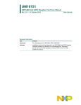
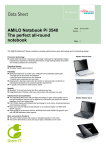
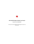
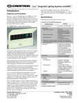
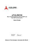
UM10752 OM13489 16-bit GPIO Daughter Card User Manual Rev. 2.0 — 09 January 2014 User manual Document information Info Content Keywords Fm+ Development Kit, OM13320, GPIO, OM13303 Abstract Installation guide and User Manual for the OM13489 16-bit GPIO Daughter Card that connects to OM13320 Fm+ Development Kit. This 2 board permits easy and simple evaluation of most of NXP’s 16-bit I C GPIO portfolio of products. UM10752 NXP Semiconductors OM13489 16-bit GPIO User Manual Revision history Rev Date Description 2.0 20140109 Added A0 jumper hardware fix and CN5 schematic – changed from 14-pin to 18-pin with 4 pins not connected for correct connector seating on the Fm+ board. Active pins remain the same. Labels for JP7 and JP8 (A1 and A2 address jumpers) are incorrect; 1 connects to ground and 0 connects to VDDP 1.0 20131011 Initial Release Contact information For more information, please visit: http://www.nxp.com For sales office addresses, please send an email to: [email protected] UM10752 User manual All information provided in this document is subject to legal disclaimers. Rev. 2.0 — 09 January 2014 © NXP B.V. 2014. All rights reserved. 2 of 16 UM10752 NXP Semiconductors OM13489 16-bit GPIO User Manual 1. Introduction 2 The OM13489 16-bit I C GPIO Daughter Card connects to the OM13320 Fm+ Development 2 kit and permits easy evaluation of most of NXP’s 16-bit I C GPIO portfolio of products. Table_1 lists the supported devices. 2 The OM13489 16-bit I C GPIO Daughter Card is shipped with no GPIO device soldered to the board. The user must purchase the device he is interested in evaluating in a TSSOP24 package (the ordering part number suffix should be “PW” and the package designation should be SOT355-1). These leaded packages should be relatively easy to solder to the board with a low wattage, fine tipped soldering iron. NOTE pin 1 orientation pointing toward C1. Please note that a fix is needed for correct operation of the A0 jumper JP1. A wire must be soldered between pin 2 of JP1 and the via directly below to make connection to pin 21 on the device under test IC1. See Section 3.2 for additional details. Table 1. Device PCA6416A PCA8575 PCA9535A PCA9535C PCA9535 PCA9539A PCA9539 PCA9539R PCA9555A PCA9555 PCA9671 PCA9673 PCA9675 PCAL6416A PCAL9535A PCAL9539A PCAL9555A PCF8575 UM10752 User manual 2 Devices Supported by OM13489 16-bit I C GPIO Daughter Card Description Orderable Part Number Low-voltage translating 16-bit I²C-bus/SMBus I/O expander with interrupt output, reset, and configuration registers 2 Remote 16-bit I/O expander for I C-bus with interrupt Low-voltage 16-bit I²C-bus I/O port with interrupt 2 16-bit I C-bus and SMBus, low power I/O port with interrupt 2 16-bit I C-bus and SMBus, low power I/O port with interrupt Low voltage 16-bit I²C-bus I/O port with interrupt and reset 16-bit I²C-bus and SMBus low power I/O port with interrupt and reset 16-bit I²C-bus and SMBus low power I/O port with interrupt and reset Low-voltage 16-bit I²C-bus I/O port with interrupt and weak pull-up 2 16-bit I C-bus and SMBus I/O port with interrupt 2 Remote 16-bit I/O expander for Fm+ I C-bus with reset 2 Remote 16-bit I/O expander for Fm+ I C-bus with interrupt and reset 2 Remote 16-bit I/O expander for Fm+ I C-bus with interrupt Low-voltage translating 16-bit I²C-bus/SMBus I/O expander with interrupt output, reset, and configuration registers Low-voltage 16-bit I²C-bus I/O port with interrupt and Agile I/O Low-voltage 16-bit I²C-bus and SMBus low power I/O port with interrupt and reset Low-voltage 16-bit I²C-bus GPIO with Agile I/O, interrupt and weak pull-up 2 Remote 16-bit I/O expander for I C-bus All information provided in this document is subject to legal disclaimers. Rev. 2.0 — 09 January 2014 PCA6416APW PCA8575PW PCA9535APW PCA9535CPW PCA9535PW PCA9539APW PCA9539PW PCA9539RPW PCA9555APW PCA9555PW PCA9671PW PCA9673PW PCA9675PW PCAL6416APW PCAL9535APW PCAL9539APW PCAL9555APW PCF8575PW © NXP B.V. 2014. All rights reserved. 3 of 16 UM10752 NXP Semiconductors OM13489 16-bit GPIO User Manual The pin configuration of these devices varies only a bit and the different pin selections are made via jumpers. 2. Features of the OM13489 16-bit GPIO Daughter Card Direct connection to OM13320 Fm+ Development kit Footprint for a TSSOP24 package, user solderable Jumper configuration accommodates most NXP 16-bit GPIO Flexible power supply configuration: 3.3V, 5V or external supply Direct connection to OM13303 GPIO Target board for I/O visualization 2 Jumper configuration of device I C address LED indicators for power and INT Scope ground connection loop 3. Pin Configuration of 16-bit GPIO Devices 1 24 VCC(P) 2 23 SDA 3 22 SCL P0_0 4 21 ADDR P0_1 5 20 P1_7 P0_2 6 19 P1_6 P0_3 7 18 P1_5 P0_4 8 17 P1_4 P0_5 9 16 P1_3 P0_6 10 15 P1_2 P0_7 11 14 P1_1 VSS 12 13 P1_0 A1 VCC(I2C-bus ) RESET A2 PCA9671 PCA(L)9535/55 PCA8575 PCA9675 PCF8575 PCA(L)9539 PCA9673 PCA(L)6416 O INT RESET Fig 1. PCA(L)6416 PCA(L)9539 PCA9673 PCA(L)9535/55 PCA8575 PCA9675 PCF8575 PCA9671 The different 16-bit GPIO devices pin configurations differ only slightly between devices. See Fig 1 for a description of the different pinouts. Pin Configuration 16-bit GPIO Devices UM10752 User manual All information provided in this document is subject to legal disclaimers. Rev. 2.0 — 09 January 2014 © NXP B.V. 2014. All rights reserved. 4 of 16 UM10752 NXP Semiconductors OM13489 16-bit GPIO User Manual 3.1 Power Supply Setup Power supply voltages may be selected from the tester connector CN4 or the Fm+ board CN5. If one selects Fm+ CN5, either 3.3V or 5V can be chosen. Additionally, the PCA(L)6416 device implements two power supplies which are separately chosen, i.e. one can be 3.3V and the other 5V for voltage level translation evaluation. Both of these power supplies can be supplied externally by using TP1 and TP2 near the tester connector CN4. See the schematic section at the end of this document for more details. The jumpers for power supply selection are CN3, JP3, and JP4 3.2 Reset, Interrupt, and Address pins selection The Reset, Interrupt and Address pins are used in combinations on various devices. The selection matrix on the 16-bit GPIO board sends pins 1, 2, and 3 to determine if the pins are address or function on JP9, JP10, and JP11. Then, if they are determined address pins, JP1, JP7 and JP8 tie them to logic high or low. If they are determined to be function pins, the other position of JP9, JP10 and JP11 tie them to the correct connector function pins. See the schematic section at the end of this document for more details. The logic high level for the address pins is VDDP . Please note that a fix is needed for correct operation of the A0 jumper JP1. A wire must be soldered between pin 2 of JP1 and the via directly below to make connection to pin 21 on the device under test IC1. Use 30 AWG wire wrap wire for the easiest connection. The solder mask on the board will prevent any short circuits. Please note that A1 and A2 jumpers are incorrectly labeled. JP7 and JP8 program I2C addresses when selected. The labels show that A1 and A2 pins will be connected to ground when the jumper shorts pin 1 and 2 (toward the bottom edge of the board). In fact, this is a connection to VDDP or high. The schematic is correct, only the labels are incorrect. Fig 2. Fix needed for correct operation of A0 jumper JP1 4. Board Jumper Set Up 4.1 Power Supply Jumpers The power supply selections for the OM13489 is very flexible and allows for detailed analysis and evaluation of all the NXP 16-bit GPIO devices. JP3 labeled PWR selects between 5V supplied from the tester connector CN4 (jumper between pin 2 and 3 labeled TSTR) and the Fm+ board connector CN5 (jumper between pin 1 and 2). If 3.3V or external power operation is desired, no jumper is required. UM10752 User manual All information provided in this document is subject to legal disclaimers. Rev. 2.0 — 09 January 2014 © NXP B.V. 2014. All rights reserved. 5 of 16 UM10752 NXP Semiconductors OM13489 16-bit GPIO User Manual CN3 selects between 5V and 3.3V for a second power supply needed for PCA(L)6408A. If the device under test is not PCA(L)6408A, leave this jumper open. JP4 selects between 5V and 3.3V for the main power supply on pin 16 of the device under test. Add a jumper between pins 2 & 3 for 3.3V or 1 & 2 for 5V. For external power supply operation, do not jumper CN3, JP3 and JP4 and connect a voltage source to TP2 for the main power supply connected to pin 16 of the device under test. Connect another external voltage source to TP1 if the device under test is PCA(L)6408A. See the schematic section at the end of this document for more details. Fig 3. Power Jumpers and External Power Test Points 4.2 SCL and SDA Jumpers The I2C-bus signals SDA and SCL supplied to the device under test can be sourced from either the Fm+ board via CN5 or the tester via CN4. Jumpers JP5 and JP6 select the source. Shorting pins 1 to 2 source from the Fm+ board while shorting pins 2 to 3 source from the tester connector CN4. See the schematic section at the end of this document for more details. Fig 4. SDA and SCL Jumpers 4.3 PCA8575, PCA9535A, PCA9535C, PCA9535, PCA9555A, PCA9555, PCA9675, PCAL9535A, PCAL9555A, PCF8575 The PCA8575, PCA9535/A/C, PCA9555/A, PCA9675 and PCF8575 series implement three address pins and INT . This configuration ignores the power supply setup, but normally, only JP4 with a jumper between pins 2 & 3 need be applied to power the device at 3.3V. UM10752 User manual All information provided in this document is subject to legal disclaimers. Rev. 2.0 — 09 January 2014 © NXP B.V. 2014. All rights reserved. 6 of 16 UM10752 NXP Semiconductors OM13489 16-bit GPIO User Manual To configure the function pins, apply jumpers between pins 1 & 2 on JP10 and JP11 to configure device pin 2 and pin 3 as addresses. Apply a jumper between pins 2 & 3 on JP9 to configure device pin 1 as INT . 2 Then, apply jumpers to JP1, JP7 and JP8 to configure the desired I C address. Logic high or logic low is labeled on the board, but is incorrect for JP7 and JP8. Using the labels, a 0 is actually a 1 and a labeled 1 is actually a 0. The schematic is correct and note the square solder pad is pin 1. Fig 5. Jumper Configuration for PCA8575, PCA9535A, PCA9535C, PCA9535, PCA9555A, PCA9555, PCA9675, PCAL9535A, PCAL9555A, PCF8575 4.4 PCA9671 The PCA9671 implements three address pins and RST . This configuration ignores the power supply setup, but normally, only JP4 with a jumper between pins 2 & 3 need be applied to power the device at 3.3V. To configure the function pins, apply jumpers between pins 1 & 2 on JP9, JP10 and JP11 to configure pin 2 and pin 3 as addresses and pin 1 as RST . 2 Then, apply jumpers to JP1, JP7 and JP8 to configure the desired I C address. Logic high or logic low is labeled on the board, but is incorrect for JP7 and JP8. Using the labels, a 0 is actually a 1 and a labeled 1 is actually a 0. The schematic is correct and note the square solder pad is pin 1. Fig 6. UM10752 User manual Jumper Configuration for PCA9671 All information provided in this document is subject to legal disclaimers. Rev. 2.0 — 09 January 2014 © NXP B.V. 2014. All rights reserved. 7 of 16 UM10752 NXP Semiconductors OM13489 16-bit GPIO User Manual 4.5 PCA9673, PCAL9539A, PCA9539A, PCA9539R, PCA9539 The PCA9673 and PCA9539 series implement two address pins, RST and INT . This configuration ignores the power supply setup, but normally, only JP4 with a jumper between pins 2 & 3 need be applied to power the device at 3.3V. To configure the function pins, apply jumpers between pins 2 & 3 on JP9 and JP11 to configure device pin 3 as RST and device pin 1 as INT . Apply a jumper between pins 1 & 2 on JP10 to configure device pin 2 as an address. 2 Then, apply jumpers to JP1 and JP7 to configure the desired I C address. Logic high or logic low are labeled on the board. Leave JP8 open. The labels are incorrect for JP7 and JP8. Using the labels, a 0 is actually a 1 and a labeled 1 is actually a 0. The schematic is correct and note the square solder pad is pin 1. Fig 7. Jumper Configuration for PCA9673, PCAL9539A, PCA9539A, PCA9539R, PCA9539 4.6 PCAL6416A, PCA6416A The PCA(L)6416A devices are level translating, Agile I/0 Expanders with two power supplies, one address pin, RST and INT . The two power supplies may operate at different voltages 2 to translate from the I C-bus voltage domain to a higher or lower I/O voltage. CN3 and JP4 may be set to the same or different voltages, or left open and external voltage sources connected to TP1 and TP2. See the datasheet for more details on voltage level translation. Note that the 10K pull up resistors SDA and SCL, R5 and R6, are connected to VDDP which may cause incorrect current readings if two different supplies are used. To configure the function pins, apply jumpers between pins 2 & 3 on JP9, J10 and JP11 to configure device pin 2 as a power supply, device pin 3 as RST and device pin 1 as INT . 2 Then, apply a jumper to JP1 to configure the desired I C address. Logic high or logic low are labeled on the board. Leave JP7 and JP8 open. UM10752 User manual All information provided in this document is subject to legal disclaimers. Rev. 2.0 — 09 January 2014 © NXP B.V. 2014. All rights reserved. 8 of 16 UM10752 NXP Semiconductors OM13489 16-bit GPIO User Manual Fig 8. Jumper Configuration for PCA(L)6416 5. Connector Pinouts 5.1 CN1 GPIO Target Board Connector The OM13303 GPIO Target Board consists of eight LEDs and eight switches and connects directly to the 16-bit GPIO board through CN1. The switches and LEDs permit easy exercise of the I/O functionality of the device under test. The LEDs light red when the voltage on that channel is below VCC x 0.3V and lights green when the voltage is above VCC x 0.7V. The LEDs remain off when the voltage is between those two levels. Table 2. CN1 GPIO Target Board Connector Pinout CN1 Pin Number Function Board Connection 1 VDD VDDP 2 Ground GND 3 IO0 U1 pin 4 4 IO1 5 IO2 6 IO3 7 IO4 8 IO5 9 IO6 10 IO7 U1 pin 5 U1 pin 6 U1 pin 7 U1 pin 9 U1 pin 10 U1 pin 11 U1 pin 12 5.2 CN5 Fm+ Development Board Connector The OM13489 can connect directly to the OM13320 Fm+ Development kit via CN5. This 2 connector provides power, I C signals and other ancillary signals. Note: The connector on the Fm+ board is a male, shrouded 14 pin type, while the connector on the GPIO board is female, 18 pin.. The reason lies with the shroud around the 14 pin connector. To ensure correct mating of the female with the male, two pin positions on both of the female sides are unused. UM10752 User manual All information provided in this document is subject to legal disclaimers. Rev. 2.0 — 09 January 2014 © NXP B.V. 2014. All rights reserved. 9 of 16 UM10752 NXP Semiconductors OM13489 16-bit GPIO User Manual Table 3. CN5 Fm+ Board Connector CN5 Pin Number Function Board Connection 1 — No connect 2 — No connect 3 SCL 4 SDA2 5 INT 6 RESET 7 +5V 8 +3.3V 9 GND 10 GND 11 +3.3V 12 +5V 13 RESET 14 INT 15 SDA 16 SCL2 17 — 18 — SCL Bus 1 to U1 pin 14 SDA Bus 2 not used Interrupt to INT LED and JP9 pin 3 JP9 pin 1, JP11 pin 3 JP3 pin 1 CN3 pin 3 and JP4 pin 3 CN3 pin 3 and JP4 pin 3 JP3 pin 1 JP9 pin 1, JP11 pin 3 Interrupt to INT LED and JP9 pin 3 SDA Bus 1 to U1 pin 15 SCL Bus 2 not used No connect No connect 5.3 CN4 Tester Connector 2 Generation, inspection and logging of I C-Bus data is easily achieved with third party development tools from Total Phase (www.totalphase.com) There are two tools called Aardvark and Beagle that direct connect to this board through CN4. Note: Since SDA and SCL are both connected to the device under test, the Aardvark and the Fm+ Development board cannot be used simultaneously. The Beagle, a bus sniffer, does not have any issues. Table 4. CN4 Tester Connector CN4 Pin Number Function UM10752 User manual Board Connection 1 SCL U1 pin 14 2 Ground 3 SDA U1 pin 15 4 +5V 5 +5V 6 +5V JP3 pin 3 JP3 pin 3 JP3 pin 3 7 — 8 — 9 — 10 Ground All information provided in this document is subject to legal disclaimers. Rev. 2.0 — 09 January 2014 © NXP B.V. 2014. All rights reserved. 10 of 16 NXP Semiconductors UM10752 User manual Rev. 2.0 — 09 January 2014 All information provided in this document is subject to legal disclaimers. UM10752 OM13489 16-bit GPIO User Manual 11 of 16 © NXP B.V. 2014. All rights reserved. NXP Semiconductors UM10752 User manual Rev. 2.0 — 09 January 2014 All information provided in this document is subject to legal disclaimers. UM10752 OM13489 16-bit GPIO User Manual 12 of 16 © NXP B.V. 2014. All rights reserved. UM10752 NXP Semiconductors OM13489 16-bit GPIO User Manual 6. Legal information 6.1 Definitions Draft — The document is a draft version only. The content is still under internal review and subject to formal approval, which may result in modifications or additions. NXP Semiconductors does not give any representations or warranties as to the accuracy or completeness of information included herein and shall have no liability for the consequences of use of such information. 6.2 Disclaimers Limited warranty and liability — Information in this document is believed to be accurate and reliable. However, NXP Semiconductors does not give any representations or warranties, expressed or implied, as to the accuracy or completeness of such information and shall have no liability for the consequences of use of such information. In no event shall NXP Semiconductors be liable for any indirect, incidental, punitive, special or consequential damages (including - without limitation - lost profits, lost savings, business interruption, costs related to the removal or replacement of any products or rework charges) whether or not such damages are based on tort (including negligence), warranty, breach of contract or any other legal theory. Evaluation products — This product is provided on an “as is” and “with all faults” basis for evaluation purposes only. NXP Semiconductors, its affiliates and their suppliers expressly disclaim all warranties, whether express, implied or statutory, including but not limited to the implied warranties of noninfringement, merchantability and fitness for a particular purpose. The entire risk as to the quality, or arising out of the use or performance, of this product remains with customer. In no event shall NXP Semiconductors, its affiliates or their suppliers be liable to customer for any special, indirect, consequential, punitive or incidental damages (including without limitation damages for loss of business, business interruption, loss of use, loss of data or information, and the like) arising out the use of or inability to use the product, whether or not based on tort (including negligence), strict liability, breach of contract, breach of warranty or any other theory, even if advised of the possibility of such damages. Notwithstanding any damages that customer might incur for any reason whatsoever (including without limitation, all damages referenced above and all direct or general damages), the entire liability of NXP Semiconductors, its affiliates and their suppliers and customer’s exclusive remedy for all of the foregoing shall be limited to actual damages incurred by customer based on reasonable reliance up to the greater of the amount actually paid by customer for the product or five dollars (US$5.00). The foregoing limitations, exclusions and disclaimers shall apply to the maximum extent permitted by applicable law, even if any remedy fails of its essential purpose. Notwithstanding any damages that customer might incur for any reason whatsoever, NXP Semiconductors’ aggregate and cumulative liability towards customer for the products described herein shall be limited in accordance with the Terms and conditions of commercial sale of NXP Semiconductors. Right to make changes — NXP Semiconductors reserves the right to make changes to information published in this document, including without limitation specifications and product descriptions, at any time and without notice. This document supersedes and replaces all information supplied prior to the publication hereof. Suitability for use — NXP Semiconductors products are not designed, authorized or warranted to be suitable for use in life support, life-critical or safety-critical systems or equipment, nor in applications where failure or malfunction of an NXP Semiconductors product can reasonably be expected to result in personal injury, death or severe property or environmental damage. NXP Semiconductors accepts no liability for inclusion and/or use of NXP Semiconductors products in such equipment or applications and therefore such inclusion and/or use is at the customer’s own risk. Applications — Applications that are described herein for any of these products are for illustrative purposes only. NXP Semiconductors makes no representation or warranty that such applications will be suitable for the specified use without further testing or modification. Customers are responsible for the design and operation of their applications and products using NXP Semiconductors products, and NXP Semiconductors accepts no liability for any assistance with applications or customer product design. It is customer’s sole responsibility to determine whether the NXP Semiconductors product is suitable and fit for the customer’s applications and products planned, as well as for the planned application and use of customer’s third party customer(s). Customers should provide appropriate design and operating safeguards to minimize the risks associated with their applications and products. NXP Semiconductors does not accept any liability related to any default, damage, costs or problem which is based on any weakness or default in the customer’s applications or products, or the application or use by customer’s third party customer(s). Customer is responsible for doing all necessary testing for the customer’s applications and products using NXP Semiconductors products in order to avoid a default of the applications and the products or of the application or use by customer’s third party customer(s). NXP does not accept any liability in this respect. Export control — This document as well as the item(s) described herein may be subject to export control regulations. Export might require a prior authorization from competent authorities. UM10752 User manual All information provided in this document is subject to legal disclaimers. Rev. 2.0 — 09 January 2014 © NXP B.V. 2014. All rights reserved. 13 of 16 UM10752 NXP Semiconductors OM13489 16-bit GPIO User Manual 7. List of figures Fig 1. Fig 2. Fig 3. Fig 4. Fig 5. Fig 6. Fig 7. Fig 8. Pin Configuration 16-bit GPIO Devices ............. 4 Fix needed for correct operation of A0 jumper JP1 .......................................................................... 5 Power Jumpers and External Power Test Points6 SDA and SCL Jumpers ..................................... 6 Jumper Configuration for PCA8575, PCA9535A, PCA9535C, PCA9535, PCA9555A, PCA9555, PCA9675, PCAL9535A, PCAL9555A, PCF85757 Jumper Configuration for PCA9671 .................. 7 Jumper Configuration for PCA9673, PCAL9539A, PCA9539A, PCA9539R, PCA9539 ................... 8 Jumper Configuration for PCA(L)6416 .............. 9 UM10752 User manual All information provided in this document is subject to legal disclaimers. Rev. 2.0 — 09 January 2014 © NXP B.V. 2014. All rights reserved. 14 of 16 UM10752 NXP Semiconductors OM13489 16-bit GPIO User Manual 8. List of tables Table 1. Table 2. Table 3. Table 4. 2 Devices Supported by OM13489 16-bit I C GPIO Daughter Card .................................................. 3 CN1 GPIO Target Board Connector Pinout ...... 9 CN5 Fm+ Board Connector ............................ 10 CN4 Tester Connector .................................... 10 UM10752 User manual All information provided in this document is subject to legal disclaimers. Rev. 2.0 — 09 January 2014 © NXP B.V. 2014. All rights reserved. 15 of 16 UM10752 NXP Semiconductors OM13489 16-bit GPIO User Manual 9. Contents 1. 2. 3. 3.1 3.2 4. 4.1 4.2 4.3 4.4 4.5 4.6 5. 5.1 5.2 5.3 6. 6.1 6.2 7. 8. 9. Introduction ......................................................... 3 Features of the OM13489 16-bit GPIO Daughter Card ...................................................................... 4 Pin Configuration of 16-bit GPIO Devices ......... 4 Power Supply Setup........................................... 5 Reset, Interrupt, and Address pins selection ...... 5 Board Jumper Set Up.......................................... 5 Power Supply Jumpers ...................................... 5 SCL and SDA Jumpers ...................................... 6 PCA8575, PCA9535A, PCA9535C, PCA9535, PCA9555A, PCA9555, PCA9675, PCAL9535A, PCAL9555A, PCF8575 ...................................... 6 PCA9671 ............................................................ 7 PCA9673, PCAL9539A, PCA9539A, PCA9539R, PCA9539 ............................................................ 8 PCAL6416A, PCA6416A.................................... 8 Connector Pinouts .............................................. 9 CN1 GPIO Target Board Connector................... 9 CN5 Fm+ Development Board Connector.......... 9 CN4 Tester Connector ..................................... 10 Legal information .............................................. 13 Definitions ........................................................ 13 Disclaimers....................................................... 13 List of figures..................................................... 14 List of tables ...................................................... 15 Contents ............................................................. 16 Please be aware that important notices concerning this document and the product(s) described herein, have been included in the section 'Legal information'. © NXP B.V. 2014. All rights reserved. For more information, please visit: http://www.nxp.com For sales office addresses, please send an email to: [email protected] Date of release: 09 January 2014 Document identifier: UM10752