1
Automated Test Design™
Designer 4.4
User Manual
Copyright © Conformiq Inc. and its subsidiaries . All Rights Reserved.
Unauthorized reproduction prohibited. Conformiq and Conformiq Designer are
trademarks of Conformiq Inc. and its subsidiaries. Some other trademarks belong to
their respective owners.
Conformiq User Manual
Copyright (C) Conformiq Software Oy and its subsidiaries 1998-2011. All Rights Reserved. All information may be
subject to change without notice.
For more information about Conformiq Software and its products, please go to http://www.conformiq.com/.
Conformiq, Conformiq Designer and Conformiq Modeler are trademarks of Conformiq Software Oy. Java is a
trademark of Sun Microsystems. UML is a trademark of the Object Management Group. Other trademarks
appearing in the text belong to their respective owners.
iii
Table of Contents
1
Introduction
12
1.1
1.2
1.3
1.4
The Design-Validation Cycle
Costs of Testing
Conformiq in Software Process
Benefits of Conformiq
13
14
16
17
2
Installing Conformiq
19
2.1
System Requirements
Conformiq Eclipse Client Requirements
Conformiq Computation Server Requirements
Other Requirements
Preparations
Notes on Migrating to 4.3 Release
Installing Conformiq on Windows
How to Install Conformiq on Windows
How to Uninstall Conformiq on Windows
Installing Conformiq on Linux
How to Install Conformiq on Linux
How to Uninstall Conformiq on Linux
Checking the QEC Installation
License Management in Conformiq
Configuring Conformiq Feature Set
Conformiq Evaluation
Named User Licensing
Floating Licensing
Obtaining Node Identifiers
License Server Management
Flexera based license server
Web-based license server
20
20
21
21
22
22
23
23
26
26
26
28
29
31
32
33
34
35
38
38
39
39
2.1.1
2.1.2
2.1.3
2.2
2.3
2.4
2.4.1
2.4.2
2.5
2.5.1
2.5.2
2.6
2.7
2.7.1
2.7.2
2.7.3
2.7.4
2.7.5
2.8
2.8.1
2.8.2
iv
3
3.1
3.2
3.3
3.4
3.5
3.6
3.7
3.8
User Manual
Testing with Conformiq
42
Quick Start of Using Conformiq
43
Deploying Example Conformiq Projects
44
How to Switch to Conformiq Perspective
47
How to Configure Conformiq Eclipse Client
47
How to Work with Conformiq Projects
50
How to Select Models
54
How to Create Test Design Configurations
57
How to Create Use Cases
58
3.8.1
Why Create a Use Case
59
3.8.2
Basic Features of a Use Case
61
3.8.3
Defining a Use Case
63
3.8.4
Updating a Use Case
65
3.9
How to Configure Test Generation
66
3.9.1
How to Configure Global Testing Parameters
66
3.9.2
How to Configure Design Configuration Specific Testing Parameters 72
3.10
How to Generate Tests
79
3.10.1
Test Case Selection in Conformiq
80
3.10.2
Perturbation
82
3.10.3
Test Generation Time Warnings
85
3.10.4
Model Profiler
88
3.10.5
Intelligent Test Case Naming
91
3.11
How to Analyze Test Generation Results
94
3.11.1
Coverage Editor
96
3.11.2
Test Case List
97
3.11.3
Traceability Matrix View
99
3.11.4
Test Dependency Matrix
100
3.11.5
Test Case View
102
3.11.6
Test Step View
104
3.11.7
Model Browser
105
3.11.8
Execution Trace View
108
v
3.11.9
Analyzing Model Defects
How to Export Test Cases
3.12.1
How to Use Scripters from Scripter Warehouse
3.12.2
How to Use Script Backends Shipped with Conformiq
3.13
Test Case Management
3.14
Managing Conformiq Projects
3.15
Command Line User Interface
3.12
4
4.1
4.2
4.3
109
124
128
131
148
151
152
Creating Models in QML
157
Textual Notation of QML
Basic Language Features
4.2.1
Keywords
4.2.2
Comments
4.2.3
Literals
4.2.4
Operators
4.2.5
Data Types
4.2.6
Access Modifiers
4.2.7
Type Aliases
4.2.8
Control structures
4.2.9
Input and Output
4.2.10
System Block
4.2.11
Main Entry Point
4.2.12
Globals and Functions
4.2.13
Modifiers
Object Orientation
4.3.1
Inheritance
4.3.2
Interfaces
4.3.3
Operator Overloading
4.3.4
Templates
4.3.5
Nullable Types
4.3.6
Implicitly Typed Local Variables
158
159
160
164
164
165
167
183
183
184
186
188
189
189
190
190
190
191
191
192
194
195
vi
User Manual
4.4
4.4.1
4.4.2
4.4.3
4.4.4
4.5
4.5.1
4.5.2
4.5.3
4.5.4
4.5.5
4.6
4.6.1
4.6.2
4.6.3
4.6.4
4.6.5
4.6.6
4.6.7
4.7
4.7.1
4.7.2
4.7.3
4.7.4
4.7.5
4.8
4.8.1
4.8.2
4.8.3
4.9
4.9.1
Modeling for Test Generation
Modeling Combinatorial Test Data
Model Regions
Regions with No Coverage Goals
Scenario and Narrative
Predefined Data Types
Class and Record Super Types
Threads and Communication
Exceptions
Synchronization
Containers
Predefined Functions
Assertion Like Functions
Query Functions for Fields of Structured Types
Requirements
Mathematical Functions
Probabilities and Priorities
End Conditions for Test Generation
Miscellaneous Functions
Graphical Notation of QML
State Machines
Transition Strings
Internal Transitions of a State
Entry and Exit Actions
Including State Charts
Examples
A Simple Echo Model
Another Echo Model
Yet Another Echo Model
Importing TTCN-3 Type Definitions Into Conformiq
Introduction
197
197
199
201
202
203
203
203
206
207
208
212
213
214
215
216
217
219
221
222
222
224
227
228
229
231
231
231
233
235
235
vii
4.9.2
4.9.3
4.9.4
4.9.5
4.9.6
4.9.7
4.9.8
4.9.9
4.9.10
How to Include TTCN Files in a Conformiq Project
Basic types
Record, Set and Union Types
List Types
Enumerated Types
Aliasing
Constants
Special types
Summary of TTCN-3 limitations
236
237
242
243
243
244
244
245
245
5
Using Conformiq Modeler
246
5.1
5.2
5.3
5.4
5.5
Opening a model
Saving a model
State machines
Drawing
Zooming
Scrolling
States
Transitions
Notes and note connectors
Undo and Redo
248
249
249
249
250
250
250
251
251
252
6
Importing Models from Third Party Tools
6.1
Enterprise Architect
Imported Components
Project Layout
Declaring State Machines
Defining Transitions
States
QML Tagged Comments
System Block
5.4.1
5.4.2
5.4.3
5.4.4
5.4.5
6.1.1
6.1.2
6.1.3
6.1.4
6.1.5
6.1.6
6.1.7
253
254
255
255
256
256
257
259
259
viii
User Manual
6.1.8
6.1.9
6.1.10
6.1.11
6.1.12
6.3
Main Entry Point
Records
Exporting from Enterprise Architect
Importing into Conformiq
Components not Imported
Rhapsody System Designer
Imported Components
Example Echo Model
Example Echo Model in Rhapsody
Summary
Rational Software Architect
7
Test and Requirement Management Tool Integrations
7.1
7.2
Configuring a Test / Requirement Management Tool Integration
HP Quality Center Integration
Annotating the Model with Requirements
Configuring the HP Quality Center Connection
IBM Rational RequisitePro Integration
Annotating the Model with Requirements
Configuring the IBM Rational RequisitePro Connection
IBM Rational DOORS Integration
Annotating the Model with Requirements
Configuring the IBM Rational DOORS Connection
6.2
6.2.1
6.2.2
6.2.3
6.2.4
7.2.1
7.2.2
7.3
7.3.1
7.3.2
7.4
7.4.1
7.4.2
8
Creating Conformiq Scripting Backends
8.1
8.2
8.3
8.4
8.5
8.6
Communicating Using QML Datum Interface
Creating Scripting Backends in Java
Exposing Scripting Backend Configuration
Preparing Eclipse Workbench
Creating Java Project for Scripting Backends
Creating Scripting Backend JAR
260
260
262
262
263
263
263
265
268
275
275
285
287
289
291
292
294
294
295
295
296
297
299
300
301
312
315
315
317
ix
8.7
Debugging Scripting Backends
9
Support and Troubleshooting
9.1
9.2
Troubleshooting Guidelines
Troubleshooting QEC
Performance Problems
Reporting Problems with Conformiq
A
Conformiq Release Notes
A.1
A.2
Download and Install
Conformiq 4.4.2
What's New or Changed
Conformiq 4.4.1
What's New or Changed
Conformiq 4.4.0
Use Case Support
Perturbation (Generation of Non Standard Data Distribution)
Intelligent Test Case Naming
Improved Detection of Parsing Errors
Command Line Interface for Batch Mode Execution
Other New Features
Other Updates
Known Problems
Conformiq 4.3.1
Conformiq 4.3.0
Model Debugger
Support for Flexera Publisher Based Licenses
Internal Database Migration from PostgreSQL to SQLite
Support for Temporarily Increasing the Search Depth
Support for Including State Charts
Experimental Support for Model Regions
9.1.1
9.1.2
A.2.1
A.3
A.3.1
A.4
A.4.1
A.4.2
A.4.3
A.4.4
A.4.5
A.4.6
A.4.7
A.4.8
A.5
A.6
A.6.1
A.6.2
A.6.3
A.6.4
A.6.5
A.6.6
318
319
320
320
322
323
325
326
327
327
331
331
334
335
335
336
336
336
336
337
338
341
342
342
342
343
343
343
344
x
User Manual
A.7
A.8
A.9
A.10
A.11
A.12
A.13
A.14
A.15
A.16
Conformiq 4.2.2
Conformiq 4.2.1
Conformiq 4.2.0
Qtronic 2.1.2
Qtronic 2.1.1
Qtronic 2.1.0
Qtronic 2.0.3
Qtronic 2.0.2
Qtronic 2.0.1
Qtronic 2.0.0
B
Plugin API Reference Manual
com.conformiq.qtronic2.QMLValue Interface
com.conformiq.qtronic2.QMLTypeVisitor Interface
com.conformiq.qtronic2.Checkpoint Interface
com.conformiq.qtronic2.QMLRecordType Interface
com.conformiq.qtronic2.QMLNumber Interface
com.conformiq.qtronic2.Plugin Class
com.conformiq.qtronic2.QMLOptional Interface
com.conformiq.qtronic2.TimeStamp Class
com.conformiq.qtronic2.Checkpoint.CheckpointStatus Class
com.conformiq.qtronic2.QMLArrayType Interface
com.conformiq.qtronic2.QMLUnion Interface
com.conformiq.qtronic2.QMLRecord Interface
com.conformiq.qtronic2.QMLBoolean Interface
com.conformiq.qtronic2.QMLRecordTypeField Interface
com.conformiq.qtronic2.MetaDataDictionary Interface
com.conformiq.qtronic2.QMLType Interface
com.conformiq.qtronic2.Checkpoint.CheckpointType Class
com.conformiq.qtronic2.QMLStringType Interface
com.conformiq.qtronic2.QMLRecordField Interface
344
345
346
349
349
350
353
353
354
354
357
358
358
360
360
361
363
364
365
366
367
368
368
370
370
371
373
374
375
375
xi
com.conformiq.qtronic2.QMLUnionType Interface
com.conformiq.qtronic2.QMLBooleanType Interface
com.conformiq.qtronic2.QMLValueVisitor Interface
com.conformiq.qtronic2.QMLNumberType Interface
com.conformiq.qtronic2.QMLOptionalType Interface
com.conformiq.qtronic2.ScriptBackend Class
com.conformiq.qtronic2.QMLArray Interface
com.conformiq.qtronic2.SynchronousPlugin Class
com.conformiq.qtronic2.QMLString Interface
com.conformiq.qtronic2.NotificationSink Interface
376
376
377
378
379
380
384
384
386
386
1 Introduction
Introduction
13
Welcome to Conformiq, the world's leading solution for automatic model driven test case
design!
Conformiq technology is the result of more than six years of continuous programming and
development. It is based on advanced discrete mathematics and theory of computer science,
yet it is a very pragmatic tool. The benefits that Conformiq brings to day-to-day software
development are tangible and pervasive. It reduces risks caused by unintentionally missing
tests or defective tests and increases test design productivity and target system quality.
In this introduction we go through the value proposition for Conformiq: what it is, why it
exists, and how it can help you.
1.1 The Design-Validation Cycle
On high level, software development can be seen to consist of interleaved cycles of design and
validation. Design is about creating business requirements and architectural plans, writing
running code, producing implementations. Validation is about checking what has already
been designed with respect to other explicit artifacts as well as implicit requirements of the
process.
Overview of the traditional V model
14
User Manual
For example, in the traditional "V model" there is first a design phase, a process beginning
with the business requirements and ending with implementation. This is followed by a
validation phase which begins with unit testing and progresses until post-deployment
monitoring. In more recent process models, such as those under the umbrella of "agile
processes", design and validation are further intertwined. Still, design and validation are
always two fundamental parts of the process. The underlying reason lies in the psychology of
the person: the human brain has a tendency to make mistakes, and hence everything created
must be cross-checked to ensure its quality. This is true also within the realm of software
engineering. The design-validation cycle is a fundamental characteristic of all software
processes.
Some of the best known methods for validation include testing, inspections and reviews, and
static analysis. Conformiq Designer is a tool for optimizing test design as well as the whole
design-validation cycle at large. However, it is not a tool for source code reviewing or static
analysis.
1.2 Costs of Testing
Software testing is a broad domain of concepts and processes. Today it is probably the most
important way to validate software. Testing consumes significant amounts of time and
money, estimated between 30 to 90 percentage of total development budgets.
The division of testing costs is dependent upon how testing is organized. Typical ways to
organize testing include:
• Manual testing
• Record and replay
• Development and execution of custom testing software
Manual testing means that a testing engineer or tester interacts with the system under test
personally, often following a plan written down in a human tongue, creating reports of his or
her experiences with the system as well as of any defects spotted. The dominating costs are
personnel costs caused directly by the testing activity on an hour to hour basis.
Introduction
15
Record and replay is a widely deployed paradigm for testing software with graphical user
interfaces. First, a tester interacts manually with the system under test through the user
interface. The interaction is recorded in a suitable way. Later the interaction can be replayed
repeatedly and the workings of the system compared to the expected, "golden" outcomes that
come either from the original execution or from an otherwise prepared data table. In record
and replay the costs are attributed to the initial production of the scripts, the maintenance
and modification of them later when the product or its requirements change during the life
cycle, the examination of those cases where tests fail for diagnosis, and the total cost of
ownership of the record and replay tool itself.
Record and replay excels in a process where progressive versions of the same software must be
tested many times (regression testing). Record and replay achieves relative economics of scale
over manual testing when the number of regression test runs grows.
The same is true for using custom testing software. This is a typical way to organize regression
tests for small units, but it is used also for larger systems. In this approach, a testing engineer
creates and maintains custom software whose raison d'être is to, when executed, test some
other software. The initial development costs for custom testing software can be higher than
for record and replay — at least a different skill set is required — but in the long run it can
be more efficient. Typically, a custom testing program can generate millions of different test
inputs to a system, and can analyze the outcome from the system in a much more detailed
way than a usual record and replay solution.
Because testing is eventually cross-checking an implementation against requirements, all
forms of testing create costs related to understanding and analyzing requirements. In the
context of manual testing these costs show up as working time spent by testers during the
testing activity itself. For custom testing software, both test design as well as analysis of
flagged defects incur costs (all automatically spotted defects must be analyzed because it
could be that the testing software itself, being just another computer program written by a
human, could be incorrect).
For our purposes, a coarse but sufficient way to categorize the cost drivers of a testing process
is:
16
User Manual
1. Understanding and analyzing requirements
2. Creating and maintaining test artifacts (recorded interactions, custom testing
software)
3. Executing tests (either manually or by running automation tools)
4. Analyzing test results
5. Reporting
1.3 Conformiq in Software Process
Conformiq Designer is a tool for automatic test case design that is driven by "design
models". This means that Conformiq Designer designs tests for a system automatically when
it is given a "design model" of the system as an input. The tests are "black box tests",
meaning that they evaluate the system under test based only on its external behavior, not on
monitoring its internal workings directly (this kind of testing is called "white box testing").
This "design model" is a description of the intended behavior of the system on some level of
abstraction. It is also correct to see it as a golden reference implementation of the system,
albeit usually an abstracted and simplified one. This design model can be expressed as a
collection of:
1. Textual source files in Java-compatible but extended notation that describe data
types, constants, classes and their methods (the extensions include support for
value-type records, true static polymorphism, etc.).
2. Statechart diagrams with methods and procedures in Java syntax representing the
behavioral logic of active classes, i.e. classes whose instances can "execute on their
own" as an alternative to representing the logic textually.
3. Class diagrams as a graphical alternative to declare classes and their relationships.
Design models can also be seen as operational requirements or behavioral requirements. They
describe the intended external operational characteristics of the system, in essence how the
Introduction
17
system should work from the perspective of a user. Design models do not need to reflect the
real implementation structurally as long as they describe the intended outwardly observable
characteristics.
Conformiq Designer selects and optionally executes tests automatically based on the design
model, and calculates expected answers from the system under test automatically. With
Conformiq Designer, there is no need to create test scripts manually or to record them. Test
design, optional execution and analysis are all automatic. These benefits directly reduce costs
and risks. But behind this level of "obvious" benefits, Conformiq Designer brings in a
pervasive change to the software process: it links design with validation in a revolutionary
way.
Without Conformiq Designer, testing involves manual translation of requirements into tests
and test verdicts. This task is carried out either by a manual tester, a test designer, or an
engineer writing testing software — in the last case the costs are the most directly visible.
Basically, a custom testing program is just a new expression of the requirements for the
system, this time in the form of an executable that checks that the system the executable is
run against fulfills the requirements in some, selected cases ("test cases"). This results in
having to maintain two artifacts simultaneously: the requirements and the testing software.
This source of costs and risks can be eliminated with the use of Conformiq Designer because
the tool generates tests directly from the requirements themselves (when they are expressed as
functional models). This results in double benefits: test artifacts do not need to be
maintained, and the quality of the requirement documents increases dramatically. After all
the tests generated by Conformiq Designer from a design model pass, there is strong
evidence that the system and the requirements are mutually coherent. This increases the
value of the behavioral requirements as technical documentation for the system.
1.4 Benefits of Conformiq
The main benefit of using Conformiq is an increased product quality that is achieved by
using the design model as the golden reference implementation of the system. Unlike other
testing tools, tests can be automatically generated from the design model.
18
User Manual
Conformiq Designer generates a multitude of distinct test cases from the given design model
that can be independently executed afterward. Generated test scripts can be stored in a
version control system allowing tests to be sent to colleagues or to execute them independently. Automatic test case generation from system models reduces risks and costs: It
eliminates the risk of defective test cases and reduces costs by cutting the amount of manual
test case maintenance work. One of the most obvious benefits of using Conformiq Designer
is that automatic testing based on design models saves effort as there is no need to maintain
separate tests and requirement designs. Test execution and analysis are automatic so
continuous involvement from engineers is not required.
Since Conformiq Designer creates test cases by analyzing the design model, it is able to infer
test cases that could be otherwise overlooked. It also reduces the risk of defective tests as the
tests are inferred directly from the design models. For special and important tests, test
engineers can write separate use case tests describing certain specific behavior that has to be
explicitly tested. Using design models as artifacts for testing has a positive impact on the
quality of design models as the model works as documentation for the system also. Whenever
an error is found between the model and the implementation both of them are updated. This
implies that the system documentation is always up to date and conforms to the system.
Because the design model has such an important role, Conformiq Designer has to offer
model debugging and analysis features — While the design model is being constructed,
Conformiq Designer can be used to determine that there are no execution paths that would
lead to internal computation errors, such as division by zero. If Conformiq Designer finds
such an instance, it provides a counter-example with the corresponding execution trace and
data values enabling the user to correct the model. This automatic model validation feature
of Conformiq Designer is reliable and speeds development.
Thorough reports provide all the required information. In addition, Conformiq Designer
provides the means to generate custom reports.
2 Installing Conformiq
20
User Manual
Conformiq is a professional software tool that installs on supported platforms. However, if
you should experience problems with installation of the software after following the
guidelines in this chapter, please contact your supplier for advice.
2.1 System Requirements
Conformiq Designer employs client-server architecture where the client user interface is
implemented as an Eclipse plugin. The server component — Conformiq Computation
Server — can be installed on the same computer as the Conformiq Eclipse Client or on
another node on the local area network.
2.1.1 Conformiq Eclipse Client Requirements
Conformiq Eclipse Client is provided as
1. a standalone software as a rich client application that contains a minimal set of
plug-ins collectively known as Rich Client Platform (RCP)
2. an Eclipse plugin that requires an existing Eclipse installation.
i
Conformiq RCP application and Conformiq Eclipse Client plugin versions are
provided in two distinct installers.
If Conformiq Eclipse Client is installed as an Eclipse plugin, the required Eclipse must be
Eclipse 3.4 (Ganymede) or newer. The recommended package is Eclipse Classic.
Shared requirements for both of the Conformiq Eclipse Client installation types are
enumerated below:
• The required Java environment for running Conformiq Eclipse Client (QEC) is
Sun Java 6 or higher.
• The system on which Conformiq Eclipse Client is installed should have at least
4096 MB memory or more, especially if you are taking advantage of Conformiq
Installing Conformiq
21
Model Debugger, your models are complex, there are great number of test cases,
etc.
• A relatively powerful x86 family processor, a multiprocessor or multi-core
processor computer is recommended.
i
To run 32-bit version of Conformiq Eclipse Client RCP application version on a
64-bit platform, one must have a 32-bit version of Java Virtual Machine (JVM).
The same applies to running 32-bit version of Eclipse on 64-bit platform.
2.1.2 Conformiq Computation Server Requirements
• Windows XP, Windows Vista, Windows 7, and most modern Linux distributions
are supported by the Conformiq Computation Server (QCS). It is highly
recommended to install SP3 or newer to Windows XP in order to take advantage
of the parallel test generation algorithm.
• The system on which Conformiq Computation Server is installed must have at
least 4096 MB of memory but 8192 MB or more is recommended.
• We highly recommend a powerful and modern computer with multiprocessor or
multi-core x86 family processor due to the large amount of calculations the
software must do during automatic test generation. The bare minimum for
number of cores is 2, but we strongly recommend a configuration with 8 or more
cores.
2.1.3 Other Requirements
In addition, these software requirements are needed for a Linux installation:
• The GNU C Library (libc that defines "system calls" and other basic functionality)
must be 2.4 or newer.
22
User Manual
i
Test generation is a computationally very intensive task and therefore it is
recommended to run Conformiq Eclipse Client and Conformiq Computation
Server on distinct computers. However, if QEC and QCS are both run on the same
computer, the bare minimum amount of physical memory is 4096 MB but it is strongly
recommended to have 8192 MB of memory or more and a very powerful multiprocessor
or multi-core processor with at least 4 cores.
i
Linux distribution is provided as a 32 bit installation which can be executed also
in 64 bit environments. In order to deploy on 64 bit environment, ia32-libs
package needs to be installed.
2.2 Preparations
Before starting the actual installation, make sure that the system meets the requirements
described in Section System Requirements.
Preparations for Installing Conformiq Eclipse Client
When installing Conformiq Eclipse Client as an Eclipse plugin, make sure that you have a
working Eclipse installation in your system. The Eclipse version must be 3.4 (GANYMEDE)
or newer. Also make sure that you have the necessary permissions to write Conformiq Eclipse
Client plugin information to the Eclipse installation directory.
2.3 Notes on Migrating to 4.3 Release
As of Conformiq 4.2 the server-side database system (PostgreSQL) is replaced with an
embedded client-side database system (SQLite). SQLite is designed to be embedded into the
software, and it keeps the database in single file, or, if required, even in memory. The
Conformiq projects, created with Conformiq 4.2 or newer, cannot be opened with an earlier
Installing Conformiq
23
version of Conformiq Qtronic.
The PostgreSQL database system has been completely omitted from the Conformiq Tool
Suite release as of Conformiq 4.3 meaning that projects created with Conformiq Qtronic
2.1 or older cannot be opened with Conformiq 4.3 or newer. However, the PostgreSQL
database system is still part of Conformiq 4.2 for the sake of migrating Conformiq projects
to the new database system. Therefore in order to migrate a project created with Conformiq
Qtronic 2.1 or older, install Conformiq 4.2 on your machine and open the old Conformiq
project. The Conformiq 4.2 release will upgrade the project format so that it can be then
opened in Conformiq 4.3.
2.4 Installing Conformiq on Windows
Conformiq can be installed on Windows Vista/XP/2000. The software is provided as a 32bit compilation. It can also be used on 64-bit machines the same as any 32-bit application.
2.4.1 How to Install Conformiq on Windows
Conformiq for Windows is provided as a NullSoft installer.
The installer can be used to install the Conformiq Eclipse Client (QEC) or Conformiq
Computation Server (QCS) or both. As mentioned in the Section System Requirements,
Conformiq Eclipse Client can be installed as a standalone application (RCP application) or
as an Eclipse plugin that requires an existing Eclipse installation. These two are provided in
distinct installer packages. Both of the installers will also allow the installation of Conformiq
Modeler, a light-weight modeling tool for drawing UML state machine diagrams, example
models, and more.
The following list details the process of installing Conformiq to your computer:
1. Double-click on the 'Conformiq <version>.exe' installer file in Windows Explorer.
This will start the installer.
2. Select the destination folder for the installation. The default is C:\Program
24
User Manual
Files\Conformiq\Designer. If the installation directory does not exist, the installer
will create one.
3. Choose the installed components. There are four different installation groups:
1 Full: select all of the components (the default)
2 Server: select server components, namely Conformiq Computation Server
3 Client: select client components, namely Conformiq Eclipse Client, Conformiq
Modeler, and example models
4 Custom: lets the user select only those components that are needed
4. If Conformiq Eclipse Client was selected and you are installing it as an Eclipse
plugin, the next thing is to specify the directory where Eclipse has been installed.
5. In order to provide a smooth user experience of Conformiq Eclipse Client client,
the installer will recommend a few different memory configurations for the Eclipse
based client (These configurations are used by the Java Virtual Machine that is
responsible of executing the Eclipse. For more information about tuning Java
Virtual Machine please refer Memory Management in the Java HotSpot Virtual
Machine document available online). Select the one that suits your needs the best.
If you do not wish to deploy the memory configuration recommended, you can
continue without making changes to the configuration. The installer will not
recommend this memory configuration if Conformiq Eclipse Client is not selected
for installation.
6. Specify file associations, i.e. whether Conformiq Modeler is associated with .xmi
file extension.
7. Specify the menu items, i.e., whether the installer should create Start Menu items
and Desktop shortcuts.
8. Conformiq Computation Server initiates a number of services when launched
which require that proper firewall exceptions are added for the various Conformiq
Computation Server components in order for it to function properly. Windows
Installing Conformiq
25
installer can automatically add such firewall exceptions during installation time so
that running the Conformiq Computation Server for the first time will not lead
Windows firewall to pop up multiple notifications about services demanding access
thru firewall. This option is set by default, but can be disabled by deselecting Add
Exceptions to Firewall.
9. Click Install. This will install the selected set of components to your computer.
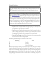
The Conformiq Computation Server can be started by double clicking the "Conformiq
Computation Server" icon in desktop (or directly executing conformiq-manager.exe in the
installation directory). Once started, QCS will minimize itself to the Windows system tray
that you can see on the lower right hand side of the Windows desktop.
i
As of Conformiq Qtronic 2.1.0, the Conformiq Computation Server is automatically started when the user starts Conformiq Eclipse Client and attempts to
establish a connection to Conformiq Computation Server. See the Section How to
Configure Conformiq Eclipse Client for more information on how to change this
default behavior.
QCS minimized to Windows system tray
i
As of Conformiq Qtronic 2.1.0, the Conformiq Computation Server has support
for distributing the calculation over multiple CPU's. This feature is always
enabled in the installed version and therefore does not need to be activated by the user.
26
User Manual
2.4.2 How to Uninstall Conformiq on Windows
Conformiq for Windows can be removed from your computer by using the built in feature
of Windows for uninstalling programs. In order to uninstall Conformiq, choose Conformiq
from the list of installed programs found from Add or Remove Programs from Control Panel of
Windows.
2.5 Installing Conformiq on Linux
Conformiq can be installed on most modern Linux distributions with Intel 586 (Pentium)
compatible processors. For support for other processors, please contact your supplier.
2.5.1 How to Install Conformiq on Linux
Conformiq Linux installer is provided as a bash script.
The installer can be used to install the Conformiq Eclipse Client or Conformiq
Computation Server or both. As mentioned in the Section System Requirements, Conformiq
Eclipse Client can be installed as a standalone application (RCP application) or as an Eclipse
plugin that requires an existing Eclipse installation. These two are provided in distinct
installer packages. Both of the installers will also allow the installation of Conformiq
Modeler, a light-weight modeling tool for drawing UML state machine diagrams, example
models, and more.
Unpack the installer package before continuing with the installation:
• Unpack the installer file using the tar command
tar xvfz conformiq-<version>-linux-libc-2.4.tgz
• Change to the installation directory
Installing Conformiq
27
cd conformiq-<version>-linux-libc-2.4
• Execute the install.sh bash script in the installation directory. This will start the
Linux installer.
./install.sh
The following list details the process of installing Conformiq on your computer:
1. Specify a destination directory for the installation. The default is
$HOME/conformiq. If the installation directory does not exist, the installer will
create one. Make sure that you have required permissions to write to the
destination directory.
2. Specify whether you want to install Conformiq Computation Server. The default is
yes. If you select server installation, the installer will install the server and database
components to the destination directory, and initialize the database appropriately.
3. Specify whether you want to install Conformiq Eclipse Client. The default is yes.
1 If you select the client installation and you are installing Conformiq Eclipse Client
as an Eclipse plugin, the installer will prompt you to specify the location of the
Eclipse installation. The default location that the installer looks is in
$HOME/eclipse.
4. In order to provide a smooth user experience of Conformiq Eclipse Client client,
the installer will recommend a few different memory configurations for the Eclipse
based client (These configurations are used by the Java Virtual Machine that is
responsible of executing the Eclipse. For more information about tuning Java
Virtual Machine please refer Memory Management in the Java HotSpot Virtual
Machine document available online). Select the one that suits your needs the best.
If you do not wish to deploy the memory configuration recommended, you can
continue without making changes to the configuration. The installer will not
28
User Manual
recommend this memory configuration if Conformiq Eclipse Client is not selected
for installation.
5. The installer will install the selected set of components to your computer.
6. At your own discretion, you may want to add the directory where Conformiq
resides to your $PATH, or create a symbolic link from '/usr/local/bin' or '/usr/bin'
to the individual executables.
The Conformiq Computation Server can be started by executing the command qcs in the
installation directory. For example, after installing QCS to the default location, QCS is
started as follows:
$HOME/conformiq/qcs
As of Conformiq Qtronic 2.1.0, the Conformiq Computation Server is automatically started
when the user starts Conformiq Eclipse Client and attempts to establish a connection to
Conformiq Computation Server. See the Section How to Configure Conformiq Eclipse
Client for more information on how to change this default behavior.
i
As of Conformiq Qtronic 2.1.0, the Conformiq Computation Server has support
for distributing the calculation over multiple CPU's. This feature is always
enabled in the installed version and therefore does not need to be activated by the user.
2.5.2 How to Uninstall Conformiq on Linux
• Remove the directory that you originally selected as the destination directory for
the installation. For example, if this directory is $HOME/conformiq, execute
rm -rf $HOME/conformiq
* If you created any symbolic links to the executables, remove the symbolic links.
Installing Conformiq
29
• Remove the Conformiq Eclipse Client "link file" from the Eclipse installation
directory. For example, if the Eclipse installation directory is $HOME/eclipse,
execute
rm $HOME/eclipse/links/com.conformiq.qtronic.client.link
2.6 Checking the QEC Installation
After Conformiq Eclipse Client has been installed, the next step is to check that the plugin
has been properly activated by Eclipse. The most straightforward way is to start Eclipse and
select Window > Open Perspective ... and check that Conformiq is listed there. If not, the
most likely reason is that the Java version that Eclipse is using is not recent enough or similar.
See Section How to Switch to Conformiq Perspective for more information about
Conformiq perspective.
Troubleshooting QEC Installation
If Conformiq is not listed in the list of available perspectives explained in the previous
section, it is recommended that you start troubleshooting by following the steps detailed
below:
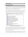
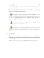
1. Select Window > Show View and select Other. This will open the Show view
wizard.
2. From Show view wizard, select PDE Runtime > Plug-in Registry. This will open
the Plug-in Registry wizard.
3. Locate com.conformiq.qtronic.client from the list of installed Eclipse plug-ins. If
the plug-in is not listed here, the installation has failed and you must reinstall the
Conformiq Eclipse Client. Make sure that you have the appropriate permissions to
write to the Eclipse installation directory.
4. If the com.conformiq.qtronic.client plug-in is listed in Plug-in Registry, check
30
User Manual
that the version of the Java compiler that Eclipse is using is 1.6 or higher. In case
you have multiple versions of Java installed on your computer, you may need to set
your PATH environment variable so that it lists Java version 1.6 first before older
versions and restart Eclipse.
If after taking the steps above, Conformiq is still not registered in Eclipse, please contact the
software provider.
Note that the plug-in registry is not available in all of the Eclipse packages. It is
recommended to use Eclipse Classic.
Checking the Version of QEC
The version of the QEC plugin can be checked by selecting Help > About Eclipse SDK.
This will open the About Eclipse SDK view where you can select Plug-in Details which
opens the About Eclipse SDK Plug-ins view. This view will list all the plugins that are
installed in Eclipse with version numbers. The QEC plugin is provided by Conformiq
Software and the plug-in name is com.conformiq.qtronic.client.
Customizing the Conformiq Perspective
The Conformiq perspective in the Eclipse user interface can be customized in a number of
ways. You can, for example, disable and enable some of the command groups in the tool bar.
In order to add or remove command groups from the tool bar, follow the steps detailed
below:
1. Switch to the Conformiq perspective, for example by selecting Window > Open
Perspective > Conformiq.
2. Select Window > Customize Perspective.... This will open the Customize
Perspective wizard.
3. Select the Commands tab.
4. Select the command groups that you want to have in the tool bar from the
Installing Conformiq
31
Available command groups.
i
Use the steps above if for some reason the Conformiq specific commands are not
visible in the tool bar in the Conformiq perspective.
2.7 License Management in Conformiq
Conformiq Designer is license managed software. This means that every time you run
Conformiq it checks for an electronic certification of your right to use it. (This does not
mean that Conformiq would contact any service outside your company, for instance, a
service provided by Conformiq Software at its own domain.)
The purpose of the license management features is not to define what your use rights are in
the first place, because this is done in the licensing agreements between you or your
company, and the copyright holders of Conformiq. Rather, the license management features
help you to abide within the terms of these agreements.
Keeping this in mind, there are three different mechanisms that Conformiq Designer uses to
verify your right to use the software:
• The evaluation version of Conformiq Designer makes use of evaluation keys,
which are character sequences looking like APO39-JK119-NCQOL-011LXZMNNM. When Conformiq Designer is running as the evaluation version it will
ask for an evaluation key. Evaluation keys have a limited validity time.
• Other versions of Conformiq Designer check for a right to use the software at
startup and then regularly until the software is closed.
In the last case, Conformiq Designer needs a license grant, which is a small electronic
document (actually, a block of a few lines) that certifies that Conformiq Designer can be
used in its present configuration at your local computer node. Conformiq Designer can get
access to this license grant in two ways:
• You can select the license file in Conformiq Designer via the GUI's license
32
User Manual
management features. The license grants fed in by this method are usually longterm, node-locked grants. This is known as node-locked licensing.
• Conformiq Designer can automatically check out the grants as short-term,
renewable grants from a license server. Conformiq Designer supports both Flexera
based license server and a simple web-based license server (but the license server
usually resides at your intranet server rather than on the public Internet). This is
known as floating licensing.
As already implied, there exist different configurations of Conformiq Designer. These configurations are not shipped or installed separately. Instead, Conformiq Designer can be
configured dynamically to run in any of these configurations. However, because different
configurations have different licensing requirements, probably not all of them are actually
usable for you. If you select a configuration that you do not have a license for, Conformiq
Designer will not work properly but will prompt you about a missing license and guide you
to reconfigure the product.
i
Licensing applies to Conformiq Eclipse Client, not to Conformiq Computation
Server. Conformiq Computation Server components can be installed freely on as
many nodes as you want.
2.7.1 Configuring Conformiq Feature Set
If you are conducting an evaluation of Conformiq, choose Conformiq Evaluation. In other
cases, choose the Conformiq version that matches your node-locked or floating licenses.
When in doubt, contact your system administrator.
Conformiq Designer will remember your choice and will not prompt you again for it.
However, you can reconfigure Conformiq Designer at your will by
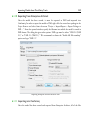
1. selecting Window > Preferences... in the main menu. This will open the
Preferences wizard.
Installing Conformiq
33
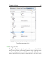
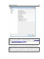
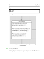
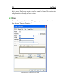
2. selecting Conformiq > Licensing from the Preferences wizard. This will open the
Conformiq License Management view shown in the figure.
Conformiq License Management view
2.7.2 Conformiq Evaluation
Conformiq provides limited time evaluation licenses for the prospective customers who are
interested in finding out the suitability for Conformiq Designer to their specific needs and
test environments. Prospects can download an evaluation copy of Conformiq Designer from
the Conformiq website and request the license online.
34
User Manual
If you are conducting an evaluation of Conformiq, make sure you have selected the
"Conformiq Evaluation" configuration (see above). If you do not have a valid evaluation
license already installed, Conformiq Designer will ask you for one. Enter the evaluation key
you have received when prompted. Conformiq Designer will notify you about the remaining
evaluation time every time you establish a connection to Conformiq Computation Server.
If you want to change the evaluation key while the current key is still valid, follow the steps
detailed below:
1. Select Window > Preferences... in the main menu. This will open the Preferences
wizard.
2. Select Conformiq > Licensing from the Preferences wizard.
3. Check the Evaluation License check box and enter the license text block.
Most features of Conformiq are available in the evaluation version.
2.7.3 Named User Licensing
If you have a named user license for your configuration and your node, you can provide the
license to Conformiq Designer in the license management dialog.
To configure a node-locked license, follow the steps detailed below:
1. Select Window > Preferences... in the main menu. This will open the Preferences
wizard.
2. Select Conformiq > Licensing from the Preferences wizard.
3. Check the Node-Locked License check box and click Select license file to select
the license file.
Named user licenses are files usually named as *.lic and they contain textual information
about the license. Typically you receive this kind of a license via e-mail. Save the license file
attached in the message and then select the path to file in Conformiq Designer. Conformiq
Designer notifies you whether the license was successfully added or not.
Installing Conformiq
35
i
The named user is technically identified by reading the login name of the user in
effect on a Windows or Linux machine. A named user license can contain (by
Conformiq’s discretion) multiple user names if there is obvious variation of names, e.g.
between Linux and Windows systems, such as “jsmith” and “john”.
2.7.4 Floating Licensing
Contractually, a floating network license creates the right to use Conformiq Designer on any
node within the licensing business organization, however only on one node at a time.
To employ floating licensing you must have either Flexera based license server or a web-based
license server for Conformiq Designer installed. The administration of the server is described
elsewhere; this section focuses on the use of Conformiq Designer given that a license server is
running.
i
A license is leased from the license server when the user starts to operate with a
Conformiq project and will stay that way until the user exits the Conformiq
Eclipse Client or closes all the Conformiq projects that are open. Technically, leases are
always time-bound and bound to a particular user. Once a lease has been created, it
cannot be prematurely terminated i.e. the user cannot explicitly "return" the leased
license back to the license server, but instead the lease terminates at the moment of its
expiration. A lease on a floating license is automatically refreshed by the Conformiq
Eclipse Client, which means that a new lease is issued for the same license on the same
node and bound to the same user name as the previously existing lease. This mechanism
enables a single user to roll over multiple leases on the same node, enabling the
continuous availability of Conformiq Eclipse Client during a working session. When the
user exits the Conformiq Eclipse Client, there are no further refreshes on the lease,
making the floating license available again after few minutes.
36
User Manual
i
Recall that licensing applies to Conformiq Eclipse Client only, not to Conformiq
Computation Server, allowing the user to work simultaneously with multiple
projects while still occupying a single license.
To configure the license server for use, follow the steps detailed below:
1. Select Window > Preferences... in the main menu. This will open the Preferences
wizard.
2. Select Conformiq > Licensing from the Preferences wizard.
3. Check the Floating License check box and enter the base URL for the server. You
will receive this base URL from your system administration, as it depends on where
the license server has been installed.
If your company is using Flexera based licensing solutions, the URL looks for example
"[email protected]". In redundant configuration, it can also be a triple of three
license
servers
separated
by
comma
",",
for
example
"[email protected],[email protected],[email protected]
".
If your company is using a simple Conformiq provided web-based license server, then the
URL to the license server binary is the "base URL" that Conformiq Designer users must
configure into their Conformiq installations; for example, "http://server.company.com/cgibin/cgiserver.exe". See Section License Server Management for more information.
You can also select the refresh interval for your floating license in the Conformiq Licensing
Preferences. Suppose you select an interval of one hour. Then Conformiq Designer will
initially check out a local license grant for one hour from the license server. This grant is
valid for an hour, and during this time you do not need to be connected to the license server.
When half or less of the grant time is left (30 minutes or less), Conformiq Designer will try
automatically, in the background, to check out a new grant from the server that will
supersede the old one. In this way, if you are connected to the server, you will always have
checked out a grant for at least 30 and at most 60 minutes.
Installing Conformiq
i
Usually the license server resides on an intranet web server, so if you have access
to the web server from the external Internet, it can be possible that you can check
out Conformiq licenses from outside your local network also. How this actually works
depends on how your company has organized external intranet access. Please note that
Conformiq Designer does not use HTTPS (secure HTTP) for accessing the license
server and therefore cannot log in on a secure web server, so you may need to use a VPN
solution or a local web proxy.
i
The floating license mechanism also works when the license server and licensing
client do not agree on the current (wall-clock) time, but if the time difference is
more than 24 hours in either way, licensing will stop working properly. Also, if you
adjust the clock at the licensing client while there are active grants for the client you may
find out that refreshed grants will not work properly. In this case you must wait until
your local license grants have expired and continue to use Conformiq Designer only
afterwards.
i
If you need to use an HTTP proxy in order to get access to the external network,
you can configure Conformiq Computation Server to use the HTTP proxy by
setting the http_proxy environment variable before running QCS. In Linux you can do
this by running export http_proxy=http://proxy.mycompany.com in sh/bash/ksh shells
and setenv http_proxy http://proxy.mycompany.com in csh/tcsh shells. In Windows,
the environment variable can be set for example by using the set
http_proxy=http://proxy.mycompany.com command. If your proxy requires a login
then the proxy address needs to be written in the format http://user:[email protected]:port in the above commands.
37
38
User Manual
2.7.5 Obtaining Node Identifiers
Sometimes you need to be able to obtain the node identifier for your local node manually.
The two cases are:
• You are ordering a node-locked license and your supplier must receive the node
identifier in order to bind the license to it.
• You are administrating the license server and you are ordering floating licenses for
it.
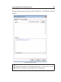
In order to get the node identifier, open the Preferences wizard and select Conformiq >
Licensing. The node identifier is shown on the bottom of the opened page. You can also
retrieve the node identifier by running the "Conformiq Node Identification" program (cqnode-id in Linux and cq-node-id.exe in Windows). This will show a popup window that
contains your node identifier. When the popup is shown, the node identifier has been copied
to your system's clipboard, so you can immediately paste it in any other application.
i
The purpose of the node identifier is to reliably distinguish between different
machines where Conformiq Designer might be used or where a Conformiq
license server might be installed. The node identifier is aggregated from details of the
node's hardware devices. It is possible, although not usual, that the hardware devices
change in a way that causes the node identifier to change. This may also happen if you
enable or disable, for example, wireless network devices from the BIOS. If you are
running floating licensing this is not a huge problem because the grants for the old node
will expire whenever they were going to expire anyway, after which you can check out
grants for the new node. In the case of node-locked licensing you must contact your
supplier who will help you to transfer your node-locked license to the new node.
2.8 License Server Management
If you want to provide floating licensing to your users you must install the license server. You
have two options, either using almost industry standard Flexera based licensing solution
Installing Conformiq
39
(previously know as Flexlm or simply Flex), or using simple Conformiq designed web-based
license server. Conformiq recommends using Flexera based licensing solutions for big
companies, and also if you've already deployed Flexera license server for some other licensed
software. In any other case, Conformiq's own web-based license server is usually easier to setup.
2.8.1 Flexera based license server
To provide floating licenses from an industry standard Flexera license server, you must install
Conformiq's vendor daemon named "cqdesign" (.exe) to your license server, and your
company's floating licenses. You must copy cqdesign vendor daemon to Flexera license
server's directory of vendor daemons, and then restart Flexera license server. For example
starting command can be "./lmgrd -c conformiq.lic" where Conformiq provided license file
conformiq.lic contains information about your floating licenses.
2.8.2 Web-based license server
This is a CGI (Common Gateway Interface) binary that you install (usually, copy into the
file system) into your web server in a location where it can be accessed via a URL.
i
For example, if you are using the Apache web server you must copy the binary to
a directory that has the ExecCGI option set, or that has been set as a general
location for CGI scripts by the ScriptAlias directive.
The server CGI binary will establish a license management database when it is run for the
first time. The location for this database cannot be changed in order to prevent accidentally
running multiple license server copies. On Windows the location is
C:\WINDOWS\Conformiq\licserv.db and on Linux /etc/conformiq/licserv.db. On both
operating systems the database file is a regular file.
40
i
User Manual
The web server must have write access to the directory and the database file when
it is executing the CGI binary.
i
The license database is actually an SQL database that resides inside the file. If you
try to modify the contents of the database by hand you will end up in a situation
where the server says that the integrity checks for the database fail. At this point the
database has been rendered unusable and the license server ceases to work. Do not
modify the database by hand.
Once you have installed the CGI binary (cgiserver.exe) to the correct location, you can
validate that the installation has been successful by opening the CGI binary via a web
browser.
For example, if you installed the binary on an Apache server in its default configuration on
server "server.company.com", try to access it via "http://server.company.com/cgi-bin/cgiserver.exe". If the installation has been successful and the database created correctly you will
receive a page showing an empty list of licenses and a text box where you can edit text (this
box is used for adding permanent licenses to the server).
The URL to the binary (as above) is the "base URL" that Conformiq Designer users must
configure into their Conformiq Eclipse Client installations; for example, "http://server.company.com/cgi-bin/cgiserver.exe".
Viewing Licensing Status
To view the licensing status, just open the CGI binary via a web browser. You will receive a
list of licenses with their corresponding active grants (if any).
Adding Licenses
To add licenses to the server, cut and paste the license block you have received from your
Installing Conformiq
41
vendor into the text box that is shown on the status page below the list of licenses and active
grants.
3 Testing with Conformiq
Testing with Conformiq
43
Conformiq Designer is a tool for offline generation of test scripts (the particular features
available depend on your licensing options). Conformiq Designer creates and executes tests
driven by design models. It is not in itself, however, a tool for creating these design models.
The reason for this is that Conformiq Designer supports multiple types of design models,
and the different types are created and modified using different tools:
• Java/UML models can be created using text editors and Conformiq Modeler, a
separate tool that is shipped with Conformiq distribution.
• Models created using some of the leading 3rd-party modeling tools.
To start testing with Conformiq Designer one needs first a design model (see Section
Conformiq in Software Process). One also needs further scripting back-end.
i
For more information about creating UML/Java models, see Creating Models in
QML. Scripting backends are discussed in Creating Conformiq Scripting
Backends.
3.1 Quick Start of Using Conformiq
The following list summarizes the steps when working with Conformiq Designer.
1. Switch to the Conformiq perspective by selecting Window > Open Perspective...
and then Conformiq.
2. Select Window > Preferences... to configure the license and the Conformiq
Computation Server location.
3. Create a new Conformiq project by selecting New > Conformiq Project. This will
also create a Test Design Configuration which 'owns' the coverage settings and
scripter plugins.
4. Select model files for the project by either importing or linking them to the
project.
44
User Manual
5. Import the project's model files into Conformiq Computation Server by clicking
Load model files to Computation Server.
6. Select coverage goals for the test design configuration that was automatically
created when the Conformiq project was created.
7. Select the Conformiq project and click Properties to configure Conformiq options.
8. Generate test cases by clicking Generate Test Cases from Model.
9. Analyze the test generation results in the Conformiq Eclipse Client user interface
after the test generation finishes.
10. Select a scripter plugin by selecting the test design configuration and clicking New
> Scripting Backend.
11. Render the test cases in the format specified by the scripter plugin by clicking
Render All Test Cases.
3.2 Deploying Example Conformiq Projects
The Conformiq Eclipse Client user interface component comes with a number of example
Conformiq projects. These projects can be deployed to Eclipse workspace using the
Examples Wizard.
Every example Conformiq project contains:
• a set of model files each demonstrating a different modeling challenge,
• pre-configured Conformiq project settings, and
• one or more pre-configured test design configurations.
The following example projects come with the Conformiq distribution:
Echo System
This is a "Hello World" system for Conformiq. It demonstrates a simple system
that takes as an input a message from the environment and sends the message
Testing with Conformiq
45
unmodified back to the environment.
Simple End-to-End System
This is an extended version of the "Echo System" that contains two state machines
that communicate with each other in the model. The state machine Receiver
receives a message from the environment, forwards the message unmodified to the
Sender state machine who then sends the message, once again unmodified, back to
the environment. See Chapter Creating Models in QML for more information
about state machines.
Triangle
This project demonstrates an example from Glenford J. Myers's book The Art of
Software Testing. The system receives three integer values as input which are
interpreted as representing the lengths of the sides of a triangle. The system then
sends an output message that states whether the triangle is scalene, isosceles, or
equilateral.
SIP UAC
This example demonstrates the behavior of the client side of the SIP protocol
(Session Initiation Protocol, specified in RFC 3261) on an abstract level. SIP is an
application-layer control (signaling) protocol for creating, modifying and
terminating sessions with one or more participants. These sessions include Internet
telephone calls, multimedia distribution, and multimedia conferences.
The SIP UAC model describes the partial functionality of a SIP User Agent Client (e.g. a
VoIP phone). The modeled behavior includes call setup, call termination by caller or callee
and call cancellation during call setup. The timers associated with these functionalities are
also modeled. The SIP UAC model assumes the system under test is interfaced through the
phone's user interface and the network.
Inventory System
This example project demonstrates the behavior of an imaginary inventory system.
This model specifically shows how you can create tests for a client-server inventory
46
User Manual
system by combining a client and a server model. The client's functionality is
defined through its user interface and its network messaging. The server behavior is
defined through its two different network interfaces, one for the client and one for
a management interface. The inventory system model is a model that combines
these two models through the common client-server network interface. The
generated tests will interact with the system under test through the client's user
interface and the server's management interface. Note that both the client and the
server models are complete and tests could be created from them by only
modifying the model's system block and the main()-function.
The example projects can be deployed to your current Eclipse workspace as follows:
1. Select File > New > Example.... This will open the New Example wizard.
2. Select Conformiq and an example project you wish to deploy to the current
workspace. Click Next.
3. In order to prevent project name clashes, the New Example wizard will ask the user
to give a name to the project. After naming the project, click Finish.
The Conformiq Eclipse Client user interface will now deploy the project to the current
Eclipse workspace.
After an example project has been deployed, the user can experiment with the actual test
generation. The test generation can be started by selecting Conformiq > Generate Tests as
detailed in Section How to Generate Tests. After the test generation completes, you can
analyze the test generation results in the Conformiq Eclipse Client user interface. For more
information about the analysis of the test generation results, please refer to Section How to
Analyze Test Generation Results.
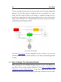
The usual flow in testing with Conformiq Designer is very simple as shown in the next few
how-to's.
Testing with Conformiq
47
3.3 How to Switch to Conformiq Perspective
The Conformiq perspective in Eclipse is a group of views and editors in the Workbench
window. The Conformiq perspective can exist in a single Workbench window with other
perspectives.
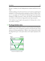
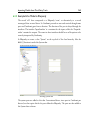
Switching to the Conformiq perspective is carried out by selecting Window > Open
Perspective > Conformiq. If the Conformiq perspective is not visible after selecting Window
> Open Perspective, select Other... from the drop down menu where Conformiq is shown.
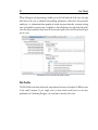
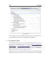
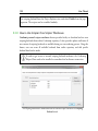
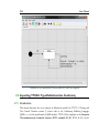
The Conformiq perspective looks as shown in the Figure. The different views and editors are
covered in detail in the following sections.
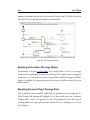
Conformiq Eclipse Client
3.4 How to Configure Conformiq Eclipse Client
As test generation is carried out by a Conformiq Computation Server, the Conformiq Eclipse
Client must be configured with a Conformiq Computation Server address and TCP port
number before loading models or generating any test cases.
48
User Manual
i
As of Conformiq Qtronic 2.1.0, the Conformiq Eclipse Client can be configured
to use a "Local computation server" or a "Remote computation server".
Local computation server
By default, the Conformiq Eclipse Client always accesses a Conformiq
Computation Server running on localhost listening on TCP port 2727. If a server
is not running when the client attempts to establish a connection with it, a server is
started automatically. This automatically started server is only for local use and will
not accept remote connections from other computers on the network. This server
will also be shut down automatically together with the Conformiq Eclipse Client.
If you want to have a server which keeps waiting for and accepting connections
from multiple clients on different computers, then it is necessary to start a server
from the Start menu.
Remote computation server
The Conformiq Eclipse Client can also be configured to use a Conformiq
Computation Server running on a remote host. The server address can be either a
hostname or an IP address. By default, the TCP port number that the Conformiq
Computation Server uses is 2727. It is perfectly valid to enter "localhost" as a
remote computation server, but this will disable the automatic starting of a
Conformiq Computation Server on localhost if no server is running.
i
Test generation is a computationally intensive task and therefore it is
recommended to run Conformiq Eclipse Client and Conformiq Computation
Server on distinct computers. The recommended setting is thus "Remote computation
server".
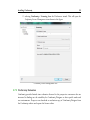
In order to change the settings, follow the instructions given below:
1. Open preferences by selecting Window > Preferences....
Testing with Conformiq
49
2. From Preferences, select Conformiq.
3. Select "Local computation server" or "Remote computation server" based on your
setup and preferences
4. In case you select "Remote computation server"
1 Enter the address and the port number of the Conformiq Computation Server.
2 Choose whether you wish to utilize any CPUs from the client workstation for
running your test generation tasks by adjusting the “Use additional CPUs from this
node” slider. These CPUs will be added to the cluster for running test generation
tasks started from this workstation (but not from any other node on the network).
You may choose a value between zero and the (automatically detected) number of
CPUs available on the workstation.
i
The "Use additional CPUs from this node" setting will apply independently to
every test generation task started from the client. This means that a new test
generation task will try to use the given number of CPUs even if there is another task
started from the client already running. If you intend to run several test generation tasks
from the same client at the same time, consider lowering the number of CPUs to reserve
for a single task (before starting any of the tasks) to avoid unnecessary load on the
system.
i
Note that if you have used local computation services (ie you have used 'Local
computation server' or you have selected 'Use additional CPUs from this node')
when changing the Conformiq computation settings, you may need to manually
terminate the local computation services now.
i
The location of the Conformiq Computation Server is an Eclipse workspace
specific setting, therefore all Conformiq projects in an Eclipse workspace share
50
User Manual
the same Conformiq Computation Server location. See Section Managing Conformiq
Projects for more information about Eclipse workspaces.
3.5 How to Work with Conformiq Projects
Testing setups are managed as projects in the Conformiq Eclipse Client. They are structural
units that can be opened and closed. Conformiq projects contain the following information:
• Model files
• Test design configurations
• Test generation options
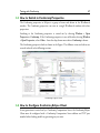
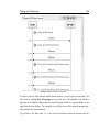
In order to create a new Conformiq project, follow the steps below:
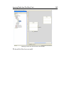
1. On the main menu bar, select File > New Conformiq Project. The New Project
wizard opens.
2. In the Project name field, enter the name of the new Conformiq project.
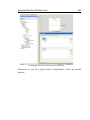
3. Click Next. This will open the Deploy Model Files page which can be used to
automatically generate skeleton model files in addition to a new Conformiq
project.
Testing with Conformiq
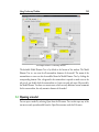
51
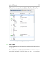
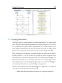
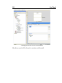
An example Conformiq project in Eclipse
Project Explorer
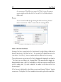
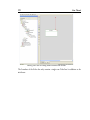
The Deploy Model Files page has a checkbox with title Deploy default model files that is
unchecked by default. If you decide to leave the checkbox unchecked and click Finish, a new
Conformiq project will be created which will be visible in the Project Explorer. Note that
this operation will also create a single Test Design Configuration. (More information about
Test Design Configuration is given in Section How to Create Test Design Configurations).
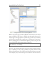
If you, on the other hand, wish that the Conformiq Eclipse Client would also automatically
generate a set of skeleton model files for you, the option can be checked. When the option is
checked, the next step is to enter the name of "the main class" to the text box titled Name of
the main class. This name will be used by the Conformiq Eclipse Client to create an active
class with a state machine that has the given name. Note that this name must be a valid Java
identifier. Once the name has been entered, click Finish. This will, in addition to creating a
new Conformiq project with a single test design configuration, populate the model folder
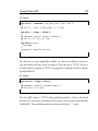
with the four files detailed below (note that in all the files shown below, the name MainClass
is substituted with the user supplied name of the main class):
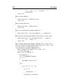
• SystemBlock.cqa which will contain the definition of a system block with
commented out examples of how you can then add the ports and records to the
file.
52
User Manual
/** Declaration of the external interface of the system being modeled. This is
specific to system modeling; a similar construct does not appear usually in
programming languages. In this "system block", we initially declare one
inbound
interface (in) and one outbound interface (out). The identifiers 'in' and
'out' are the names for the interfaces in the model. After the colon we
list the types of records that can possibly go through the interface in
question. */
system
{
Inbound in : MyMessage;
Outbound out : MyMessage;
}
/** Declaration of a message type, which is technically presented as a "record
type". It is a record of pure data. This record type 'MyMessage' is empty,
i.e. it does not contain any actual data fields. */
record MyMessage { }
• Main.cqa which will contain the main entry point as follows:
/** Main entry point to the model i.e. the place where the system "starts". */
void main()
{
// Instantiate the 'MainClass' and start execution of the state machine.
MainClass mc = new MainClass();
mc.start("MainClass");
}
• MainClass.cqa is generated based on the user-specified name of the "main class"
with the following content:
Testing with Conformiq
53
/** Declaration of the 'MainClass' state machine. This state machine has its
own execution thread and it supports communication with other state
machines via ports. */
class MainClass extends StateMachine
{
/** The default constructor. */
public MainClass() { }
}
• MainClass.xmi which will contain a state chart corresponding to the main class
with an initial state, a basic state named "State1" and a transition from the initial
state to the "State1".
In order to close a Conformiq project, follow the steps below:
1. Select the Conformiq project in the Project Explorer view.
2. Click Close Project in the pop-up menu.
i
It is recommended that you close any Conformiq projects when you are not
working with them, because the closing of a Conformiq project will free some
resources from the Conformiq Computation Server.
To re-open the Conformiq project:
1. Select the Conformiq project in the Project Explorer view.
2. Click Open Project in the pop-up menu.
To delete a project and remove its contents from the file system:
1. Select the Conformiq project to be removed in the Project Explorer view.
2. Click Delete on the pop-up menu.
3. In the dialog that opens, select Also delete the contents under ...
4. Click Yes.
54
User Manual
If you do not wish to delete the contents, simply select Do not delete contents from the
opened dialog.
i
If the model files and scripter plugins are imported to the project (the process of
adding model files and scripter plugins to the project is explained later), the
original files are left intact even if you choose Also delete the contents under ... in the
dialog window.
See Section Managing Conformiq Projects for more information about Conformiq projects.
3.6 How to Select Models
Each Conformiq project contains a folder called model. This is where the model from which
the tests will be generated will reside.
i
The manifest file concept used in Conformiq Qtronic 1.X is no longer used and
the model files are individually selected for the project instead of a single manifest
file.
The first step in importing the model into Conformiq Designer is to add model files to the
model folder. There are a couple of ways to do this:
The first option is to actually copy the model files into the Conformiq project. This means
that the original model files and imported model files are totally distinct, thus changes are
not reflected automatically between these physical resources. The steps to import model files
into a Conformiq project are detailed below:
1. Select the model folder under a Conformiq project in Project Explorer.
2. Select Import from the pop-up menu. This will open the Import wizard.
3. Select General > File System and click Next.
4. Click the Browse button on the opened page to select the directories from which
Testing with Conformiq
55
to add model files. Click OK once the directory has been selected.
5. From the pane on the right hand side select those files that are part of the model
and click Finish.
The second option is to create a link to the model files in the file system. This means that the
Conformiq project does not contain the model files, but just file links to them. The steps to
create file links to the actual model files are detailed below:
1. Select the model folder under a Conformiq project in the Project Explorer.
2. Select New > File from the pop-up menu. This will open the New File wizard.
3. Click Advanced and check Link to file in the file system.
4. Select Browse... which will open a file selector.
5. Navigate to the model file and select OK.
6. Finally click Finish in the New File wizard.
7. Repeat the steps above for each file that is part of the model.
A convenient way to work with linked resources is to use path variables which are used to
specify locations on the file system. The location of linked resources may be specified relative
to these path variables. By using a path variable, you can share projects containing linked
resources with team members without requiring exactly the same directory structure as on
your file system.
i
In order to specify a linked resource in a parent directory as being relative to a
path
variable,
you
must
use
the
following
syntax
$
{PATH_VARIABLE}../../MyResource.txt. Please note that there cannot be a
slash (/) character between the path variable name and "..".
Path variables are created as follows
1. Select Window > Preferences.... This will open the Preferences wizard.
56
User Manual
2. Select General > Workspace > Linked Resources.
3. Select New... and enter the name of the new path variable and the location.
Now when you link a model file to your Conformiq project, you can do it by using this path
variable. Instead of defining the absolute path to the model file, you select the path to the
model file that is relative to the path variable. This way, when other members of your team
use the same Conformiq project, they can redefine the path variable to point to a proper
location in their file system.
See Section Managing Conformiq Projects for more information about Conformiq projects.
Once the model files have been imported from the file system to the Conformiq project, the
model can be loaded to the Conformiq Computation Server by selecting Load Model in the
tool bar. This will send the model files to the Conformiq Computation Server, which then
imports the model. The status information in addition to warning and error messages is
shown in the Eclipse Console.
Eclipse console showing results of successful model import
i
Model files are always inserted into the model folder. This is where Conformiq
Designer will look for model files, nowhere else. Within the model folder, you
Testing with Conformiq
57
can have a directory hierarchy so that logically distinct model parts (such as server
components and client components) can be placed into different subdirectories. Note,
however, that all the files under the model directory are treated as part of the model;
therefore you cannot place, for example, documentation files under the model directory.
3.7 How to Create Test Design Configurations
Test design configurations were introduced in Conformiq Qtronic 2.0. Test design configurations allow the user to create different profiles with different coverage settings and scripter
plugins for different testing purposes. For example, the user may wish to have a test suite for
verifying very basic requirements of the system and another test suite for verifying very
detailed corner cases such as boundary values of integral comparisons and the like. In this
particular case, the user can define two distinct test design configurations to a single
Conformiq project: one for verifying the very basic requirements and another for verifying
the more detailed corner cases.
Test design configurations contain a set of coverage settings and a (possibly empty) set of
scripter plugins. In order to create a new test design configuration for a Conformiq project,
follow the steps below:
1. Select the Conformiq project in the Project Explorer view.
2. Select New > Test Design Configuration from the pop-up menu. This will open
the New Test Design Configuration wizard.
3. Enter the name of the new test design configuration into the Test Design Configuration name field and click Finish.
58
User Manual
Create a new Test Design Configuration
Existing test design configuration can be duplicated via Duplicate; The operation creates a
duplicate of the given test design configiration including the coverage settings, scripting
backends, and their settings. The name of the duplicated test design configuration is
"<original DC> (copy)", so for example a duplicate of "DC 1" will be named as "DC 1
(copy)". Naturally the name can be changed via Rename. In order to create a duplicate of an
existing test design configuration, right click the test design configuration in the Project
Explorer and select Duplicate from the context menu.
Note that when a Conformiq project is created, a single Test Design Configuration is created
by default. For more information on creating and working with Conformiq projects, refer to
Section How to Work with Conformiq Projects.
3.8 How to Create Use Cases
Conformiq Designer offers the ability to specify use cases separately from the modeled
behavior – sometimes also referred to as test purposes. These use cases represent partial or full
sequences of messages exchanges with restrictions on data based on the specified system
interface and they are used to describe a particular model behavior, i.e., a run of the model.
A use case in Conformiq describes essentially high level, usually partial I/O sequence that a
system under test (i.e., the black box) is expected to reproduce. For each message in such a
Testing with Conformiq
59
sequence the message type and the port (as specified in the system interface specification of
the model capturing the system operation) and expected time stamp have to be specified. By
default any message contents are accepted for a message but can be refined by further
constraining the message field values to specific values. Secondly, one or more so called
“gaps” can be inserted into any point at these sequence to express that any messages can
arrive or be sent on any port before the next message in the sequence occurs in a generated
test. Besides the reuse of the system interface specification, use case specification is
completely independent of the specification of functional behavior, i.e., it is possible to
specify use case or (partial) message sequences that do not comply or violate to specified
system operation.
3.8.1 Why Create a Use Case
Use Cases can be used to select specific data values to generate tests or to select specific test
sequences to be part of the generated test suite. In addition, the Use Cases can be used in
some cases to guide Conformiq's test generation heuristics over computationally hard spots
in the model without increasing look ahead depth (See Section How to Configure Global
Testing Parameters for more information about lookahead depth option), and thus
decreasing the time required in the test generation.
Use Cases as "coverage items"
Conformiq Designer supports several different test generation heuristics that are
used to aid in selecting a good set of tests; requirement, state, and transition
coverage, just to name few. A Use Case that describes a run is used as a test
generation heuristic providing further coverage items for the test generation to
consider when carrying out the actual state space expansion and in test selection.
What we are interested in here is to see that the generated test suite also covers the
identified Use Cases.
Use Cases are "extended functional requirements"
Functional requirements are textual annotations in the model that are used to
establish direct links to identified functional requirements (see Section
60
User Manual
Requirements on how to use requirement keyword). Functional requirements
can be quite elaborate for describing a sequence of steps that needs to be taken in
order to fulfill the requirement. Therefore, Use Cases can be used to model more
elaborate functional requirements that describe (partial and abstracted) sequences
of steps.
Use Case can be used to guide test generation
Sometimes Conformiq Designer does not generate tests for a particular part of the
model because these model parts are outside of what the tool can see and reach
within the "look ahead". For example, a behavior that can be reached by taking a
certain action several times, none of which adds to the coverage. Use Case can be
used to guide and steer the test generation algorithm to reach these areas in the
model by giving it explicit instructions on how to expand the state space.
An example test generation where the Conformiq Computation Server reports which
Use Cases it has successfully tracked during the test generation
Testing with Conformiq
61
3.8.2 Basic Features of a Use Case
No Modeling Required to Define a Use Case
Use Cases are described in the Conformiq Eclipse Client user interface and you do not need
to define a separate Use Case model to capture a Use Case.
Data Abstraction
A Use Case can be described without giving actual values for all the data. Instead, a data
value that we do not care about in the Use Case can be abstracted by explicitly saying that
the given data item can have any value.
Partial Behavior
A Use Case does not need to be a full trace starting from the beginning of the system model
containing all the steps that we need to follow in order to run the Use Case. Instead, a Use
Case can be partial so that the Use Case does not need to start from the beginning of the
system model. In addition, it is possible that some of the steps are totally omitted in the Use
Case.
How To Manage Use Cases
Coverage Editor (See Section Coverage Editor) is used when creating Use Cases. The
Coverage Editor contains a top level hierarchy, Use Cases, which can contain folders and
individual Use Cases. Using Coverage Editor, you can
Add Folder
You can add folders to the Scenario hierarchy by right clicking the folder within
the hierarchy and selecting "Add Folder" from the context menu.
Delete Folder
You can remove a folder by right clicking the folder and selecting "Delete" from
62
User Manual
the context menu. If the folder is not empty, the "Delete" action will prompt a
question whether to delete also the Use Cases and Use Case Folders within the
folder as well.
Rename
You can rename the folder by right clicking the folder and selecting "Rename"
from the context menu. If there is a name clash, the renaming will fail
An example Conformiq project with two Use Case folders
How to Create Use Cases
An empty Use Case is created in the Use Cases hierarchy by right clicking a folder in the
hierarchy and selecting "Add New Use Case". The operation gives a default name to the Use
Case which is "Use Case (n)", where n is smallest value that makes the Use Case unique.
You can also convert a test case into a Use Case by dragging-and-dropping the test from the
"Test Cases" view to a folder in the Coverage Editor. The same test can be dragged-anddropped multiple times to the Use Case hierarchy, in which case copies are created. In the
case of a naming clash, "(n)" suffix is added for the smallest 'n' such that the Use Case
becomes unique.
A Use Case can be duplicated by right clicking a scenario and selecting "Duplicate" from the
context menu. The duplicate Use Case is renamed as above and it appears in the same folder.
Testing with Conformiq
63
Each Use Case has a coverage setting; the setting can be TARGET, DON'T CARE, or
INHERIT (See Section How to Configure Design Configuration Specific Testing
Parameters for more information about the coverage settings). Compared to other coverage
goals, Use Cases can be only targeted or ignored, but not blocked or asserted. Conformiq
Designer analyzes those Use Cases that are TARGETs or thate INHERITs a TARGET
setting.
3.8.3 Defining a Use Case
The actual Use Case is described in terms of external message take-over’s, i.e., a Use Cases is
a sequence of inputs and outputs typed by records and ports of a model, just as a test case,
but with the additional feature that the following items can be marked "don't care":
1. Timing
2. Message field values
A valid Use Case contains at least one message. Between messages it is possible to add a
"Gap". A gap denotes zero or more "don't care" messages. Gaps can also be at the beginning
or end of the Use Case to denote that more messages are allowed “heading” or "trailing" the
messages. Note that there is always an implicit Gap at the end of each Use Case.
The Use Cases are defined directly in the Conformiq Eclipse Client user interface in the "Use
Case Editor" and require no modeling efforts. The following set of actions can be performed
via the Use Case Editor:
Add Message
New messages can be added at any point in the sequence. You can select a port and
a record type from pull-down menus. The record is added with all fields set to "any
value". The port defines the direction of the message (input/output) and, for
convenience; this is indicated in the left hand side of the view with an arrow icon.
The wall clock value is set to "any value" as well. The content of pull down menus
is empty before the user loads the model for the first time.
64
User Manual
Fill / Edit value
You can change a field/timer value from "don’t care" to a defined field/timer value.
If you fill a field value, a default value for the given field is filled in. If you fill in
the timer value, the timer value of the previous defined message is filled by default.
If you fill in the timer value of the first field, the timer value is by default set to 0.0.
It is an error to set a smaller timer value from a previous message and any attempt
to do so will cause an error "Invalid value for timer. Timer value must be equal or
greater than the timer value of a previous message".
i
When editing a String field, you must leave the quotation marks out so instead of
entering for example "Hello World" you should enter simply Hello World.
Add "Gap"
Between messages, it is possible to add a "Gap". A gap denotes zero or more "don't
care" messages. Note that Gaps can be also at the beginning or the end of the Use
Case to denote that more messages are allowed "heading" or "trailing" the
messages. An implicit Gap is always added to the end of the Use Case.
Remove Message / Gap
You can remove any individual message from the Use Case. If the removed
message is between two Gaps, the Gaps are merged in to one automatically.
Undo
You can undo the previous actions via the Undo action
Testing with Conformiq
65
Defining the Use Case via the Use Case Editor. Note that in the Figure, the
method field is of type String and we have omitted the quotation marks from the
string literal and entered simply INVITE
3.8.4 Updating a Use Case
During the modelling effort, it might be required to add, remove or modify fields of the
records of the SUT interface. If such changes are made, the changes usually affect also use
cases. After reloading the model, new record fields are automatically added to all use cases
with "any value" as content. If you remove or rename some field, the field with an obsolete
66
User Manual
name and a value shows in red, and you can remove the red field by right clicking and
selecting "Delete" from the context menu or simply pressing "Del" key when such an
obsolete red field is selected. Before removing a field, the value should be checked and
depending on the semantics of the model, a value of some other field might require modification to preserve the semantics of the Use Case.
Also, a use case with obsolete field names shows up as red in Coverage Editor too. Those use
cases will be ignored during the test execution until you remove all obsoleted red fields.
3.9 How to Configure Test Generation
There are two different "types" of test generation parameters in Conformiq Designer: those
that are general and global across different test design configurations, and those that are
bound to specific test design configurations. For example, the concepts of lookahead depth
and only finalized runs are generic as they are properties that evolve from the model.
3.9.1 How to Configure Global Testing Parameters
To modify the project wide testing parameters, follow the steps shown below:
1. Select a Conformiq project in the Project Explorer.
2. Select Properties from the pop-up menu. This will open the Properties wizard.
3. Select Conformiq from the left hand side of the view.
Testing with Conformiq
Configuration view for Conformiq options
The properties shown in the view are as follows:
Lookahead Depth
Controls the amount of lookahead for planning the test scripts. The value of the
lookahead corresponds to the number of external input events to the system or
67
68
User Manual
timeouts. Selecting values from the left correspond to lower lookahead values.
When Conformiq Designer plans the tests, it intellectually selects interesting values
for data based on the logic in the design model. If the logic that manipulates the
data is after a certain number of external events, the lookahead value must be
increased, as Conformiq Designer must be able to "see" this in order to make
decisions on the data values. If you set this value too low you can miss some tests
(of course, you will see this from the coverage reporting). On the other hand,
having the value too high can cause very high test generation times. Therefore,
reasonable values for lookahead depth are recommended and you should always
start with the lowest possible value. Practically, usually the third level (color cyan)
is the highest that you need to go and if this is not sufficient, it is likely that there is
some problem in the model. (Note that Lookahead Depth can also be increased
locally only for a certain model part using a QML modeling language construct
cq_increase_lookahead() described in Section Miscellaneous Functions)
Maximum Communication Delay
Defines the communication slack, i.e., the time interval in which it is OK to
deliver a message. Recommended values are from 3 to 10 seconds, but this depends
on your application. As a rule of thumb, the latency value should be at most 1/2 of
the granularity of timeouts in your system, if any. For example, if your system has a
timer that expires in ten seconds, you should not use a latency value higher than 5
seconds.
Enable Model Profiling
This option is used to enable or disable the integrated model profiler which
provides guidance for optimizing Conformiq models by pinpointing their
problematic constructs, i.e., those model parts on which Conformiq Designer
spends most of its time. See Section Model Profiler for more information.
Require Conversion for Interoperability Testing
When this option is selected, a require statement is handled as an assert
statement instead whenever it is evaluated in a named thread which was last
Testing with Conformiq
69
awakened by receiving a message from a named thread; or in a thread which was
last awakened by a timeout when it was not waiting for any external interfaces. The
rationale with this feature is that the best practices of Conformiq modeling state
that a require should happen as soon as possible. So when a require imposes
something on an incoming message (the common case), it should happen
immediately after the message has been received. Given that, in general a require
pertains to the last message received, therefore if the last message received is an
inter-component message (from a named thread to a named thread), the require
can be assumed to be related to that. See Section Assertion Like Functions for
more information about require and assert statements.
Only Finalized Runs
When 'Only Finalized Runs' is selected, Conformiq Designer will only generate
test cases that end the system in a "clean" state. When this setting is activated, only
such test cases are accepted to the generated test suite that would cause all threads
in the model to terminate. In practice, this usually means that a main statechart has
entered one of its final states.
Stop at Full Coverage
When 'Stop at Full Coverage' is selected, the test generation is automatically
stopped immediately upon reaching 100% overall coverage (ie. all the TARGET
goals have been reached).
Stop at Full Requirement Coverage
When 'Stop at Full Requirement Coverage' is selected, the test generation is
automatically stopped immediately upon reaching 100% requirement coverage (ie.
all the TARGET requirements have been reached). This option takes precedence
over Stop At Full Coverage option, therefore selecting Stop At Full Requirement
Coverage disables Stop at Full Coverage and will cause the test generation engine to
automatically stop when reaching 100% requirement coverage and not to continue
until 100% overall coverage has been attained.
70
User Manual
i
Note that when Stop At Full Requirement Coverage or Stop At Full Coverage have
been selected it is not guaranteed that the test suite is stable across multiple test
generation runs, therefore it is not advised to enable these if stability of the generated
test suite is of importance.
OSI Methodology Support
Selecting this option activates the "OSI Methodology" feature which provides
support for generating test suites conforming to the OSI methodology for
organizing test cases as laid out in the ISO 9646-1 standard. The following applies
when the feature is enabled: (1) all the generated test cases are divided into three
sections: Preamble, Body, and Postamble, (2) every generated test case is automatically named by the name of one of the requirements that is verified in the Body,
except if the Body does not verify any new requirements, in which case it is named
by the name of one of the structural checkpoints that is verified in the Body, and
(3) the generated test cases are ordered in dependency order, so that typically later
test cases depend on earlier ones but not vice-versa. See Section How to Generate
Tests for more information about test selection and ISO 9646-1 Test Organization
support.
Automatic Test Case Naming
This option is used to enable the "intelligent test case naming" feature that aims to
select meaningful names for the test cases based on the model structure that each
test case covers. See Section Intelligent Test Case Naming for more information.
Test Case Name Prefix
This option is used to define the default name prefix that is given to new test cases.
This option is only used when the Automatic Test Case Naming has been disabled.
By default this value is 'Test Case ' which means that when a new test case is
generated, they are given names such as 'Test Case 1', 'Test Case 2' and so on. For
more information about naming or renaming test cases, please refer to Section
Testing with Conformiq
71
Naming Test Cases.
Enable Perturbation Support
This option is used to enable Perturbation support (Perturbation is a Conformiq
Designer feature that allow you to generate tests with non trivial data distribution.
See Section Perturbation for more information)
Perturbation seed
This option is used to set the seed value for the perturbation algorithm. The value
must be integral. (See Section Perturbation for more information) This option is
enabled only when Enable Perturbation Support is turned on.
Number of test variants
This option is used to set the how many variants of each test case the Conformiq
Designer should aim to generate. The value must be integral. (See Section Perturbation for more information) This option is enabled only when Enable
Perturbation Support is turned on.
Apply default data selection heuristics in addition
This option is used to indicate that Conformiq Designer should generate a test
variant that has been generated by applying the default data selection algorithm of
the tool. (See Section Perturbation for more information) This option is enabled
only when Enable Perturbation Support is turned on.
Requirement and Test case Synchronization
The requirement and test management tool integration components are selected,
enabled, and configured here. See Chapter Test and Requirement Management
Tool Integrations for more information about available integration components
and their configuration.
72
i
User Manual
Generic offline test generation parameters may not be changed during offline
script generation so these options are all disabled while generating tests.
3.9.2 How to Configure Design Configuration Specific Testing Parameters
Each test design configuration has its own set of model driven coverage criteria that is used by
Conformiq Designer to select a set of test cases to form a good test suite. The coverage goals
are used to guide Conformiq Designer to look for certain behaviors from models or to enable
certain behaviors, i.e., to generate test cases that "cover" the coverage goals in the model
whether they are related to the constructs in state machines (such as states and transitions) or
to the constructs in the action language (such as conditional branching or statements). In
Conformiq Designer it is defined that a test case covers a certain coverage goal if executing
the test against the model itself would cause the goal to be exercised.
Coverage options are organized into a hierarchy where atomic coverage options are contained
inside groups. The coverage groups are a way to organize and present atomic coverage
options to the user. Each coverage option can have the following setting:
Denotes a target goal. Guides Conformiq Designer to look for behaviors that cover
each target goal.
Denotes an ignored goal ("do not care"). Conformiq Designer will ignore these
goals while generating the tests.
Denotes a blocked goal. Guides Conformiq Designer to omit all the scenarios
where the given coverage option is covered. Thus the distinction with Do not care and Block
is that goals marked as Do not care can still be covered in the generated tests, they are simply
not goals for the tool. Conformiq Designer will not generate a test that would exercise a
blocked coverage option, therefore with blocked coverage options the user can prevent
Testing with Conformiq
73
Conformiq Designer from generating test cases that realize certain unwanted test scenarios.
Denotes an assertion goal. Reaching an assertion goal means that the model is
fundamentally wrong, thus internally inconsistent and causes Conformiq Designer to trigger a
run-time error. Assertion goals should be used to mark parts of the model that are logically
"impossible" in order to discover modeling errors.
The fifth option is Inherit, i.e., the coverage option inherits the setting from the coverage
group containing the coverage option.
The Coverage Editor is used to edit coverage settings. In order to open the view, double click
a test design configuration under a Conformiq project in the Project Explorer. This will open
the view as shown in the Figure. Note that the view will contain relevant information only
once the model has been loaded to the Conformiq Computation Server. In this view, there
are two columns for each test design configuration: the left hand side corresponds to the
coverage setting (intention), and the right hand side column corresponds to the current
coverage status (result). When the cell is edited (left hand side column), the coverage status
will be kept as is, but the test design configuration name in the column header is marked
with an asterisk (*). When test generation is finished (completed), this asterisk is removed.
74
User Manual
Selecting model driven coverage criteria in Coverage Editor
See Section Coverage Editor for more information about analyzing coverage status
information.
i
With enhanced coverage goal editing features introduced in Conformiq Qtronic
2.0, users have finer grained control over selected structural features, enabling
them to set coverage setting to individual structural features: now users can select only
Testing with Conformiq
75
an interesting subset of the structural features instead of having to set none or all of the
coverage goals related to a given structural feature.
The following coverage settings are related to state machines and they are not visible if there
are no state machines in the model.
State Coverage
Guides Conformiq Designer to look for behaviors that cover every UML level state
at least once (not visible if there are no states in the model).
Transition Coverage
Guides Conformiq Designer to look for behaviors that cover every UML level
transition at least once (not visible if there are no transitions in the model).
2-Transition Coverage
Guides Conformiq Designer to look for behaviors that cover every pair of two
subsequent UML level transitions at least once (not visible if there are no
transitions in the model).
Implicit Consumption
Guides Conformiq Designer to test that the system correctly ignores messages that
are not handled on any transitions going out from a UML state. A word of
warning: enabling implicit consumption may not be what you really want.
Without implicit consumption selected, Conformiq Designer focuses testing on
the explicitly modeled message handlers. With implicit consumption, Conformiq
Designer may also send system messages that are not handled in your UML
diagrams.
The following configuration options are related to conditional branching. These options are
not visible if there is not such a conditional branching in the model.
76
User Manual
Boundary Value Analysis
Guides Conformiq Designer to look for behaviors that cover the boundary value
cases for all the arithmetic comparisons. Boundary value analysis is a technique to
determine tests covering known areas of frequent problems at the boundaries of
input ranges. In boundary value analysis the boundaries partition the input domain
and we assume that the system partitions the input into a set of domains in which
the system's behavior is similar. Due to this, we assume that if an input from a
domain causes an error then all the inputs of that domain will cause a similar error
and if an input from a domain does not cause an error, then all the inputs of that
domain will fail to produce an error. Based on these assumptions, Conformiq
Designer attempts to cover the structure of the input as follows:
• For every arithmetic comparison 'x = y' and 'x != y', cover cases 'x < y', 'x = y', and
'x > y'.
• For every arithmetic comparison 'x < y', cover cases 'x < y - 1', 'x = y - 1', 'x = y',
and 'x > y'.
• For every arithmetic comparison 'x > y', cover cases 'x < y', 'x = y', 'x = y + 1', and
'x > y + 1'.
• For every arithmetic comparison 'x <= y', cover cases 'x <= y - 1', 'x = y', 'x = y + 1',
and 'x > y + 1'.
• For every arithmetic comparison 'x >= y', cover cases 'x < y - 1', 'x = y - 1', 'x = y',
and 'x >= y + 1'.
Branch Coverage
Guides Conformiq Designer to look for behaviors that cover every QML level
branch (such as then and else branches of if statements) at least once.
Atomic Condition Coverage
Guides Conformiq Designer to look for behaviors that cover every QML level
atomic condition branch (such as left and right hand sides of a Boolean and) at
Testing with Conformiq
77
least once. Note that because the modeling language uses short-circuit evaluation
for Boolean connectives, there are value combinations that cannot be meaningfully
tested in general. For example, in the case of x && y, Conformiq Designer will
not attempt to generate a test case where 'x' would be false and 'y' would be true.
The reason is that the short-circuit evaluation rule will prevent 'y' from being
evaluated after it has been found that 'x' evaluates to false, which makes it possible
that the value of 'y' may depend on the assumption that 'x' evaluates to true. (Note
that 'x' and 'y' can be both, e.g., method calls.)
The following configuration options are related to general control flow.
Method Coverage
Guides Conformiq Designer to look for behaviors that cover every QML level
method at least once. Note that this coverage option essentially has no effect on the
values passed to methods.
Statement Coverage
Guides Conformiq Designer to look for behaviors that cover every QML level
statement at least once.
The following coverage options belong to the "dynamic coverage goals" group, i.e., these
coverage goals are calculated by Conformiq Designer on the fly as it analyses the model.
Because of this on-the-fly calculation, Conformiq Designer will not give coverage percentage
for these goals and these coverage goals do not have an effect on the final coverage figures.
Parallel transition coverage
The parallel transition option is used to guide Conformiq Designer to look for
behaviors that cover every parallel transition configuration. The major new benefit
of this feature is that Conformiq Designer can generate tests for parallel configurations of components that are modeled as independent components that could
interact maliciously in the real implementation. As parallel transition coverage
goals are calculated on the fly, multiple instances of a state machine are taken into
account also.
78
User Manual
The following configuration options are related to all paths coverage.
All Paths - States
Guides Conformiq Designer to look for behaviors that cover every sequence of
UML level states at least once. For example:
1. initial — state1 — state2 — state3 — state4
2. initial — state1 — state3 — state6 — ... — stateN — ...
All Paths - Transitions
Guides Conformiq Designer to look for behaviors that cover every sequence of
UML level transitions at least once. For example:
1. initial->state1 — state1->state2 — ...
2. initial->state1 — state1->state3 — ...
All Paths - Control Flow
Guides Conformiq Designer to look for behaviors that cover every sequence of
conditional branches (e.g., then and else branches of if statements) at least once.
If you have multiple "all paths" coverage options selected, you will get combinations of the
above sequences as a result.
In addition to the different coverage criteria based on the structure of the model described
above, the user has the option to use requirements traceability links to establish additional test
goals driven by functional requirements and testing goals. (The requirement links are marked
in the model using the requirement statement that is an extension to standard Java
provided by the QML language. See Section Requirements for more information.).
Requirements provide a way to drive test generation by coverage of external functional
requirements.
Testing with Conformiq
79
3.10 How to Generate Tests
Once the model files have been selected, the model has been imported to the Conformiq
Computation Server, and the coverage settings have been properly set for the test design
configurations, the test generation can be triggered by selecting Update Test Set. This will
trigger the test generation on the Conformiq Computation Server.
As the test generation progresses, the Eclipse console window will show the status of the test
generation. In addition, the coverage editor will show the coverage status in real-time, i.e.,
what aspects have been covered so far and what is still left for Conformiq Designer to cover.
Status of test generation shown in Eclipse console
Once the test generation finishes, the final coverage will be shown in the Eclipse console as
well as the final coverage of each requirement and structural feature in the coverage editor. In
addition, the test generation results will be shown in various views in the Eclipse user
interface, a subject of the next section.
Test generation can be stopped manually also before the test generation finishes. This can be
done by opening the Progress wizard, for example, by double clicking the status text on the
80
User Manual
lower right hand side of the Eclipse user interface and by clicking the red box with the
Cancel Operation label. When the test generation is manually stopped, Conformiq Eclipse
Client will present you two possibilities:
• Merge the test generation results, meaning that all the generated test cases up until
the moment the test generation was stopped are merged into the existing set of test
cases.
• Discard the test generation results, meaning that all the test cases generated in this
test generation run are discarded and the existing set of test cases will stay the same
as before.
3.10.1 Test Case Selection in Conformiq
As explained in Chapter Introduction, Conformiq derives tests automatically from system
models, i.e., artifacts that represent and model the desired behavior of the system or device
under test.
The tool uses semantics-driven methods for generating test suites, which means that test
generation is guided by deep state space analysis of the behavior implied by the model,
instead of being based on syntactic analysis or simple heuristics.
Conformiq is all about creating tests, so the first question one needs to ask is: given a model,
what is a valid test case? A valid test case is a series of inputs and outputs that could be
produced by simulating the model, and every such series of test inputs and expected outputs
can be seen as a test case. It is both a sufficient and necessary condition for being a good test
case: that it could be reproduced by simulating the model against a suitable environment.
If one takes it for granted that it is possible to efficiently generate simulations of a system
model and thus to construct prototypical test cases, the next question is: how to select a set of
test cases to form a good test suite? Conformiq uses model driven coverage criteria to answer
this question to select a set of test cases to form a good test suite. The coverage goals detailed
in Section How to Configure Design Configuration Specific Testing Parameters are used to
guide Conformiq Designer to look for certain behaviors from models or to enable certain
Testing with Conformiq
81
behaviors, i.e., to generate test cases that "cover" the coverage goals in the model whether
they are related to the constructs in state machines (such as states and transitions) or to the
constructs in the action language (such as conditional branching or statements). In
Conformiq Designer it is defined that a test case covers a certain coverage goal if execution of
the test against the model itself would cause the goal to be exercised.
Test Case Selection
Conformiq Designer uses its capability to simulate the system model symbolically to
construct test cases and at the same time it maps the test cases to the different test goals
induced by the coverage settings. It then selects from the test cases it has constructed a set
that covers all the found test goals using a minimal cost test suite, where the cost of an
individual test case is the number of messages in it squared. This ensures that the suite is
reasonably small and compact but at the same time the individual test cases remain relatively
short, which eases test execution and debugging. In addition to this, Conformiq Designer
also prefers to cover all test goals as early as possible, i.e., after as few messages as possible,
providing better separation of concerns between test cases.
OSI Methodology Support
In addition to the test selection method described above, Conformiq Designer includes an
alternative algorithm for test case selection, namely OSI Methodology Support that can be
enabled in the Conformiq Options page as explained in Section How to Configure Global
Testing Parameters. The following are applied when this feature is enabled:
1. The feature enables support for the OSI methodology for organizing test cases as
laid out in the ISO 9646-1 standard.
2. All test cases are divided into three sections: Preamble, Body, and Postamble. The
Preamble section is the "setup" phase that is not considered to be the "actual test",
but something that is needed in order to perform the actual test. The Body is the
"actual test", where a new aspect of the functionality of the system under test is
verified. Finally, the Postamble section is the "cleanup" phase.
82
User Manual
3. All test cases are automatically named. Every test case is named by the name of one
of the requirements or structural features that is verified in the Body section.
4. Automatic test dependency tracking and the generation of a test case dependency
matrix are enabled. The test case dependency matrix shows how the test cases
depend on each other. The test cases are ordered in dependency order, so that
typically later test cases depend on earlier ones but not vice-versa.
Test sets generated with the "OSI Methodology Support" enabled
• Conform to the OSI methodology for organizing test cases;
• Pinpoint tested requirements more precisely;
• Support dependency-based test execution, so that test cases likely to fail can be
bypassed in test execution; and
• Consist of automatically and consistently named test cases, making test set
management more straightforward.
Technically every test case can be conceptually divided into "fragments" which correspond to
activities that are triggered by (1) input or (2) timeout. Preamble, Body and Postamble always
contain only full fragments, i.e., the sections change at fragment boundaries. In every test
case, the Body is the first fragment that contains a requirement that was not tested in the
bodies of the previous test cases.
3.10.2 Perturbation
Test Data Selection Using Perturbations
Conformiq Designer designs test cases and test data automatically from a system model. The
standard data selection algorithm of the tool operates so that, for example, by default an
integer in a message field gets value 0, strings are empty, and so on, if the model does not
predict a different value for it.
Perturbation is a Conformiq Designer feature that allows you to generate tests with non-
Testing with Conformiq
83
trivial data distribution. When the perturbation support is enabled, the data values that the
tool selects are chosen in a non-trivial fashion so, instead of selecting value 0 for an integer
field, the tool may choose to select -7 and your previously empty string may look like
"¤)/=)&". The selection is always deterministic, however, so if you clean your test database
and regenerate the tests, the tool will generate exactly the same test suite, with the same test
cases and with the same test data.
You can turn on the feature by navigating to the Conformiq project properties and selecting
"Enable perturbation support". If you wish, you can force the tool to select a different test
suite by changing the perturbation seed. As long as the seed is the same, the tests should
always remain the same.
Conformiq project properties
Test Case Variants
The feature also supports adding test variants, i.e., you can generate multiple variants of tests,
each having different input values. The number of test variants that the tool aims to generate
is also configured in the Conformiq project options. If you turn on perturbation and set the
number of test variants to let's say 5, the tool aims to generate tests by applying perturbations
while it aims to generate 5 variants for each of the tests, each having the same flow and logic,
but with different input values. All of the "variant" tests will cover exactly the same model
parts as the "non-variant" version; they just have different input data. In effect, if the tool
generates 10 test cases and then you set number of variants to 5, you should get out 10 +
5*10 = 60 test cases (in the case that the tool actually manages to find as many variants to
84
User Manual
each test).
You can also have variants on top of the tests generated using the default data selection
heuristics by turning on the "Apply default data selection in addition" option. In this case,
the tool generates the non-variant tests using the default data selection heuristics instead of
applying the perturbations, so you get the same tests out as without perturbations plus the
variant versions. In the above example, 5 of them for each non-variant test (= 10 non-variant
tests, each generated using the default strategy + 50 variant tests, generated by applying
perturbations).
Note that it is not guaranteed that the tool can actually generate as many variants as the user
has requested for each test. For example, this can’t be done if there is no room for data
variation at all.
Automatic Naming of Test Case Variants
The generated test case variants are automatically named by the tool with suffix "[Variant of
<non variant test case>]", i.e., the variant tests of "Test Case 1" are named as "Test Case 31
[Variant of Test Case 1]", and so on.
Testing with Conformiq
85
Test Case variants in the Test Case List view
3.10.3 Test Generation Time Warnings
The “model inversion” algorithm, which Conformiq Designer uses for test case generation,
systematically explores a part of the state space of the model. The state space is basically a
collection of all possible behaviors of the model, given an arbitrary environment. For some
models even that part of the state space which Conformiq Designer needs to analyze is large,
and going through it takes a considerable amount of time: there are model structures that are
time consuming for the tool to analyze in which case the tool will warn the user about the
problematic structure. The user can use this information to "quicken" test generation in
these cases by optimizing the models for test generation speed. Faster test generation speed
contributes to a more efficient personal test case design process.
Spinning
Spinning occurs when either the model runs in a never-ending or overly long loop, or when a
limitation of the test generation engine causes the test generation algorithm to run endlessly.
86
User Manual
One type of spinning that is caused by a limitation of the test generation algorithm is
illustrated by the following QML model:
system {
Inbound in : Message;
Outbound out : Message;
}
record Message { int bound; }
void main()
{
Message m = (Message) in.receive();
for (int i = 0; i < m.bound; i++)
{
out.send(m);
}
}
In this model there are technically no “infinite” loops because the for loop clearly terminates
for any particular value of m.bound. However, the model does not impose any bound on
m.bound itself, and therefore the current algorithm tries to analyze the loop with all values of
m.bound, causing an infinite amount of work. This kind of “breadth spinning” is sometimes
detected by Conformiq Designer, and signaled with a warning message such as:
Possibly troublesome construct: [source file location]
Excessive State Space Branching
There are some modeling constructs that may cause excessive state space branching in which
case Conformiq Designer delivers the warning message:
Referencing construct that causes substantial state space branching: [source
file location]
This warning message is received when an array in the model is referenced with an index that
Testing with Conformiq
87
has no bounds or the bounds are large. For example, consider the following QML model
fragment:
system {
Inbound in : Message;
Outbound out : Message;
}
record Message { int idx; }
void main()
{
boolean[] array = new boolean[500];
...
Message m = (Message) in.receive();
require 0 <= m.index && m.index < 500;
if (array[m.idx])
{
...
}
...
}
The above model is "correct" in a sense that it does not reference an array index beyond the
bounds of the array (forced by require statement. See section Assertion Like Functions for
more information about require statement). However, the array reference in the model
fragment causes excessive state space branching as the tool attempts to analyze the array
reference with all the possible values of m.idx; the above fragment generates at most 500
different behaviors to be searched, corresponding to 500 different index values.
Using require to Limit the Search Space
If you have programmed in languages like C or C++, you have most likely also tried to
optimize your programs for speed. Optimizing test case generation speed is very different.
When you optimize a computer program, you try to minimize the execution time of the
program given any particular input, but in the case of Conformiq Designer, you want to
minimize the number of different executions of the model given “all possible inputs”. The
key question is how to limit the search space, which means the portion of the state space that
88
User Manual
is examined by Conformiq Designer.
A direct way for limiting the search space in the cases above is to use require. To illustrate
this, consider the example in Section Spinning, where bound is a number that has been
received from the environment, a direct way to limit the search space is to limit the value
domain of bound by applying require as follows:
void main()
{
Message m = (Message) in.receive();
require m.bound < 10;
for (int i = 0; i < m.bound; i++)
{
out.send(m);
}
}
This model generates at most 10 different behaviors to be searched compared to an infinite
amount of possible behaviors as in the first example. Of course, the caveat of this approach is
that if for example one of the tests interested in, is to try out what happens after 10
iterations, this test would be missed by the second variant of the code. Therefore require
should not be overused when optimizing the model for test generation and Conformiq
Designer should be "assisted" only when necessary.
3.10.4 Model Profiler
The Model Profiler view can be used to produce and show an execution profile of the model.
The main use of Model Profiler is in optimizing the Conformiq models as the Model Profiler
can be used to pinpoint problematic constructs in the model, i.e., those model parts on
which Conformiq Designer spends most of its time.
Model profiling is disabled by default, but it can be enabled by selecting the Enable Model
Profiling option in Conformiq project properties. (See Section How to Configure Global
Testing Parameters for more information.)
Testing with Conformiq
89
i
Enabling the model profiler has an impact on the test generation time as
Conformiq Designer needs to collect and keep track of several profiled items.
The performance degragation is in the area of 20%.
When enabled, the built-in Conformiq Designer Model Profiler collects the following
information while generating test cases:
Number of Generated State Space Branches
This figure will give the number of generated state space branches that Conformiq
Designer builds while running the test generation algorithm. This number
corresponds to the number of different possible choices that can be made in the
given part of the model. The bigger this number is, the more complicated the given
structure is for Conformiq Designer to handle.
Constraint Solving Time
This figure gives the wall clock time that Conformiq Designer spent in calculating
and solving data dependencies and other similar things. The bigger this wall clock
time is, the more complicated the data dependencies are and their impact to the
analysis of the model grows.
Execution Time
This figure gives the wall clock time that Conformiq Designer spent in executing a
given model part.
Two forms of output is available in the Model Profiler view:
Hierarchical View
The Hierarchical View will show all the execution stack traces on the left hand side of the
view in a tree view. Each path from the root of this tree view to the leaf of the tree depicts a
single execution trace.
90
User Manual
When clicking an item representing a model part on the left hand side of the view, the right
hand side of the view is refreshed with profiling information collected for that particular
model part, i.e., information about number of created state space branches, constraint solving
time, and symbolic execution time. In addition to this information, the right hand side of the
view also shows cumulative data from all the execution paths where the selected model part
acts as a root.
Hierarchical View of the built-in Model Profiler
Flat Profile
The Flat Profile view shows how much computational resources the analysis of different parts
of the model consume. If you simply want to know which model parts are the most
problematic for Conformiq Designer, it is stated most concisely in this view.
Testing with Conformiq
91
Flat Profiling View of the built-in Model Profiler
Refreshing Profiling Information
Conformiq Designer automatically collects profiling information during the test generation
using a built-in model profiler functionality when the model profiler has been explicitly
enabled. This information is automatically updated in the Conformiq Eclipse Client user
interface when the test generation ends. To see the profiling information before the test
generation process ends, click the Refresh button on the top of the Model Profiler view. Note
that this operation can take some time to complete.
3.10.5 Intelligent Test Case Naming
Intelligent Test Case Naming feature automatically assigns a meaningful name for each test
case based on the model parts that the given test case covers.
The automatic test case naming works so that the "best" name for a test case is calculated
algorithmically based on requirements, structural checkpoints, and "scenario" and "narrative"
tags, which are features introduced in Conformiq Designer 4.4.0.
92
User Manual
Scenario and Narrative Tags
The QML language has two constructs that can be used to give meaningful names to the
generated test cases:
scenario <string expression>;
narrative <string expression>;
Here <string expression> is a concatenation of string and numeric values, e.g., "foo" + a + i
where "foo" is literal, “a” is a string variable and “I” is an integer variable. The evaluation of
<string expression> cannot have any side effects, therefore for example, function calls are not
allowed in <string expression>. Both these constructs are "comments" in nature and do not
affect test generation.
The difference between "scenario" and "narrative" is in how they are used. All "narrative"
fragments are concatenated with automatically corrected punctuation to produce an English
narrative of what happens in a test case from the system perspective. The "scenario"
fragments are not considered to be sentences and they do not necessarily form a sequential
narrative but are considered more of independent labels that together define the present
scenario. Also, they should be independent in the sense that even a subset of scenario tags
that belongs to a test case makes sense to the user.
For example, in the SIP UAC example context:
narrative "user initiates a call.";
scenario "Locally initiated call";
narrative "client sends Invite (100).";
narrative "ringing (180) is received.";
narrative "OK (200) is received.";
narrative "client responds with Ack.";
'scenario "Established call";
...
Here the narrative forms a logical sequence, which is rendered as follows below. Note that
the narrative necessarily occurs after an input event that triggers it, but it can happen either
Testing with Conformiq
93
before or after an output event, because the user can obviously call either "narrative" or
"send" first. Narratives pertaining to output events must therefore be inserted after the actual
output event has occurred so that the narrative can be correctly targeted.
User initiates a call. Consequently, client sends Invite (100). Afterwards, ringing (180) is received
and then 200 OK (200) is received. At this point, client responds with Ack. Scenario classification: Locally initiated call, Established call.
i
The string value passed to the narrative should start with a lower-case letter in
case the first word is a general noun.
Automatic Test Case Naming
The automatic test case naming works so that the "best" name for a test case is calculated
algorithmically based on requirements, structural checkpoints, and "scenario" and "narrative"
tags.
Technically, the auto-generated test case name is based on selecting a subset of scenario and
narrative fragments, requirement annotations, negative requirement annotations (i.e.,
requirements not covered in the given test), and structural coverage (checkpoints) tags. For
every test case, the subset is a minimum-cost subset of the above coverage points that is still
unique within the collection of active test cases. The actual test case name is composed of this
subset. If there is none, the auto-generated test name is "Unnamed".
Life Cycle of a Test Case Name
As mentioned before, the "best" name for a test case is calculated algorithmically based on
requirements, structural checkpoints, and scenario and narrative tags. When the "best" name
changes (there is a change in the model), the original name is kept but it is indicated to the
user in the Test Case List view (see Section Test Case List) that the auto-generated name is
not the best name available and the user is given option to rename the test cases if desired;
this without having to regenerate the whole test database.
94
User Manual
The user can change the name of the test case at any time even if it has been automatically
generated. Test cases whose names are changed by the user are considered to be "expert
named" and will no longer be subject to auto naming, i.e., regardless of changes in the test
suite due to test regeneration, the names of expert-named test cases are not even indicated for
change. They are indicated to be "manually named" and the user can later revert back to
automatically generated naming, if needed.
Life cycle for test case names
See Section Test Case List for more information on how to rename a test case in the
Conformiq Eclipse Client user interface and how to revert back to automatically generated
test name.
3.11 How to Analyze Test Generation Results
When generating test cases, Conformiq Designer maps the test cases to the different test
goals induced by the coverage settings as explained in Section How to Configure Design
Configuration Specific Testing Parameters. It then selects from the test cases it has
constructed a subset that covers all the found test goals using a minimal cost test suite, where
Testing with Conformiq
95
the cost of an individual test case is the number of messages in it squared. This ensures that
the suite is reasonably small and compact but at the same time the individual test cases
remain relatively short, which eases test execution and debugging. In addition to this,
Conformiq Designer also prefers to cover all test goals as early as possible, i.e., after as few
messages as possible, providing better separation of concerns between test cases.
Once the test generation finishes, the Conformiq Eclipse Client user interface shows a
number of different views that can be used to analyze the test generation results: in
Conformiq Designer the generated tests are visible in the user interface, allowing the user to
do detailed analysis of the generated tests. The views that are available for test generation
result analysis are the following:
• Coverage Editor shows the final status of black-box coverage figures.
• Test Case List shows all the generated test cases with the generation date and the
name of the test case where users can also rename the test cases.
• Traceability Matrix View correlates the coverage options to the test cases that
"cover" them.
• Test Dependency Matrix shows how the generated test cases depend on each other
(see also Section Test Case Selection in Conformiq)
• Test Case View shows the interaction between the tester and the system under test.
• Test Step View shows detailed information about the messages that are transferred
between the tester and system under test in the given test case.
• Model Browser provides a read only representation of the model parts in the tool
that enables browsing of the model in the user interface and a visual mapping of
the generated test cases and encountered model defects.
• Execution Trace View links the test case back to the model from which it was
generated in a rudimentary way.
96
User Manual
3.11.1 Coverage Editor
In addition to selecting the target coverage goals (as explained in Section How to Configure
Design Configuration Specific Testing Parameters) Coverage Editor can also be used to
analyze the status of black-box coverage figures.
While the test generation is running, this view is updated in real time providing the user the
means of analyzing the status of the test generation. Once test generation finishes, this view
will show the final coverage figures. Coverage status cells can be empty (indicating that the
goal was uncovered because it was not targeted), it can contain an icon (indicating that the
goal has been covered, or uncovered in spite of being targeted), or it can contain a coverage
percentage value in case the status corresponds to a coverage goal group. This percentage
value is calculated by the user interface from the intentions (targets) and results (covered
targets).
The meanings of different icons in the coverage status cells are given below:
Denotes a covered target goal.
Denotes a target goal that Conformiq Designer failed to cover. Note that while
Conformiq Designer is generating test cases, there is no status icon for the given atomic goal.
However, if the target goal is still uncovered when the test generation stops, this icon will be
shown in the QEC user interface.
i
Note that when the tests are generated, the coverage setting cells cannot be
edited.
If the test generation is aborted by the user, the following happens:
• If the user decides to merge the changes, the Coverage Editor is left in the state that
it was (as it was already updated in real time).
• If the user decides to unroll the changes, the Coverage Editor is reverted to the
Testing with Conformiq
97
state before the test generation.
There are several possibilities to filter information in the Coverage Editor using the filtering
buttons in the Conformiq Eclipse Client menu bar:
Denotes a filter for unaffected settings. When this filter is enabled, the view will
only show those cells that have been edited since the last test generation or that have never
been used in test generation (thus each cell is in "edited state" initially, until tests are
generated according to its initial setting).
Denotes a filter for "overridden" settings. When this filter is enabled, the view will
only show those cells that are not "inherited".
Denotes a filter for uncovered target goals. When this filter is enabled, the view will
only show those cells that show a target goal (intention) that Conformiq Designer failed to
cover.
3.11.2 Test Case List
The Test Case List will show the list of generated test cases once the Conformiq
Computation Server has finished with the test generation with the names and creation dates
as shown in the Figure.
The Test Case View can be opened by selecting Window > Show View > Test Case List.
98
User Manual
Test Case List
In the Test Case View the test cases can be named and renamed by right clicking a test case
in the view and selecting Rename from the context menu. The test case names stay
consistent over consecutive test generations. Note that at any time you can revert back to the
automatically generated test case name by selecting Revert to auto-generated name from the
context menu. (See Section Intelligent Test Case Naming for more information about
automatic test case naming). In case the Conformiq Computation Server manages to
generate a better name for the test case (due to change in the model), the fact is indicated
with a small N letter and the left hand side of the test case name (for example Resends
INVITE after A timeout is such a case). In such a case, you can apply the new name by
clicking Update to auto-generated name from the context menu.
If the model contains scenario or narrative tags, the Conformiq Computation Server
automatically constructs a description for the test cases (see Section Intelligent Test Case
Naming for more information about automatic test case description generation) the test case
description will be shown in the bottom of the Test Case list view as shown in the Figure
above.
The test cases can be sorted in the view by any of the visible columns. Users can also search
Testing with Conformiq
99
for test cases by name by writing a substring of a test case name in to the text field above the
view.
3.11.3 Traceability Matrix View
A Traceability Matrix is a table that correlates the coverage goals (structural features and
high-level testing requirements) to the matching parts of test cases in many-to-many
relationships. The column on the left in the traceability matrix shows the coverage goals and
the number of the test cases are placed across the top row. There is a marking cross in the
intersecting cell when the coverage goal in the left column is covered in the test case in the
top row.
The Traceability Matrix View can be opened by selecting Window > Show View >
Traceability Matrix.
100
User Manual
Traceability Matrix
The coverage goal groups can be expanded and collapsed by the user. If a particular test case
is active and shown in the matrix, the corresponding column is highlighted.
3.11.4 Test Dependency Matrix
The dependencies between test cases are automatically tracked when the test suite is
generated using "OSI Methodology Support" (see the Sections How to Configure Global
Testing Parameters and Test Case Selection in Conformiq for more information about this
option). In addition, Conformiq Designer will automatically generate a Test Dependency
Matrix, which shows how the test cases depend on each other.
Dependencies between test cases help streamline the test process by ensuring that testing
experts focus only on the tests that can be run. This means that when Test Case B depends
Testing with Conformiq
101
upon Test Case A, Test Case B cannot be executed until Test Case A passes, because if the
execution of Test Case A fails, Test Case B will fail as well so it makes no sense for the test
expert to try to execute Test Case B before Test Case A can be re-executed successfully.
A test case named in the leftmost cell of a row in the Test Dependency Matrix is a prerequisite for all test cases marked in that row of the matrix. Conversely, the test cases on which a
given test case depends can be seen in the column having the number of the test case in its
topmost cell. For example, in the figure below, the test case #1: requirement: 17.1.1.2
INVITE timers/Resends INVITE after A timeout is a prerequisite for test case #6: requirement:
17.1.1.2 INVITE timers/Terminates INVITE cycle after B timeout, and conversely, test case #6
is dependent on test case #1. This means that if the execution of test case #1: requirement:
17.1.1.2 INVITE timers/Resends INVITE after A timeout fails, we know for sure that also the
execution of test case #6: requirement: 17.1.1.2 INVITE timers/Terminates INVITE cycle after
B timeout will fail, and therefore it makes no sense to execute it before the prerequisite test
case passes.
Test Case Dependency Matrix showing dependencies between test cases generated from the SIP
UAC example model that is part of the Conformiq distribution
102
User Manual
3.11.5 Test Case View
The Test Case View shows the flow of logic within the test case, i.e., the interaction between
the tester and the system under test (Tester and SUT in the view). The tester and the system
under test are represented as parallel vertical lines ("lifelines") representing the life span of the
object during the test scenario. The message take-overs between them are represented with
horizontal arrows augmented with the name of the message being transferred, the name of
the port, and the exact time stamp at which the message is transferred.
The Test Case View can be opened by selecting Window > Show View > Test Case View.
Testing with Conformiq
103
Message Sequence Chart of a test case
In order to also see how internal model threads interact, you can open the extended Test
Case View by clicking Show all messages on top of the view. The extended view will show
the tester as the leftmost lifeline and each named internal thread as a separate lifeline to the
right from the tester lifeline. The extended view will also show all the internal message takeovers between the internal threads.
To get back to the basic view, i.e., to see only the interaction between the tester and the
104
User Manual
SUT, click Show external messages only on top of the view.
To show the communication interfaces on the Tester side, click Show/hide tester ports.
There are also 3 filters in the top of the view for showing and hiding coverage goals that are
covered by the test case:
Show/hide covered requirements is used to filter the covered requirements.
Show/hide covered structural features is used to filter the covered structural
features.
Show/hide debug trace is used to filter the covered scenario and narrative tags in
addition to debug trace tags (via calls to predefined trace() function in QML).
3.11.6 Test Step View
The Test Case View shows the interaction between the tester and the SUT with name of the
messages that are transfered. The Test Step View shows more detailed information about the
message content. The following information can be obtained from this view:
• The number of the test step. The first test step in the test case will always have the
number 1.
• The name of the type of the message being transferred between objects.
• The name of the port to which the message was sent.
• The time stamp of the test step, i.e., at what time the message was transferred.
• The content of the structural message with the field name and field value. See
Section Record Types for more information about structural messages.
Testing with Conformiq
105
The Test Step View can be opened by selecting Window > Show View > Test Step View.
Test Step View showing content of test steps
3.11.7 Model Browser
The Model Browser view shows both graphical and textual parts of the loaded model in a
read only mode.
Once a model has been successfully loaded, the Model Browser is refreshed to show the
structure of the loaded model. In the Model Browser view there is a tab for each state
106
User Manual
machine in the model and one tab for each textual file in the model. The label of the tab is
the name of the corresponding state machine or the textual file.
Model Browser showing the SIPClient state machine of the SIP UAC example model that
comes with Conformiq distribution
Examining the Location of Coverage Options
As mentioned in Section Coverage Editor, the Coverage Editor is used to set coverage
settings for the test generation. In order to see which part of the model a given coverage goal
corresponds to, you can click items in the Coverage Editor which then triggers the Model
Browser to highlight the corresponding model part using a dashed box around the given
model structure.
Examining Uncovered Target Coverage Goals
After a model has been successfully loaded and test generation has been completed, the
Model Browser will automatically highlight in red those model parts that Conformiq
Designer failed to cover in the generated test suite. This information can be then used in
reasoning whether the target goals were left uncovered due to a modeling error, too low
search depth, etc.
Testing with Conformiq
107
Examining Execution Traces
The Model Browser can also be used to examine and analyze the execution paths of test cases
in the model that would be seen if the test case were executed or simulated against the model
itself. This information helps users to understand the relation between the model and the
generated test cases.
The highlighting in the Model Browser works as follows:
• When a test case is selected for example in Test Case List, the Model Browser will
highlight the execution of the given test case in the Browser. If there are multiple
model threads active in the given test case, the execution of all the threads is
highlighted in the Model Browser.
• When a model thread is selected in the Test Case view, only the execution of the
corresponding model thread will be highlighted. The selection of the model thread
in Test Case view is carried out by clicking the lifeline of the model thread in the
view.
• When an external test step (a message take-over between the Tester and the SUT)
is selected in the Test Case view or in the Test Step view, the Model Browser will
highlight the full execution path of the model thread that handles the given
external test step. In addition, the Model Browser will also highlight separately the
part of the model that the given test step covers. This way, the user will see the
parts of the model that the given model thread covers in the test case in addition to
the model parts that the given test case covers.
• The arrow indicating an internal test step (a message take-over between two model
threads) is split in two from the middle of the arrow. If you select the sending part
of the arrow in the Test Case view, the Model Browser will highlight the execution
path of the sender thread and the selected test step in a similar fashion as when an
external test step is selected. Correspondingly, the execution path of the receiver
thread is highlighted if the receiving part of the arrow is selected. When an internal
test step is selected in the Test Step view, the execution path of the sender thread is
108
User Manual
highlighted.
Zooming the Model in the Model Browser
If the model part is too big to fit in the window of the Model Browser, the model can be
zoomed in and out using CTRL + and CTRL - keyboard keys in order to, for example, see
the full state machine in the view at once. The zoom can be reset to "1:1" by using CTRL 0.
3.11.8 Execution Trace View
The Execution Trace View shows the execution trace of the test case in the model, i.e., the
execution path in the model that would be seen if the test case were executed against the
model itself. The information in the view is shown graphically so that each state machine
level state is represented as a rounded box with the name of the state inside, the state machine
level transitions (i.e., the transfer of control from one state machine level state to another) are
represented as arrows between the states, and action language level method invocations are
represented as text.
In essence, the Execution Trace View provides a rudimentary way to link the generated tests
back to the model from which the tests were generated by showing the execution flow in the
model.
The Execution Trace View can be opened by selecting Window > Show View > Execution
Trace View.
Testing with Conformiq
109
Execution Trace View
3.11.9 Analyzing Model Defects
The design model of a system documents the desired functionality of the system; model
driven testing turns these functional requirements into valuable testing assets. It is correct to
see a system model as a golden reference implementation of the system. However, since
system models are human made, they may contain errors; They could for example, when
simulated, cause a null pointer reference and crash, and concurrent models can deadlock.
While performing the test generation, Conformiq Designer also verifies that the model is
internally consistent, i.e., the tool will check for the absence of internal computation errors
(such as division by zero) while it analyzes the model. The Conformiq model debugger is an
infrastructure that allows the user to analyze various issues in the model and get a better
understanding of the automatically designed and generated test cases. The model debugger is
used to analyze problems that are encountered during the test generation.
One of the most important uses of the model debugger is its application in the analysis of
various issues in the user defined model, more precisely:
• Model crashes like assertion failures, division by zero, null pointer reference etc.
110
User Manual
• Model deadlocks
• Non deterministic test cases
The model debugger framework provides the capability to analyze in detail the situation in
which the problem occurs (i.e. the state of the execution of the model) and it allows for the
means of analyzing the execution trace that leads to the given problem via a single stepping
model debugger. The model debugging in Conformiq Designer is organized so that the
model defects (amongst test cases) are analyzed in a distinct new perspective called
Conformiq Debugging. Conformiq Designer will automatically switch to this perspective
when the user initiates model debugging tasks. A distinct perspective helps to keep the UI
clear and understandable by providing only the views that are required for running the model
debugger.
Conformiq Debugging perspective
General Work Flow
This section briefly describes a normative work flow or a typical use case of the model
Testing with Conformiq
111
debugger and the steps involved in operation with the debugger.
• The user loads the model and starts the test generation.
• If the tool encounters a model defect, the user is notified about the encountered
problem which is summarized in the Console view of the Conformiq Eclipse
Client user interface. The encountered problem is also placed into a view called
"Model Defects" next to a list of generated test cases (which are placed in the "Test
Cases" view). The summary of the problem presented in the console view is one
line encapsulating the type of the problem.
• The user can also set test generation time breakpoints via the Model Browser
which can be used when analyzing reachability issues where the user expects that
after a certain model part is executed, the tool truncates the execution. Every
time a breakpoint is hit during test generation, the corresponding trace (up to
the breakpoint) is added in a "Breakpoint Hits" view, that is similar to the Test
Cases and Model Defects views and behaves similarly.
A division by zero error reported in Console view
• When the user clicks the problem summary in the Console view or the model
defect in the "Model Defects" tab, Conformiq Designer will prompt the user that a
112
User Manual
switch to a distinct perspective, namely Conformiq Debugging perspective, will be
carried out. This distinct perspective contains a subset of the views available in the
"Conformiq" perspective and is depicted in the figure below. The following
information is available in the "Conformiq Debugging" perspective:
• MSC view (or "Test Case View") will show the I/O trace leading to the model
defect (this is the "main" view in the model debugging perspective as the high
level understanding of the actual model defect is expected to be best understood
via the I/O trace),
• Test Step view shows the detailed data content of the given I/O trace, Model
Browser highlights the execution path on a model level to the defect,
• "Debug" view shows the execution stack traces of all the alive model level
threads (that have been given a name by the user as detailed in Section Threads
and Communication) in a thread view, and
• "Variables" view will show the current environment (i.e. the current variables
and their values).
Testing with Conformiq
113
Debug view
Variables view
• In order to perform a more detailed analysis of the execution that led to the
problem, the user can single step the execution on the model level via "Execution
Trace Analyzer". While single stepping the execution, the user is presented with the
114
User Manual
information about the current state of each variable in the current execution
environment utilizing the "Debug" and "Variable" views.
• The user switches back to the "Conformiq" perspective, fixes the model, reloads
the updated model, and reruns the test generation. At the beginning of the test
generation, the tool checks whether the existing problems can be reproduced with
the updated model. The problems that are not fixed are once again reported to the
user so that the user can perform further analysis on them. If the model updates
introduce new issues, those are reported as mentioned above.
Managing Model Defects
All the model defects encountered during the test generation process are collected in to a
model defect collection. The content of this collection is available in the user interface in a
list view called "Model Defects". This view will be positioned next to the "Test Cases" list in
the UI. Model defects are also internally stored in the Conformiq project database.
The content of the model defect collection is automatically maintained as follows:
• When a model defect is encountered for the first time during the test generation
process, it will be placed into the collection and stored internally in a database so
that if user exits the tool, the model defects are not lost.
• When the user regenerates the test cases, the Designer will first check whether the
known defects can be reproduced from the model by running the known model
defects against the model. This happens via the same mechanism as asset analysis,
so in essence the tool will analyze whether the model defect is still valid.
• Those model defects that are now "invalid" (i.e. we cannot produce this defect
from the model anymore) are automatically removed from the model defect
collection while those that are "valid" will be kept in the collection. This way the
user is made aware about the status of the model after updates.
• The list of model defects will empty only when there are no existing model defects
and the tool will not encounter new defects during the test generation.
Testing with Conformiq
115
Note that you can also delete all the model defects from the database by clicking "Delete Test
Cases".
Model Defects
In general, when Conformiq Designer finds that the model crashes during simulation it does
not stop test generation. Conformiq Designer reports the error and then continues to analyze
other branches of the model where the same problem may or may not manifest.
Model Crash (assertion failures, null pointer references, division by
zero)
Null Pointer References
Null pointer references (trying to access an object via reference whose actual value is null) are
indicated by an error message such as:
“[source file location]”: “Failed assertion: |’Null pointer reference|”
Division by Zero
The division by zero runtime error occurs when during a simulation of the model an
arithmetic division takes place with the divisor being zero. For example, consider the
following QML model:
116
User Manual
system {
Inbound in : Message;
Outbound out : Message;
}
record Message { int q; }
void main()
{
Messafe r = (Message) in.receive();
int x = 1 / (3 + r.q);
out.send(r);
}
If you try to generate tests from this model, you get the following error message during test
generation
“[source file location]”: “Division by zero”
Note that Conformiq Designer does some active work in trying to spot problems in the
model. For example, here Conformiq Designer tries to actively construct an input message
that would cause the division by zero to occur. Basically, Conformiq Designer makes
divisions by zero, null pointer references and similar abnormal conditions extra testing goals
that it tries to fulfill during test generation.
Failing Assertions
You can define assertions yourself in the model (refer to Section Assertion Like Functions on
how to define assertions in QML using the assert statement). The execution of an assert
statement whose argument evaluates as false is considered an error in the same way as a
division by zero or null pointer reference is an error. It is reported with a message like:
"[source file location]": "Failed assertion: '|User defined assertion in QML
model: [source file location]|”
Assertions are typically used for internal consistency enforcement. For example:
Testing with Conformiq
117
int y = x * x;
assert y >= 0; /* The square cannot be negative */
Information Presented Upon Encountering a Model Crash
The model debugger provides the following pieces of information upon encountering a
model crash:
• Cause of the model crash which will be presented in the Console log. This will also
be the name of the given model defect that will be placed in the "Model Defects"
view.
• Syntactic location of the model crash.
• Name of the thread that caused the model to crash. This information is presented
in the header of "Debug" view when the given defect is selected in the UI.
• I/O trace from the beginning of the model execution to the encountered issue
including all external and internal test steps plus the checkpoints covered during
the execution. This information will be presented in the MSC view when the given
defect is selected in the UI.
• Execution stack traces of all the alive threads while the thread that caused the
model to crash is highlighted. This information is presented in the "Debug" view
when the given defect is selected in the UI. When a thread is selected in the
"Debug" view, the execution path of that thread will be highlighted in the Model
Browser
• The current status of the system including all the current variables and their values
(This piece of information is very valuable to the user when encountering model
crashes and with this information, the user can most likely solve a number of
problems). This information is presented in the "Variables" view when the given
defect is selected in the UI.
118
User Manual
Model deadlock
A deadlock occurs when one or more threads in a model are provably in a situation where
they will wait forever for data that will never arrive. The following simple QML model
demonstrates a deadlock:
system {
Inbound in : Message;
Outbound out : Message;
}
record Message { }
void main()
{
CQPort p = new CQPort();
p.receive();
}
In this model, the main thread deadlocks, triggering an error message like:
"[source file location]": "Thread main is in deadlock."
The main thread is in a deadlock because it is waiting for a message from port p without a
timeout, but there is (obviously) no one who could write to port p as it is only the main
thread itself that has a reference to the port. Therefore the main thread is provably in a neverending wait: a deadlock.
It is possible to create models where multiple threads enter in a mutual deadlock where each
of the threads is waiting for a message from another, or is trying to send a message to another
thread that is not ready to receive it.
The model debugger provides the following pieces of information upon encountering a
model deadlock:
• Names of the threads that are in deadlock. This will also be the name of the model
defect. This information is presented in the "Debug" view when the given defect is
selected in the UI.
Testing with Conformiq
119
• The operation that an individual thread is performing (write to an internal
interface, read from an internal interface, access to mutex or similar). This
information is presented in the MSC view when the given defect is selected in the
UI.
• I/O trace will be presented as in 5.1.
• Execution stack trace of each deadlocked thread. This information will be
presented as in 5.1.
• The current status of the system including all the current variables and their values.
This information will be presented as in 5.1.
Non Deterministic Test Case
• I/O trace will be presented as in 5.1.
• A list of (all) the possible continuations. One continuation represents one possible
execution after a certain action. Each continuation therefore contains the relevant
information for inferring the actions including
• I/O trace,
• execution stack traces of all the alive model level threads including the content
of each stack frame (variables)
Breakpoints
Before the test generation starts, the user can set breakpoints to model in the Model Browser
view. Every time a breakpoint is hit during test generation, the corresponding trace (up to
the breakpoint) is added in a "Breakpoint Hits" view, that is similar to Test Cases and Model
Defects views and behaves similarly. An icon is used to indicate a breakpoint in the Model
Browser.
Breakpoints are set via the model browser so that user right clicks an item in the model
browser which opens a context menu containing an item "Set Breakpoint". Breakpoints can
120
User Manual
be removed by clicking a breakpoint symbol in the model browser and selecting "Remove
Breakpoint" from the context menu.
Breakpoint Trace
A "breakpoint trace" in the Breakpoint Hits view has the following properties
• Automatically generated identifier that is used to identify the breakpoint trace
globally
• I/O trace from the beginning of the model execution to the encountered
breakpoint including all external and internal test steps plus the checkpoints
covered during the execution. This information will be presented in the MSC view
when the given breakpoint trace is selected in the UI.
• Execution stack traces of all the alive threads while the thread that hit the
breakpoint is highlighted. This information is presented in the "Debug" view when
the given trace is selected in the UI. When a thread is selected in the "Debug"
view, the execution path of that thread will be highlighted in the Model Browser
• The current status of the system including all the current variables and their values.
This information is presented in the "Variables" view when the given defect is
selected in the UI.
The breakpoint traces are not persistent i.e. their lifecycle does not expand beyond single test
generation run. Therefore, the content of Breakpoint Hits view is automatically cleaned
when the model is reloaded, test generation is restarted, or the project is closed.
Lifecycle of Breakpoints
The breakpoints are persistent and stored in to the Conformiq project. Breakpoints are
always deleted explicitly by the user through the Model Browser. In practice, the user sets
one or more breakpoints before the test generation starts via Model Browser. Each
breakpoint is indicated by an icon in the Model Browser. While test generation is running,
the tool records the traces leading to the breakpoints encountered. While the test generation
Testing with Conformiq
121
is not running, the user can delete breakpoints by clicking a breakpoint in the Model
Browser and pressing the DELETE key or selecting "Remove Breakpoint" from the context
menu.
Single Stepping Debugger
The single stepping debugger is used to analyze model execution of known traces that are
generated by the tool; not only the model defect i.e. single stepping debugger enables the
single- stepping of
• model defects
• each encountered problem can be further analyzed via a single stepping model
debugger that allows the user to single step the execution of the execution trace
leading to the problem at hand allowing a detailed analysis of the issue
• breakpoint hits
• the single stepping debugger can be used to analyze execution traces to user
defined "breakpoints" in the model. These breakpoints are set via the model
browser before the test generation.
• valid test cases
• in order to provide a better understanding of the generated test cases, each
generated test case can be further analyzed via the single stepping debugger
• redundant test cases
• invalid test cases (up to failure, i.e. invalid output or require conflict)
It provides the means of single stepping the known execution trace step by step allowing the
user to perform a detailed analysis of the given execution trace.
In practice, the single stepping debugger is available only in the "Conformiq Debugging"
perspective and it is controlled via "Model Browser" i.e. all the actions for setting
breakpoints, single stepping, etc. are enabled directly in the Model Browser. The actions for
122
User Manual
running single stepper are enabled only in the "Conformiq Debugging" perspective.
The single stepping is performed on a QML language statement level i.e. stepping causes
execution to advance to the next statement. The single stepping can be extended in the future
to support backward stepping.
For single stepping, the "Model Browser" is extended with the following controls:
Controls in the single stepping debugger
• Debug action will start the single stepping process. It is the only active action when
the single stepping process has not been started. Debug action will take the
execution to the first statement covered by the given trace. Once the single
stepping process is initiated via Debug, this action will be disabled until the user
performs a Stop action or we reach the end of the trace being single stepped.
• Stop action will abort the single stepping process. This action is only enabled when
the user has started the single stepping process via the Debug action.
• The single stepping debugger does provide the means of running the execution
directly to a given model location without having the need to single step to the
location. This action is triggered via the Model Browser by the user clicking a
model part and selecting Run to Here from the context menu
• If the single stepping is not already running on the trace (and there is no other
single stepping process ongoing), triggering the action will start the process of
single stepping and takes the execution directly to the given point in the model
• If the single stepping is already running, triggering the action will take the
process of single stepping from the current breakpoint and takes the execution
directly to the given point in the model
Testing with Conformiq
i
123
Note that Run to Here can be used to jump to arbitrary locations of the trace
being analyzed, therefore allowing the user to also step backwards in the trace.
i
In Conformiq Designer 4.4.1 the Run to Here action has also been added to the
Execution Trace View (which shows the execution trace of the test case in the
model, i.e., the execution path in the model that would be seen if the test case were
executed against the model itself). This gives the user more fine grained control of the
location in the execution trace to which the single stepping debugger should be taken in
to. Like in the Model Browser, this action is triggered by clicking a location in the
execution trace and selecting Run to Here from the context menu
• Step Into action will perform model level single stepping (i.e. it will step to the
next statement or a state chart state or transition).
• Step Over action will perform the same operation as Step Into except that when it
reaches a call for another function, it will not step into the function, but instead
the stepping will be brought to the next statement in the current function.
• Step to the Next Message action will take the execution to the statement preceding
the next I/O action in the trace being analyzed
The following keyboard bindings are attached to the above actions:
Key Binding
Action
F5
Step Into
F6
Step Over
F8
Step to Next Message
When the single stepping is running on an execution trace, the user cannot start an analysis
of another execution trace and return back to analysis of the original trace. If the user selects
another test case / model defect, Designer will prompt a message to the user detailing that the
single stepping process will be aborted if the user wishes to continue. Also, the single
stepping debugger will be aborted if the user switches back to "Conformiq" perspective in
124
User Manual
which case the Designer will notify the user as well.
The execution of the trace is highlighted in the model browser in real time so the user can see
at all times what part of the model the single stepping has covered so far, as well as what part
of the model is still to be covered by the execution trace.
The variable values of the current environment are visible in a complementary view called
"Variables". This view is divided in to 3 columns "Variable / Field", "Type", and "Value"
and it shows the current environment during the process of single stepping:
• Variable / Field will show the name of the variable
• Type will show the type of variable
• Value will show the current value of the variable
The variables in the Variables view can be sorted alphabetically to ascending and descending
order based on the variable name and variable type which eases the task of finding an
interesting variable especially when the number of variables grows.
The current execution stacks of each executing model thread are visible in the single stepping
debugger at all times. This view will show the evolution of executions stacks as the user single
steps the execution.
3.12 How to Export Test Cases
There are software processes wherein it is beneficial to generate separate test scripts that can
be stored in version control systems, maybe distributed, and executed independently
afterwards. To meet this need, Conformiq provides the means for generating test scripts from
system models where test cases are derived automatically from a functional design model and
can be executed against a real system.
Test scripts can be generated by scripting backends that are connected to Conformiq using a
well-defined API. These scripters can be created by the organization that employs Conformiq
for testing, or they can be outsourced or, in some cases, bought as off-the-shelf software
components.
Testing with Conformiq
i
125
In Conformiq the scripting backends are Java archives and Java is the
programming language used to implement scripting backends.
The Conformiq distribution is shipped with a number of scripting back-ends.
• An HTML script backend for generating browsable HTML documents.
• A TTCN-3 script backend for generating test script in TTCN-3 which enables
employment of model driven testing in a TTCN-3 environment.
• A TCL script backend for generating test scripts in TCL which enables
employment of model driven testing in a TCL environment.
• A Perl script backend for generating test scripts in Perl which enables employment
of model driven testing in a Perl environment.
Each test design configuration can contain more than one scripting backends.
The New Scripting Backend Wizard is used to add scripting backends to test design configurations. With the wizard, user can add scripting backends from multiple different sources to
the given test design configuration, for example, from the current Eclipse workspace, from
local file system, or from external scripting backend warehouse. User can also update scripting
backends (if new version is available) downloaded previously from external source using
scripting backend wizards.
The scripting backends from different sources are added to test design configurations as
follows:
1. Select a test design configuration from the Project Explorer to which the scripter is
added.
2. Select New > Scripting Backend from the pop-up menu. This will open the New
Scripting Backend Configuration wizard.
By default, all available scripting backends in the Conformiq Designer Eclipse workspace are
listed by the wizard in Designer Workspace, including scripting backends that were
126
User Manual
downloaded previously (the Conformiq Designer
<workspace>/.metadata/.plugins/com.conformiq.qtronic.client/).
workspace
location
is
User can click Browse button to locate other scripting backends from local file system. By
default, Browse directs user to the installation directory where user can easily access scripting
backends available.
User can click Show external to locate scripting backends from Conformiq scripting backend
warehouse.
i
With New Scripting Backend Wizard it is possible to include more than one
scripting backend to the given test design configuration.
The next step is to configure the selected scripting backend. This is carried out as follows:
1. Select the scripting backend from the Project Explorer you wish to configure.
2. Select Properties from the pop-up menu. This will open the Properties wizard
where you will see all the scripter specific configuration options.
3. Configure the scripter.
4. Once the scripter has been properly configured, click OK.
Testing with Conformiq
127
Configuration for TTCN scripter
i
Note that the configuration is scripting backend specific. Section How to Use
Script Backends Shipped with Conformiq details how to configure scripting
backends shipped with Conformiq.
The Conformiq generated test cases can then be exported by clicking Render Test Cases.
i
Note that selected scripting backends can be enabled and disabled. By default, all
the scripting backends are enabled. In order to disable a scripting backend, select
128
User Manual
the scripting backend from the Project Explorer view, and select Disable from the popup menu. The scripter can be re-enabled similarly.
3.12.1 How to Use Scripters from Scripter Warehouse
Conformiq external scripter warehouse feature provides facility to download and use new
scripting backends from online Conformiq repository. It also provides update notification if
new version of scripting backends are available during test case rendering process. Using this
feature, user can access all available backends from online repository and add specific
backend based on the needs.
i
In order to get access to external scripting backend warehouse, the Conformiq
Eclipse Client needs to be installed on a machine that has Internet connection.
The scripting backends are downloaded from the external scripter warehouse via Scripting
Backend wizard
Testing with Conformiq
129
The scripting backends from external scripting backend warehouse are added to test design
configurations as follows:
1. Select a test design configuration from the Project Explorer to which the scripter is
added.
2. Select New > Scripting Backend from the pop-up menu. This will open the New
Scripting Backend Configuration wizard.
3. Click Show external button which will open a selection window displaying
information about all available scripting backends from repository. If no internet
connectivity is available, the wizard will recommend to check internet connection
before proceeding with the download. Note that in certain environments, the user
can get access to internet only via HTTP proxy which requires a separate configuration detailed in How to Configure HTTP Proxy Settings for External Scripting
Backends.
4. Select a specific scripting backend from the list and click OK.
5. Click Finish to exit the wizard and deploy the selected scripting backend. The
selected scripting backend will be added to the test design configuration if it
doesn't already contain selected scripting backend.
i
External scripting backends are downloaded to the Eclipse workspace containing
the Conformiq project to which the scripting backend is added (the exact file
location
is
<Eclipse
workspace>/.metadata/.plugins/com.conformiq.qtronic.client/<scripter.jar>).
Checking and Installing Available Update
If the Conformiq Eclipse Client has an access to the internet, whenever user accesses the
scripting backend wizard, the Conformiq Eclipse Client will automatically check for available
updates on the scripter. Any updates are indicated to the user in scripting backend list. In
130
User Manual
order to use updated version, user is required to update and add scripting backend with the
design configuration. In addition, when user starts test case rendering, Conformiq Designer
will perform a software update check for the selected scripting backend from the external
repository. If a new version of the given backend is available, a notification to update
scripting backend will be shown.
The scripting backends are updated and added to design configurations as follows:
1. Select a test design configuration from the Project Explorer to which the scripter is
added.
2. Select New > Scripting Backend from the pop-up menu. This will open the New
Scripting Backend Configuration wizard.
3. Select scripting backend which indicates update available status and click Update
downloads button. An old version will be replaced with the update in Designer
workspace.
4. Click Finish to exit the wizard and deploy the selected scripting backend. The
selected scripting backend will be added to the test design configuration.
5. If the user decides to cancel the operation, click Cancel to exit from the wizard.
Note that, in this way updated scripter will not be added to the design configuration.
How to Configure HTTP Proxy Settings for External Scripting
Backends
In order to get access to the scripting backend warehouse in an environment that requires
setting up HTTP proxy, the HTTP proxy settings must be defined in Eclipse as follows:
1. Select Window > Preferences > General > Network Connections.
2. Select Manual from Action Provider' drop down list.
3. Select HTTP in the list and click Edit button
Testing with Conformiq
131
4. Fill in the proxy server host name and port number. If needed, fill in the user name
and password.
5. Click OK
3.12.2 How to Use Script Backends Shipped with Conformiq
This section describes how to configure script backends that are shipped with Conformiq.
Each scripting backend has its own set of configuration options. The configuration dialog
opens by double clicking the scripting backend in the Project Explorer.
i
Adding the variable ${QTRONIC.PROJECT} into a field is substituted with the
name of the project in the actual string passed to the scripting backend, e.g., if in
a project "Foo" there is a setting "Base directory" and the field reads "my$
{QTRONIC.PROJECT}Bar" the scripting backend would be passed the value
"myFooBar" for the setting "Base directory".
How to Use HTML Scripting Backend
The HTML script back-end saves the test plan as an HTML file. A generated HTML file
can be viewed with any modern web browser that supports JavaScript and Cascading Style
Sheets. The HTML script backend is configured using the following configuration options:
Main / Generated HTML file
Selects the output file. The output file name should have the format
<DIRECTORY>/<INDEX PAGE>.html, for example /tmp/testcases.html or
C:\testcases.html. The default is "testcases.html".
Customizations / Multi page output
If enabled, each test case is generated to a separate file. In addition, an index page is
generated that contains links to the test case files. By default this is enabled.
132
User Manual
Customizations / Display probabilities
Displays the probabilities of test cases (see Section Probabilities and Priorities). By
default this is disabled.
Customizations / Separate lifelines for ports
Shows separate lifelines also for ports on the tester side. By default this is disabled
in which case only lifelines for the tester and for all the threads active in the given
test case will be visible.
Customizations / Input port suffix
Omit port suffix from an input port. With this option it is possible to combine
lifelines of unidirectional input and output ports to a single lifeline that represents
a single bidirectional port. This option is only applicable when "Separate lifelines
for ports" is enabled. The default value is "_in". For example, if the model contains
input port "X_in", and output port "X_out", and both "Input port suffix" and
"Output port suffix" have been left as default values, the plugin generates a separate
lifeline named "X", which contains both inputs of "X_in" and outputs of "X_out".
Customizations / Output port suffix
Omit port suffix from an output port. With this option it is possible to combine
lifelines of unidirectional input and output ports to a single lifeline that represents
a single bidirectional port. This option is only applicable when "Separate lifelines
for ports" is enabled. The default value is "_out".
How to Use TTCN-3 Scripting Backend
The TTCN-3 scripting backend generates TTCN-3 test cases, enabling deployment of
model-based testing with a TTCN-3 test execution environment. The TTCN-3 scripting
backend publishes tests generated by Conformiq Designer automatically in multiple
TTCN-3 files which can be compiled "as is" with TTCN-3 tools. To execute tests against a
real system under test harness, TTCN-3 functions which are called from test cases have to be
provided or specified. In addition, a TTCN-3 runtime environment, codecs and test adapter
Testing with Conformiq
133
implementations are required to execute tests.
The TTCN-3 scripting backend has the following configuration options:
Main / Test suite file
Target file for generated test cases. The default value is "CQ_TestSuite.ttcn3".
Main / Import from or generate to data types file
Either target file for generating TTCN-3 protocol data types or file from which
existing TTCN-3 protocol data types are to be imported from. In both cases,
module name is assumed to be same as file name. The default value is
"CQ_Types.ttcn3".
Main / Generate protocol data types
If checked, all TTCN-3 protocol data types will be generated from QML types to
the specified data type file. By default is enabled.
Main / Import from or generate to test system file
Either target file for generating TTCN-3 component and port types or file from
which existing TTCN-3 component and port types are to be imported. In both
cases, module name is assumed to be same as file name. Default value is
"CQ_TestSystem.ttcn3".
Main / Generate test system information (component and port types)
If checked, all TTCN-3 component and data types will be generated from QML
types to the specified test system file. By default is enabled.
Main / Import from or generate to harness template file
Either target file for generating test harness TTCN-3 functions or file from which
existing test harness TTCN-3 functions are to be imported. In both cases, module
name is assumed to be same as file name. Default value is "CQ_TestHarnessTemplate.ttcn3".
134
User Manual
Main / Generate test harness function stubs
If checked, documented TTCN-3 function stubs will be generated for required test
harness functions. If target file exists it will not be rewritten. By default is enabled.
Main / Import from or generate to default altstep file
Either target file for generating default altstep or file from which existing default
altstep are to be imported. In both cases, module name is assumed to be same as
file name. Default value is "CQ_Defaults.ttcn3".
Main / Generate default altstep
If checked, default altstep will be generated for required test harness functions. If
target file exists it will not be rewritten. By default is enabled.
Customization / Extra import statements
List of all additional TTCN-3 import statements that are needed to make the
TTCN-3 test suite file compile. By default this field is empty.
Customization / MTC type name
The type name for the TTCN-3 main test component (MTC) on which all
generated test cases run. Default value is "CQ_MTC".
Customization / System component type name
The name of the TTCN-3 component to be used in the system clause of all
generated test cases. Default value is "CQ_TestHarnessSystem".
Customization / Start test case hook function name
The function name that is invoked in every generated test case just before the
(optional) activation of default. If not empty, semicolon is added automatically so
user can have e.g. start_case(). Default value is "start_test_case()".
Customization / End test case hook function name
The function name that will be invoked in every generated test case, just after the
Testing with Conformiq
135
deactivation of the optionally activated default, as well as in the case of an
unexpected event occurring in the default. Default value is "end_test_case()".
Customization / Default altstep name
Name of the generated TTCN-3 default statement with parameters if needed but
without semicolon. Default value is "a_cq_default()".
Customization / Default variable name
Name of the variable used to manage (optional) activation of the generated
TTCN-3 default. Default value is "v_cq_default".
Customization / Component timer name
Name of the generated timer used to check that the SUT responds within some
specified time limit. Default value is "t_cq_timer".
Customization / Generated functions prefix
Prefix to be used when generating TTCN-3 function names. Default value is
"f_cq_".
Customization / Generate fractions for float numbers
By default, float values are generated as decimals and truncated after 20 digits. This
option is used to generated fractions instead of decimals, e.g., 1/3 instead of
0.3333... By default is disabled.
Customization / Generate textual MSC in test case documentation
If checked, a textual message sequence chart will be generated as part of every test
case documentation. By default is disabled.
Customization / Show external ports in textual MSC
If checked, the textual message sequence chart will use external port instead of
component names for labeling life lines. By default is disabled.
136
User Manual
Customization / List targeted goals in test case documentation
If checked, a list of testing goals targeted by each test will be included in the test
case documentation. Note that only testing goals which are enabled in the Logging
configuration tab will be listed. By default is disabled.
Customization / Show all messages in TTCN-3 comments
If checked, internal messages are also reflected in TTCN-3 comments within each
test case - otherwise only external messages are shown. By default is enabled.
Timing / Maximum SUT response time
Maximum valid response time for any message sent by the SUT. After this time
limit expires, the test verdict will be set to fail and test will be terminated. Default
value is 10.0.
Logging / Log function name
This option allows calling custom log functions. The default setting is the
TTCN-3 log statement. Default value is "log".
Logging / Log CQ debug messages
If checked, Conformiq debug messages will be included in the test cases as log
statements. By default is enabled.
Logging / Log CQ info messages
If checked, Conformiq information messages will be included in the test cases as
log statements. By default is enabled.
Logging / Log targeted Requirements
If checked, will log the coverage of requirements marked in the QML model which
are targeted in each test. Module parameters can be used to turn off this coverage
information during execution. By default is enabled.
Testing with Conformiq
137
Logging / Log targeted Use cases
If checked, will log the coverage of use cases marked in the QML model which are
targeted in each test. Module parameters can be used to turn off this coverage
information during execution. By default is enabled.
Logging / Log targeted States and Transitions
If checked, will log the coverage of QML model states and transitions which are
targeted in each test. Module parameters can be used to turn off this coverage
information during execution. By default is disabled.
Logging / Log targeted Conditional and Atomic Branches
If checked, will log the coverage of conditions and branches in the QML model
which are targeted in each test. Module parameters can be used to turn off this
coverage information during execution. By default is disabled.
Logging / Log targeted Boundary Value Analysis
If checked, will log the coverage of QML model boundary value conditions which
are targeted in each test. Module parameters can be used to turn off this coverage
information during execution. By default is disabled.
Logging / Log targeted Methods
If checked, will log the coverage of methods defined in the QML model which are
targeted in each test. Module parameters can be used to turn off this coverage
information during execution. By default is disabled.
Extensions / Use port type extension
This option is TTCN-3 tool specific. Do not use unless your tool supports nonstandard port extensions. By default this field is empty.
How to Use TCL Scripting Backend
The TCL script backend generates test scripts in TCL, enabling employment of model
138
User Manual
driven testing in a TCL environment. With the TCL script back-end, TCL test cases can be
derived automatically from a functional design model and be executed against a real system.
The TCL script backend is configured using the following configuration options:
Main / Generated TCL file
Selects the output file. The output file name should have the format
<DIRECTORY>/<SCRIPT>.tcl, for example /tmp/TestSuite.tcl or
C:\TestSuite.tcl. The default is "TestSuite.tcl".
Test case template / Template TCL file
The location of the test case template used. This file contains extra code that can
be inserted before and after Conformiq generated test cases, such as initialization
and de-initialization of a test harness. The default is "Teamplate.tcl"
Test case template / Generate stub template
Generate a stub test case template file if one does not exist. By default this has been
enabled.
Test harness / Test harness TCL file
The location of the TCL test harness file, i.e., the library file which contains the
implementation of the routines that the scripting backend generates. The default is
"TestHarness.tcl".
Test harness / Test harness include method (source|embed)
Source / embed the generated test harness to the script. Bt default this is set to
"source".
Test harness / Generate stub library
Generate a stub library file if one does not exist that contains the default
implementation of the routines that the scripting backend generates. By default
this has been enabled.
Testing with Conformiq
139
Customizations / Comment test case as an MSC
Depict the test case as a message sequence chart (MSC) in a comment block above
the test case implementation. By default this has been enabled.
Customizations / Dump requirement traceability information
Dump requirement tracebility information to the script that shows which test cases
cover which requirements. By default this has been enabled.
Customizations / Dump structural feature traceability information
Dump structural feature tracebility information to the script that shows which test
cases cover which structural features of the model. By default this is disabled.
Customizations / Dump test dependency information
Dump test dependency information that shows how test cases depend on each
other. This option is only applicable when 'OSI Methodology Support' has been
enabled in Conformiq. By default this is enabled.
Customizations / Array member separator
The separator of QML level array members in TCL. By default this is ",".
Customizations / Add timestamps to test steps
Add timestamps of the message take overs to test steps. By default this is disabled.
Customizations / Omit port prefixes (port_in -> in)
Omit QML port prefixes, i.e., convert port names such as "some_port_in" to "in".
By default this is disabled.
Customizations / RSD-RT Model
Enable conventions of RSD-RT to be used in the generated script. By default this
is disabled.
Customizations / Dump Conformiq configuration
Dump the configuration of Conformiq at the beginning of the script file. This
140
User Manual
configuration information includes, for example, the name of the Conformiq
project from which the script has been generated, all the algorithmic options, and
all the coverage settings. By default this is disabled.
Customizations / Highlight actions in code
Surround test steps in the script with comment blocks so that they become
"highlighted" in the generated script. By default this is disabled.
Customizations / Add indexes to variable names
Append an index number to generated variable names. Enabling this option
prevents variable name clashes. By default this is enabled.
How to Use Perl Scripting Backend
The Perl script backend generates test scripts in Perl, enabling employment of model driven
testing in a Perl environment. With Perl script backend, Perl test cases can be derived
automatically from a functional design model and be executed against a real system.
The Perl script backend is configured using the following configuration options:
Main / Generated Perl file
Selects the output file. The output file name should have the format
<DIRECTORY>/<SCRIPT>.pl, for example, /tmp/TestSuite.pl or
C:\TestSuite.pl. The default is "TestSuite.pl".
Test harness / Test harness Perl module
The location of the Perl test harness module, i.e., the Perl module which contains
the implementation of the routines that the scripting backend generates. The
default is "TestHarness.pm".
Test harness / Generate stub harness module
Generate a stub harness module if one does not exist that contains the default
implementation of the routines that the scripting backend generates. By default
Testing with Conformiq
141
this is enabled.
Customizations / Comment test case as an MSC
Depict the test case as a message sequence chart (MSC) in a comment block above
the test case implementation. By default this is enabled.
Customizations / Add timestamps to test steps
Add timestamps of the message take overs to test steps. By default this is disabled.
Customizations / Omit port prefixes (port_in -> in)
Omit QML port prefixes, i.e., convert port names such as "some_port_in" to "in".
By default this is disabled.
Customizations / Dump Conformiq configuration
Dump the configuration of Conformiq at the beginning of the script file. This
configuration information includes, for example, the name of the Conformiq
project from which the script has been generated, all the algorithmic options, and
all the coverage settings. By default this is disabled.
Customizations / Highlight actions in code
Surround test steps in the script with comment blocks so that they become
"highlighted" in the generated script. By default this is disabled.
How to Use Excel Scripting Backend
The Excel scripting backend generates an Excel file with tests generated by Conformiq
Designer rendered as tables with textual instructions, enabling the use of such tables for
manual testing or as an alternative means of test documentation. With default settings the
Excel scripting backend produces a mapping file and a test suite file. The test suite file
contains all textually rendered tests in one worksheet and the traceability matrix with all
covered goals in separate worksheet. The Excel group feature can be used to easily collapse
and expand individual test descriptions in the test suite worksheet or coverage groups in the
traceability worksheet.
142
User Manual
The mapping file contains four worksheets which define default mappings of actions,
identifiers and values to text - essentially a dictionary for transforming QML test steps to
instructions. The generated mapping file can then be further customized manually. Changes
to mappings will not be overwritten even when the "Generate or update mapping file"
option is checked. The test suite file will be overwritten by the scripting backend.
The Excel scripting backend supports also narrative tags. The text produced from them is
printed into test summary field of each test which is left to be filled in otherwise. Current
limitations of the Excel scripting backend are that it can not handle the mapping of nested
records and array values. It also does not process scenario tags.
The Excel scripting backend has the following configuration options:
General / Output file
Target name (and directory) for Excel file containing the generated test cases. The
default value is "ExcelTestSuite.xls"
General / Mapping file
Either target or source name (and directory) for Excel file containing the mapping
of actions, identifiers and values to text. The default value is ""ExcelMappings.xls".
General / Generate or update mapping file
If checked and mapping file does not exist, will generate complete mapping file. If
checked and it exists will update mapping file by adding missing actions, identifiers
and values but leaves changes to existing mappings as is. By default is checked.
General / Configuration message type
If specified, the value or content of messages of this type will be used to create precondition cells for tests. Messages of this type must always appear as first input in
every test to be processed as preconditions by this backend. If they appear later they
will be processed as an action. By default the field is empty.
Testing with Conformiq
143
General / Verdict values
Allows to specify a list of verdict values to be generated in a drop down menu of
each verdict cell in the generated test suite worksheet. Values must be comma
separated. The default value is "Verdict values" value="Open, Pass, Fail,
Not_Executable".
To produce more application or domain specific prose in the test suite worksheet, the default
mapping generated into Excel mapping file should be customized. This be achieved by
changing the default mappings contained in 4 different worksheets "Actions", "Ports",
"Types", and "Values" and by using "$port$", "$type$", and "$msg.<field name>$" tags in
action strings. In the most important worksheet is the "Actions" worksheet where column A
lists all action identifiers relevant in the test suite (syntax: "<QML port name>:<QML
message type>"), and column B lists the corresponding action string to be used for them.
The backend writes this string in a test step cell in the test suite worksheet whenever it
encounters this port-stimulus/response pair in the tests produced by Conformiq Designer.
Actions Worksheet Mapping Examples
Actions Worksheet Mapping Examples
These mappings would produce out the strings "Startup the system" and "Type on
keypad_in the number 123456 and press the Call button" in every case, e.g., a Startup
message is to be sent to the config_in port. Note that in the case of the Startup message
example the string is written out regardless of the field values that this message may contain.
"Ports", "Types" and (Boolean) "Values" worksheets can be used to transform also QML
identifiers prior to their use in action strings. In these sheets A column contains the identifier
to be transformed and the column B the string to be used. In case of value mappings column
A contains the message field identifier, column B, D and E contain value identifiers, i.e.,
"true", "false" or "omitted" (in case of optional fields), and column C, F and G contain the
144
User Manual
string values to be used instead of these values in the action strings.
Ports Worksheet Mapping Example
Ports Worksheet
Mapping Examples
Combined with the previous action string example this mapping would result now in the text
"Type on keypad the number 123456 and press the Call button" in corresponding test steps
of the test suite.
Values Worksheet Mapping Example
Values Worksheet Mapping Examples
This example shows how Boolean values can be mapped to more understandable text and
would produce "HTTP digest authentication is enabled" in all "Configure" action strings
where "$msg.digestAuth$" is used and its QML value is "true".
How to Use OpenDocument Scripting Backend
The OpenDocument script backend saves the test plan in ODT or OpenDocument format.
ODT (http://en.wikipedia.org/wiki/OpenDocument) is XML based format for representing
word processing documents and such and is directly supported in word processing tools such
as OpenOffice and MS Word (support was released in Word 2007 SP2).
The ODT script backend is configured using the following configuration options:
Output / Generated file
Selects the location of OpenDocument file to be generated, for example
/tmp/testplan.odt or C:\testplan.odt. The default is "testplan.odt".
Testing with Conformiq
145
Templates / Use custom test suite template
Use custom ODT template file for test suite summary. By default this option is set
to false.
Templates / Test suite template file
Location of the custom ODT template file for test suite summary. The value is
only used if the 'Use custom test suite template' option has been enabled.
Templates / Use custom test case template
Use custom ODT template file for individual test cases. By default this option is
set to false.
Templates / Test case template file
Location of the custom ODT template file for individual test cases. The value is
only used if the 'Use custom test case template' option has been enabled.
How to Use JUnit Scripting Backend
The JUnit script backend saves the test plan in directly executable JUnit format. JUnit is a
simple, open source framework to write and run repeatable tests in Java programming
language. It is an instance of the xUnit architecture for unit testing frameworks.
The JUnit script backend is configured using the following configuration options:
Preferences / Output folder
The output folder, where the root package will be generated to. The default value
is "junit".
Preferences / Root package
The root package name for generating JUnit project. The default value is
"CQGenerated".
146
User Manual
Preferences / Test case class prefix
Names of the classes representing test cases will start with this prefix. The default
value is "TestCase".
Preferences / Record class prefix
Names of the classes representing QML records. This prefix is added to their
names at the beginning. The default value is "CQRecord".
Preferences / Generic harness interface name
Interface name representing test harness. The default value is "HarnessCode".
Preferences / Generate function stubs for test harness implementation
If checked, a class with method stubs for implementing the test harness will be
generated. If target file already exists, it will not be overwritten. If unchecked
existing test harness implementation class will be imported.
Preferences / Name of class implementing the test harness
Qualified name of class implementing test harness interface. For example
'com.conformiq.HarnessImpl'. The setting is ignored in case if test harness
implementation class is automatically generated. The default value is "DefaultHarnessCodeImpl"
Customizations / Generate textual MSC in test case description
If checked, a textual message sequence chart will be generated as part of every test
case description.
Customizations / Add port names to test harness method names
If checked, the scripting backend will add port name to test harness method names
for example sendMessageToPort and receiveMessageFromPort.
Testing with Conformiq
147
How to Use QTP Scripting Backend
The QTP script backend saves the test plan in QTP or QuickTest Professional format. HP
QuickTest Professional is an automated testing software that performs functional and
regression testing. It works by identifying the objects in the application user interface or a
web page and performing desired operations. QTP uses VBScript scripting language to specify
the test procedure and to manipulate the objects and controls of the application under test.
The QTP scripter creates the actual executable script in VBScript format while it creates a
full QTP project that can be then opened and executed in HP QuickTest Professional.
The QTP script backend is configured using the following configuration options:
Output / Path
Selects the output directory. The output file name should have the format
<DIRECTORY>/<SCRIPT>, for example /tmp/out or C:\out. The default value is
"out".
Output / Generate stub harness module
Generate a stub harness module if one does not exist that contains the default
implementation of the routines that the scripter generates. The default value is
true.
How to Use TestPlan Scripting Backend
The TestPlan script backend saves the test plan in HTML format in an alternative format
from the HTML Scripting Backend. The documentation generated by the TestPlan scripting
backend can be customized by editing "plan.js" file (that gets automatically generated the
first time the scripter is executed).
The TestPlan script backend is configured using the following configuration options:
Main / Generated test plan
Select the location of HTML test plan file to be generated, for example
/tmp/testplan.html or C:\testplan.html. The default value is "testplan.html".
148
User Manual
Framework / Generate file for detailing test steps
Generate a file for detailing the test steps if one does not exist that contains the
default implementation of the routines that the scripter generates. If the file already
exists, it will not be regenerated. The default value is true.
Framework / File for detailing test steps
Location of the file for detailing the test steps. The default value is "plan.js".
3.13 Test Case Management
The generated test cases in Conformiq can be managed and analyzed in the Conformiq
Eclipse Client user interface. The different views that can be used in the analysis of test
generation results were covered in Section How to Analyze Test Generation Results. Test
Case Management is another very important feature in Conformiq: the results of test
generation runs are stored on a persistent data storage that can be managed using the
Conformiq Eclipse Client.
Persistent Storage for Test Cases
Conformiq stores the results of test generation on persistent data storage every time the test
cases are updated. This means that the results from the past test generation runs are not lost
if the model is updated and the test cases are regenerated. However, when the model is
updated, the updates may render some of the existing test cases invalid as they do not reflect
the external behavior of the model any longer. Also, test cases may become invalid if they
cover features in the model that were previously targets (or "do not cares") but are now
blocked. (See Section How to Configure Design Configuration Specific Testing Parameters
for more information about coverage options and settings.) It is also possible that after a
change has been made to the model, some of the test cases remain valid, but Conformiq
Designer can find a test suite that is more optimal that actually does not include a test
generated earlier. These tests are marked as redundant test cases, as the selected test suite
contain test cases that cover the same aspects that a redundant test covers, but with smaller
Testing with Conformiq
149
price.
i
The previously generated test results are also used as an incremental input for
future test generations: When generating test cases, Conformiq Designer first
analyzes existing test cases to see which of them are still valid with respect to the external
behavior of the model. Once the incremental analysis is over, Conformiq Designer runs
an incremental algorithm to augment the existing test set with additional test cases if this
is required. When tests are regenerated due to a change in the model etc., there is no
need to regenerate tests from the parts of the model that are not changed. Thus, if the
existing test set covers all the target coverage goals (See Section How to Configure
Design Configuration Specific Testing Parameters for more information about coverage
goals), there is no need to generate more test cases, and Conformiq Designer will stop
before running the incremental test generation algorithm.
When analyzing the test generation results, the following rules apply to the representation of
the generated test cases, whether valid, redundant, or invalid:
• When you click a Conformiq project in the Project Explorer of the Conformiq
Eclipse Client user interface, the Test Case List view will show all the generated
test cases for that project: you see the test cases from all the test design configurations that are part of the particular Conformiq project. This set of test cases also
includes those test cases that are no longer valid, i.e., test cases that do not
represent the updated external behavior that the model exhibits, but also the
redundant test cases. The invalid test cases are presented in red to differentiate
them from the valid test cases that properly represents the behaviors while
redundant test case are presented in orange.
• When you click a test design configuration in the Project Explorer of Conformiq
Eclipse Client, the Test Case List view will show only those test cases that were
generated using the test design configuration specific coverage settings. In addition,
this view always shows only valid test cases, never invalid or redundant ones.
150
User Manual
i
A test case can "belong" to multiple test design configurations at the same time
because it can be valid over multiple test design configurations, i.e., a test case can
be shared by more than one test design configuration.
i
Note that because scripter plugins are always part of test design configurations,
when test cases are rendered, only those test cases that belong to the given test
design configuration are rendered using the particular scripter plugin. There is no way to
render invalid and redundant test cases.
If the update to the model that caused the invalidation of some test case is reverted, the
invalidated test case becomes valid once again, so it is "moved" back to the test design configuration where it was valid in the beginning. In addition, this test case is once again marked as
valid in the project wide test case list (i.e., it is no longer rendered in red).
Naming Test Cases
As mentioned in the Section Test Case List, the generated test cases have names so they can
be identified and differentiated from one another. As the test cases are persistent, the names
of the test cases are persistent also, and they remain the same even if the test cases are
regenerated.
See Sections Intelligent Test Case Naming and Test Case List for more information about
automatic test case naming, how to rename the test cases, etc.
Deleting Test Cases
The generated test cases are stored in persistent data storage and they remain "live" across
model reloads and test generations.
To delete all of the test cases owned by the Conformiq project, follow these steps:
1. Select the Conformiq project in the Project Explorer view.
Testing with Conformiq
151
2. Select Conformiq > Delete Test Cases from the pop-up menu. This will delete all
the test cases owned by the project.
i
Note that when test cases are deleted from the project, there are no incremental
test assets for future test generation runs. Instead, Conformiq Designer needs to
start the test generation all over again.
i
WARNING There is no way to undo test case deletion from a project: deleted
test cases are immediately deleted from the persistent data storage.
3.14 Managing Conformiq Projects
The central hub for data files in Eclipse is called a workspace. A workspace houses a collection
of projects that were already discussed in the Section How to Work with Conformiq
Projects. Each project is stored in the file system under the workspace location. Each project
folder stored in the file system contains information related to the given Conformiq project,
namely model files, coverage settings, generated results, and so on.
i
It is recommended to generate a distinct workspace for Conformiq related
projects. This makes it easier to work with different Eclipse based applications:
whenever you start a new Eclipse based application, you give it its own workspace.
Switching between different projects is flexible this way, because instead of opening and
closing different projects and trying to find the right project to work with, you just
switch the entire workspace. The current workspace for Eclipse can be switched by
selecting File > Switch Workspace from the Eclipse menu bar.
As the workspace is the central hub for the user data files and project folders it contains all
the information for each Conformiq project, it is the Conformiq project folder that is stored
into a version control system or sent around to another computer. The structure below
152
User Manual
represents an example Eclipse workspace containing a Conformiq project named SIPClient:
workspace
Conformiq
SIPClient
.database
.metadata
.project
.qtronic
.settings
org.eclipse.core.resources.prefs
model
SIPClient.cqa
SIPClient.xmi
As mentioned in Section How to Select Models, model files can be either imported (copied)
into the project folder, or we can establish file links to model files. In the former case, the
actual model files are stored to the version control also, while in the latter one, only the file
link to the actual model file is stored, not the model file itself.
In addition to being the storage location, for example, for model files and several configuration settings, the Conformiq project also contains all the information about the test
generation results. Therefore, sharing the Conformiq project with other users (via version
control, for example) enables them to get access to the test generation results as well.
3.15 Command Line User Interface
Conformiq Designer includes support for running test generation from the command line
instead of opening the Eclipse user interface, allowing the user to run the tool without a
graphical user interface. The console based user interface directly utilizes the resources in an
existing Conformiq project in an Eclipse workspace. This user interface provides both
interactive and batch modes.
The console based user interface is started by providing an Eclipse workspace and an existing
Conformiq project within the workspace as command line arguments.
Testing with Conformiq
153
Interactive Mode
The interactive console application is started by running designerbatch as follows
designerbatch <worspace location> <Conformiq project>
So for example
designerbatch /home/user/workspace SIP\ UAC
Once started, the console application reads all the configuration options, license details,
existing test assets, etc. from the Conformiq project. It will then contact the Conformiq
Computation Server configured in your Eclipse workspace preferences (Window >
Preferences > Conformiq). The console based client will automatically start the Conformiq
Computation Server if you have not configured Conformiq Eclipse Client to use a remote
Conformiq Computation Server. At the end of the initialization, the licensing information is
validated.
After the initialization, the console application enters a dispatch loop where you can:
Load model
Model is loaded to the Conformiq Computation Server by pressing 1 on the
keyboard in which case the model files in the Conformiq project are loaded to the
Conformiq Computation Server which then imports the model. The status
information, in addition to warning and error messages, is shown in the console
output.
Generate tests
The actual test generation is started by pressing 2 on the keyboard. As the test
generation progresses, the console output will show the status of the test
generation.
154
User Manual
Render tests
The Conformiq generated test cases can be exported by pressing 3 on the
keyboard. The operation will export test cases through all the enabled scripting
backends present in the Test Design Configurations in the given project. The
console output will show the status of the test rendering.
Delete test cases
The test database can be cleared by pressing 4 on the keyboard.
Exit
The console application can be terminated by pressing 5 on the keyboard. Each
operation can be canceled by pressing "X" in which case the console application
gives the same options as you have in the graphical Eclipse user interface. If the test
generation is canceled, the console application will present you two possibilities:
Merge and Discard (see Section How to Generate Tests for more information about
the before mentioned alternatives)
Batch Mode
The batch mode is started by running designerbatch as follows
designerbatch <worspace location> <Conformiq project> <batch mode options>
So for example
designerbatch /home/user/workspace SIP\ UAC -l -g
The command line options for batch mode are
-l
Option
Description
Load the model files in the Conformiq project to the Conformiq
Computation Server which then imports the model. The status
Testing with Conformiq
155
information, in addition to warning and error messages, is shown in the
console output. The program exits after the model has been loaded.
-g
Generate tests from the model. As the test generation progresses, the
console output will show the status of the test generation. The console
application will automatically also load the model to the server when
given -g command line option. The program exits after the test
generation ends.
-r
Export Conformiq generated test cases through all the enabled scripting
backends present in the Test Design Configurations in the given project.
The console output will show the status of the test rendering. If given -g
in addition, the console application will first generate the test cases and
then export them via scripting backends. Otherwise the tests that are
present in the Conformiq project database will be exported without first
running the test generation. The program exits after the test cases have
been exported.
-x
Delete tests from the test database. If given in addition with -g, the
application will clear the test database before running test generation. It's
not allowed to combine -x option with other batch mode options expect
-g.
Just like in interactive mode, the console application, prior to running the actual operation,
reads all the configuration options, license details, existing test assets, etc. from the
Conformiq project. It will then contact the Conformiq Computation Server configured in
your Eclipse workspace preferences (Window > Preferences > Conformiq). The console
based client will automatically start the Conformiq Computation Server if you have not
configured Conformiq Eclipse Client to use a remote Conformiq Computation Server. At
the end of the initialization, the licensing information is validated.
So for example
Load the model and generate tests
156
User Manual
designerbatch /home/user/workspace SIP\ UAC -g
Render existing tests from the test database
designerbatch /home/user/workspace SIP\ UAC -r
Clear the test database and exit
designerbatch /home/user/workspace SIP\ UAC -x
Load the model and generate tests, but before, clear the test database from existing test cases
designerbatch /home/user/workspace SIP\ UAC -x -g
Load the model, generate tests, and finally export the test generation results thru scripting
backends. As above. start by clearing the test database from existing test cases before
designerbatch /home/user/workspace SIP\ UAC -x -g
4 Creating Models in QML
158
User Manual
One of the formalisms that can be used to express design models is the Conformiq
Modelling Language (QML). In QML, design models can be expressed entirely using textual
notation, which is essentially a superset of Java with some ideas from C#, or with graphical
notation, where models are described using UML state machines with the QML textual
notation as an action language.
4.1 Textual Notation of QML
QML is an object-oriented language that can be used to describe design models. The textual
notation is essentially a superset of Java with some variations. In this document we describe
only those features of the QML textual notation that are different from "standard Java".
At a glance, compared to standard Java, the QML language is restricted or enhanced in a few
ways, including but not limited to the following:
• There can be global variables and global methods. Globals have public visibility.
• The main entry point is not a static member method like in Java, but rather a
global function that takes no parameters and returns nothing. The name of the
main entry point is main just like in C and C++.
• Generics in QML are not implemented as in Java 5.0 by using type erasure, but
rather as templates like in C++. In this regard, Java generics are very different from
QML templates: QML produces different types for each distinct template instantiation, which means that primitive types and methods can be used as template
arguments also. Because of type erasure in Java, Java does not support arrays of
parameterized types, while QML does.
• The syntax for invoking template methods is different from Java. In QML, type
parameters are placed after the method name like in C++, rather than before.
• There is no boxing/unboxing of types, because it is not required. QML has
nullable types (like in C#) which address the scenario where you want to be able to
have a primitive type with a null value.
Creating Models in QML
159
• In addition to reference types (classes and arrays), QML also has support for
structured value types records and unions.
• The inner classes in QML are semantically closer to the nested classes of C++
rather than the inner classes of Java. The inner classes in QML are roughly
equivalent to the static inner classes of Java.
• There are no anonymous inner classes, records or unions in QML.
• Communication with the environment is carried out by using ports that are
declared inside a system block.
• QML supports operator overloading.
• QML supports type aliases through the typedef keyword like in C and C++.
• QML supports implicit types for local variables: once an implicit type has been
inferred during compilation it does not change.
• Currently there is no support for packages.
• Currently there are no enumerators.
• Annotations are not supported.
• The goto statement and labeled break and continue statements are not
supported in QML.
• All user defined types have global visibility.
• The standard library of QML is very limited compared to the standard library of
Java.
The convention is to name the QML textual notation files with the .cqa suffix.
4.2 Basic Language Features
The following topics introduce and discuss the essential components of the QML textual
notation, a language for defining design models.
160
User Manual
4.2.1 Keywords
The keywords of the QML textual notation are listed in the table below.
Keyword
Meaning
An abstract class or method.
An after event (from UML).
A logical AND (an alias to &&).
An assertion that a condition holds.
Tests if the value of a variable is in the set of given values; for
example require msg.value belongs_to { 2, 3, 5, 7,
11, 13 };. This construct can be used to eliminate some state
space branching inside require statements that Conformiq
Designer needs to perform when analyzing the model.
boolean
A boolean type.
break
Break out from a loop or switch case statement.
byte
An 8-bit integer type.
case
A case of a switch case.
catch
A clause of a try block catching an exception.
char
A character type.
class
A class type definition (classes are reference types).
combine_all
The "all" combinatorial mode. See Section Modeling Combinatorial
Test Data for details.
combine_allpairs The "allpairs" combinatorial mode. See Section Modeling
Combinatorial Test Data for details.
complete
Indicates the end of an incomplete region in the model. See Section
End Conditions for Test Generation for details.
const
A constant.
continue
Continues to the end of a loop.
default
The default clause of a switch case.
do
The top of a do—while loop.
double
An arbitrary precision floating point number (an alias to float).
abstract
after
and
assert
belongs_to
Creating Models in QML
else
enum
extends
false
final
finally
float
for
goto
if
implements
import
Inbound
incomplete
instanceof
int
interface
long
narrative
native
new
nocoverage
161
The else clause of an if statement.
An enumerated type (currently not supported).
A super class definition (parent) of a class or a super record of a
record.
One of the two alternative values of the boolean type.
A constant or a class, a record, or a method that cannot be
reimplemented.
A clause of a try statement that is always executed after exiting the
try block.
An arbitrary precision floating point number.
A for loop.
QML does not support gotos.
A conditional statement.
Defines the list of interfaces that the class or record implements.
Import a library. All the libraries in QML are in the conformiq
namespace.
Defines an external inbound port in the system block.
Indicates the beginning of an incomplete region in the model. See
Section End Conditions for Test Generation for details.
Tests if a variable is an instance of a type (this is not restricted to
reference types as in Java).
An arbitrary precision integer.
An abstract type with methods that the class or record must
implement.
An arbitrary precision integer (an alias to int).
Insert a narrative tag to the model used in automatic test case
naming and construction of test case description.
Not supported.
Allocates a new object or an array. Note that records are not created
with new.
Marks a region with no coverage goals attached. See Section Regions
162
null
Outbound
omit
operator
or
package
prefer
priority
private
probability
protected
public
record
require
requirement
return
scenario
short
static
strictfp
User Manual
with No Coverage Goals for more details.
The nil reference.
Defines an external outbound port in the system block.
The omit keyword specifies that the record field is omitted from
the record instance. Provided for backward compatibility with
Conformiq Test Generator adapters.
Overloads an operator.
A logical OR (an alias to ||).
Not supported.
The preferred value of a record field. See Section Preferred Values of
Record Fields for more information.
Adds a priority to the model. See Section Probabilities and Priorities
for details.
A private modifier — a feature that is accessible only by the methods
of this class or record.
Adds a probability to the model. See Section Probabilities and
Priorities for details.
A protected modifier — a feature that is accessible by the methods
of this class or record and in all the subtypes.
A public modifier — a feature that is accessible by all.
Defines a record type (a value type). Records are the only types that
can be used to communicate with an environment.
Require that the boolean argument supplied is true.
Inserts a new requirement into the model.
Returns from a method or a function.
Insert a scenario tag to the model used in automatic test case naming
and construction of test case description.
A 16-bit integer.
A feature that is unique to its class or record, not to an instance of
the class or record.
Not supported.
Creating Models in QML
super
switch
synchronized
system
this
throw
throws
transient
true
try
typedef
union
var
void
volatile
while
163
The direct super class of an instance of a class or record, or a
constructor.
A selection statement.
Not supported.
Defines the system block which contains the declarations of the
external ports used to communicate with an environment.
The implicit argument of a method, or a constructor of the this
class.
Throws an exception.
Currently not supported.
Not supported.
One of the two alternative values of the boolean type.
A block of code that traps exceptions.
Create a type alias (typedef of QML is similar to typedef of C
and C++).
Defines a union type (a value type).
An automatic variable type — the type of a variable is inferred by
the QML compiler.
Denotes a method that returns nothing.
Not supported.
The while loop.
4.2.2 Comments
Comments in the QML textual notation are just like in Java except that block comments are
recursive. For example:
164
User Manual
// This is a one line comment.
/* This is a block comment. */
/* This is a /* recursive */ block comment. */
Character encoding of comments in QML is UTF-8
4.2.3 Literals
A literal is the source code representation of a value of a primitive type, the String type, or
the null type. Literals in the QML textual notation are as in Java.
• Integer literals are either decimal (base 10), hexadecimal (base 16), or octal (base
8).
• Floating point literals have a whole-number part, a point (represented by an ASCII
period character), a fractional part, an exponent, and a type suffix.
• Boolean literals true and false.
• A character literal is expressed as a character or an escape sequence (7-bit ASCII),
enclosed in ASCII single quotes. Lines are terminated by the ASCII characters LF
or CR LF.
• A string literal consists of zero or more characters (7-bit ASCII) enclosed in double
quotes.
• The nil reference, represented as the literal null.
4.2.4 Operators
Syntax
+
-
Addition.
Subtraction.
Meaning
Arithmetic binary operators
Creating Models in QML
*
/
%
++
-==
!=
>
>=
<
<=
=
+=
-=
*=
/=
%=
&& and
|| or
! not
?:
+
+=
Multiplication.
Division.
Modulus (returns the integer remainder).
Arithmetic unary operators
Unary negation.
Increment (prefix and postfix).
Decrement (prefix and postfix).
Comparisons
Equals.
Not equal.
Greater than (applicable to numeric types only).
Greater than or equal to (applicable to numeric types only).
Less than (applicable to numeric types only).
Less than or equal to (applicable to numeric types only).
Assignment operators
Assign.
Add and assign.
Subtract and assign.
Multiply and assign.
Divide and assign.
Modulus and assign.
Boolean operators
Logical AND.
Logical OR.
Logical NOT (negation).
Conditional expressions
Conditional expressions use the compound operator condition ?
true-clause : false-clause.
String operators
Concatenation.
Concatenation and assignment.
165
166
User Manual
Note that bitwise operators (~ & | ^ &= |= ^= << >> >>> <<= >>= >>>=) are not
supported.
As in Java, Boolean operators are short-circuited meaning that operators are evaluated from
left to right until the result is determined. Operator precedences are given in the table below.
Operator
?:
= += -= *= /= %=
[] . () (method call)
! ++ -- + (unary) - (unary) () (cast) new
*/%
+< > <= >= instanceof
== !=
&&
||
Associativity
Right
Left
Left
Right
Left
Left
Left
Left
Left
Left
4.2.5 Data Types
Just like Java, QML is a strongly typed language meaning that type of each variable and each
expression is known at compile time.
Types in QML are divided into three groups: primitive types, reference types, and value
types.
Opposed to standard Java, the type comparison operator instanceof is not restricted to
comparing only reference types — instanceof in QML can be used to compare types of
any kind.
Primitive Types
The primitive types of QML are the Boolean type (boolean), the integral types byte,
short, int, and long, the floating point types float and double, and the character type
Creating Models in QML
167
char.
Type
byte
short
int
long
Inclusive range
Integer types
-128 to 127
-32768 to 32767
Arbitrary precision
Arbitrary precision
Floating point types
Arbitrary precision
Arbitrary precision
Boolean types
boolean
Boolean true and false
Character types
char
0 to 65535
Note that int and long may hold arbitrary precision integer values. Therefore, there is no
need for BigInteger of Java (actually BigInteger of QML is an alias to long which on
the other hand is an alias to int). Similarly, float and double may hold arbitrary
precision floating point values. Therefore, there is no need for BigDecimal of Java (actually
BigDecimal of Conformiq Java is an alias to double which on the other hand is an alias
to float).
float
double
Array Types and Strings
Just like Java, QML has an array for each type. Arrays are homogeneous types, meaning that
each array member must have the same type (or they have to be sub-types of the array
member types). Arrays have a read-only length attribute that contains the number of
elements in the array. There are two ways to allocate arrays at run-time:
• Using the operator new which may also take expressions whose values are not
known at compile time.
• Using array initializers which are shorthands for allocating an array object and
168
User Manual
supplying initial values at the same time (new is not used with array initializers).
// Create an int array with 10 items using new.
int[] array1 = new int[10];
// Create an int array and supply the initial values.
int[] array2 = {1, 2, 3, 4, 5};
Arrays may be multi-dimensional — multi-dimensional arrays are actually just arrays of
arrays.
// Create a two-dimensional array of Foos.
Foo[][] foos = new Foo[10][10];
for (int i = 0; i < foos.length; i++)
for (int j = 0; j < foos[i].length; j++)
foos[i][j] = new Foo();
Multi-dimensional arrays may also be constructed using array initializers.
int[][] array3 = { {1, 2}, {3, 4}, {5}, {6, 7, 8} };
Just like in Java, arrays are always reference types in QML.
i
In Conformiq Qtronic versions 1.0.X when an array containing objects was
allocated using the operator new, each array member was also allocated using the
default constructor, i.e., a constructor that does not take arguments. For this reason,
QML always provided this constructor that takes no arguments if there was no such a
constructor. Since Conformiq Qtronic 1.1.0 this has been changed so that array
allocation is done just like in Java; when we allocate an array containing objects using
the operator new, each array member is assigned a null value.
Creating Models in QML
169
Note that the default value for an unallocated array is always null.
int[] array; // array == null
The String class represents constant character strings. All string literals, such as "foobar",
are implemented as instances of the String class. Just like in standard Java, the QML
language provides special support for the string concatenation operator +.
class String {
/** Returns a new string that is a substring of this string. */
public String substring(int begin);
/** Returns a new string that is a substring of this string. */
public String substring(int begin, int end);
/** Instance variable that contains the length of the string. */
public int length;
}
In Conformiq Qtronic versions 1.0.X an instance of String in the QML textual notation
was actually just an array of chars. However, since Conformiq Qtronic 1.1.0 Strings are
objects just like in Java. Note that you can still use brackets to reference an item of a
String.
Reference Types
As in Java, classes are reference types in QML. Class types are always created with new.
Classes may contain fields, methods, operators, type aliases, and nested (inner) types.
Classes may be
• Abstract (defined with the abstract modifier) — they cannot be instantiated.
Abstract classes may (in addition to concrete classes) contain abstract methods
which must be overridden in concrete subclasses that extend the abstract class.
Abstract classes may not be final.
170
User Manual
• Final (defined with the final modifier) — they cannot be sub-classed.
Obviously, final classes may not be abstract.
Classes are always public regardless of whether they are on the top-level or nested.
QML supports single inheritance with a monolithic class hierarchy, just like Java does, and
the super type of all the classes is Object just as in Java. Inheritance is further discussed in
the Section Inheritance. Object in QML is defined as follows:
class Object {
/** Creates and returns a copy of this object. */
public Object clone();
/** Returns a String representation of the object. */
public String toString();
}
The syntax for declaring classes is as follows:
[modifiers] class identifier [type-parameters]
[extends type] [implements type-list]
{
[members]
}
this and super may be used inside classes just like in Java.
As mentioned above, a class may hold inner classes — classes that are defined inside another
classes. The syntax for instantiating inner classes (or inner records or unions, for that matter)
in QML is not the same as in Java. While in Java inner classes are instantiated as follows
Outer outer = new Outer();
Outer.Inner inner = outer.new Inner();
in QML inner classes are instantiated as follows
Creating Models in QML
171
Outer.Inner inner = new Outer.Inner();
QML does not require an instance of the outer class to exist in order to create an instance of
the inner class. Thus inner classes in QML are similar to the nested classes in C++ rather
than the inner classes of Java, and they are roughly equivalent to the static inner classes of
Java. In QML, inner classes can directly use type names and the names of static members
from the enclosing class: unlike in Java, an instance of an inner class does not get access to
both its own data fields and those of an outer object because there is no outer object.
Recall that arrays of reference types (see Array Types and Strings) are reference types
themselves.
As in standard Java, at run-time, the result of the operator == (!=) is Boolean true (false)
if the operand values are both null or both refer to the same object or array; otherwise, the
result is Boolean false (true). For example
class C { public int value; }
void main()
{
C c1 = new C();
C c2 = new C();
c1.value = c2.value = 1;
assert c1 != c2;
c1 = c2;
assert c1 == c2;
c1 = null;
assert c1 == null;
}
Record Types
A record is a user-defined type similar to a class in the sense that they may contain fields,
methods, operators, and nested types. They may inherit other records but they may not
inherit classes or implement interfaces. However, a record type may be parameterized with
172
User Manual
type arguments, just like classes.
The differences between classes and records are as follows:
• While classes are reference types, records are value types. Records are never created
with new.
• Records may not mutate themselves through this. This means that records may
not have constructors or member methods that mutate the members of this.
• Records may not have member variables that are nullables (see Section Nullable
Types) or class types: records may hold fields of all the primitive types, the String
type, other record types, and arrays.
• Records may contain nested types, but they must all be records. Type aliases may
also be declared inside a record.
• Records are the only data types that may be used to communicate with an
environment using receive(), send(), and sync() of CQPort (see Section
Input and Output).
• Records may not implement interfaces.
Just like Object is the super type of all the class types, AnyRecord is the super type of all
the record types. AnyRecord is a record that has no fields or members:
record AnyRecord { }
this and super may be used inside records just like inside classes.
The syntax for declaring records is almost identical to that of a class:
Creating Models in QML
173
[modifiers] record identifier [type-parameters] [extends type]
{
[members]
}
Example
record MyRecord {
record MyInnerRecord {
public int i = 1;
}
MyInnerRecord inner;
public MyInnerRecord CopyInner()
{
MyInnerRecord r;
r.i = inner.i;
// Illegal:
// inner.i = 10;
return r;
}
}
...
MyRecord r;
r.inner.i = 10;
MyRecord.MyInnerRecord inner = r.CopyInner();
Recall that arrays of records (see Array Types and Strings) are reference types. Also recall that
the default value of an unallocated array is always null, therefore an unallocated array inside a
record gets null as its default value. This means that whenever we reference an array field of a
dynamic record value (a value that we have received from the environment, see Input and
Output) we must first verify whether the field has a null value, otherwise we make a null
pointer reference:
174
User Manual
record X { int[] field; }
...
AnyRecord a = port.receive();
require a instanceof X;
X x = (X) a;
// Require that the integer array is not null
require x.field != null;
// Now that we know that integer array is not null so we can safely
// reference it.
require x.field.length == 2;
At run-time, the result of the operator == (!=) is Boolean true (false) if the operand
values are of the same type and have recursively equal contents. For example
record R { public int value; }
void main()
{
R r1, r2;
r1.value = r2.value = 1;
assert r1 == r2;
}
Optional Fields in Records
In QML, the elements of a record may be optional, therefore omitted. Optional fields are
specified using the predefined special Optional<T> type.
For example.
record X {
Optional<int> optint;
Optional<X> optx;
}
If a record field is optional, the variables of that type can, but need not, have that field in
Creating Models in QML
175
them. You can assign a new value with such a field to a variable with no such field and vice
versa.
The omit keyword is used to specify that the field is omitted from the record instance.
Optional fields are omitted by default.
The predefined function ispresent<T>(T) can be used to check if an optional field is
present in a record variable. Note that it is a run-time error to reference an omitted record
field. The signature of this function is given below.
boolean ispresent<T>(T field);
For example
void main()
{
X x;
// Optional fields are omitted by default, therefore it is a
// run-time error to reference optional fields here.
assert !ispresent(x.optint);
x.optint = 1;
assert ispresent(x.optint);
assert x.optint == 1;
x.optint = omit;
assert !ispresent(x.optint);
}
Preferred Values of Record Fields
As mentioned earlier in this manual, at the heart of Conformiq Designer is a model inversion
algorithm which "turns the model around" and derives tests for a system from a model that
describes the same system. This algorithm needs to intelligently design the input data that
will drive the system through the different scenarios that are required for testing.
Because this input data is computer-generated and not directly programmed into the model
or from a hand written test data table, Conformiq Designer can, for example, select a value
176
User Manual
"0" for an integer parameter of an inbound message if the model does not explain how the
value of the given integer parameter would affect the behavior of the system. This "default
behavior" of Conformiq Designer can be changed by explicitly modeling the fact that the
preferred value of an inbound parameter should be something else, (something other than "0"
in the case of this example) even if the model does not explain in more detail why a specific
value should be selected when it does not affect the behavior of the system. These preferred
values are specified using the prefer keyword in record definitions and they act as "hints"
for the engine which then attempts to select the given preferred value for inbound data unless
the behavior of the model forces the data to have some other value.
For example
record MyRecord
{
int parameter prefer 10;
}
...
MyRecord r = (MyRecord) input.receive();
// The preferred value of r.parameter is 10 unless stated otherwise
The argument passed to prefer must be a constant value, i.e., a constant literal, a global
Boolean constant variable, or an array initializer containing constants. The prefer keyword
can be used exclusively in variable declarations inside record definitions the syntax being as
follows:
type identifier [= initial-value] [prefer [constant-expression]]
The argument to prefer is optional and if omitted, the initial value of the variable will be
used instead. Note that it is an error to omit the argument to prefer in a variable
declaration that has no initial value defined. The following examples are all valid:
Creating Models in QML
177
record Example
{
int a;
int b = 1;
int c prefer 1;
int d = 1 prefer 1;
int e = 1 prefer;
}
Setting preferred values in record definitions is especially convenient in situations where an
inbound data type contains numerous fields and the system is expected to check the validity
of each input parameter but the order in which the SUT performs this check is undefined. If
the model describes that the sequence of checks varies from the one that has been
implemented in the real SUT, the execution of Conformiq Designer generated test cases may
fail for the wrong reason; the field that the system checked first was different from what was
modeled and caused the real system to behave differently than what the model explained.
The following example illustrates this:
178
User Manual
record MyInput
{
int a;
int b;
int c;
}
record RejectDueA { }
record RejectDueB { }
record RejectDueC { }
...
MyInput x = (MyInput) input.receive();
if (x.a != 10)
{
RejectDueA reject;
output.send(reject);
}
else if (x.b != 15)
{
RejectDueB reject;
output.send(reject);
}
else if (x.c != 20)
{
RejectDueC reject;
output.send(reject);
}
else
{
// OK
}
Now, if the real system carries out the check in a different order, e.g., first checks the validity
of field c, then b and only then a, Conformiq Designer can design and generate a test case
where the hypothetical tester sends a message with a, b, and c all set to "0" and then expects
that the system responds with RejectDueA. However, the system first checks for c and as c
differs from "20", it sends out a message RejectDueC. This causes the test to fail even though
the system behaved correctly!
What we would like is for Conformiq Designer to generate tests where only the given field
Creating Models in QML
179
contains an invalid value, so that the order in which the real system checks the message
parameters becomes irrelevant. This can be modeled by using preferred values as follows:
record MyInput
{
int a prefer 10;
int b prefer 15;
int c prefer 20;
}
When Conformiq Designer generates a test where field a differs from the valid value of "10",
it will use the preferred values "15" for b and "20" for c. Now the order in which the real
system checks the parameters is irrelevant and it is expected that the system will reject the
Conformiq Designer generated input message due to an invalid value in field a, thus sending
out the exact message expected.
i
Conformiq Designer does not apply preferred values to data fields in existing test
assets (i.e., test cases generated previously), but preserves the existing values. For
example, if we had in the above example an existing test asset that contains the value
"11" for field a instead of the preferred value of "10", Conformiq Designer would not
change the value of the field in the existing test asset from "11" to "10" even though the
value "10" is preferred.
Note that Conformiq Designer fails to apply preferred field values for records that are
contained in arrays ie in the following example, the preferred value for field failure is not
applied.
180
User Manual
system
{
Inbound in: Y;
...
}
record X
{
int failure prefer 345;
}
record Y
{
X[] array;
}
Union type
A union is a user-defined value type similar to TTCN-3 and C++ unions. Similar to records,
unions contain value-type fields and nested type definitions. A union in QML must contain
at least one field. At most one field of a value of a union type may be chosen (active) at a time.
Assigning to a field of a variable of union type erases the content of the variable's previously
chosen field and sets the assigned field as chosen. By default, lexically the first field in the
union is chosen by Conformiq Designer.
The predefined function ischosen(...) can be used to check if a particular field is chosen in a
union variable. Note that it is a run-time error to reference a non-chosen union field.
Creating Models in QML
181
union U
{
int i;
float f;
}
...
U u;
// No field is chosen
assert !ischosen(u.i);
assert !ischosen(u.f);
u.i = 10;
// Field 'i' is chosen and its value is 10
assert ischosen(u.i);
assert !ischosen(u.f);
u.f = 3.14;
assert !ischosen(u.i);
assert ischosen(u.f);
// Field 'f' is chosen and its value is 3.14.
// The value of field 'i' is lost.
int a = u.i;
// Run-time error occurs here!
The differences between QML unions and TTCN-3 or C++ unions are as follows:
• QML unions defined in CQA files may not contain anonymous inner types.
However, unions defined in TTCN-3 files in compliance with TTCN-3 may be
imported into the model regardless of this restriction.
• Unlike TTCN-3, QML unions cannot contain recursive definitions (inner fields of
its own type).
• Unlike TTCN-3, QML unions cannot be sent or received through a port.
• Unlike C++, the fields of a QML union do not overlap in memory. An attempt to
access a non-chosen field leads to a run-time error.
182
User Manual
Template types
Structured user-defined types (classes, records and unions) may be parameterized with type
arguments. A parameterized type consists of a type name (see Section Templates) name and
an actual type argument list. It is a compile time error if the type name is not the name of a
template class, interface, record, or union, or if the number of type arguments in the actual
type argument list differs from the number of declared type parameters. Template types are
further discussed in Section Templates.
4.2.6 Access Modifiers
The access to classes, records, constructors, methods and fields is regulated using access
modifiers, i.e., classes and records can control what information or data is accessible by other
classes and records.
public
Members declared public are visible to any class / record.
private
Members declared private are strictly controlled, meaning that they cannot be
accessed from anywhere outside the enclosing class / record.
protected
Members declared protected in a super type can be accessed only by subtypes.
Protected members cannot be accessed from anywhere outside the enclosing class /
record.
By default, the members of classes are private and the members of records are public.
4.2.7 Type Aliases
Type aliases may be declared using the keyword typedef; it aliases an existing type whereas
a variable declaration creates a new memory location. Since typedef is a declaration, it can
Creating Models in QML
183
be intermingled with a variable declaration. For example
typedef int Integer;
Integer x = 100;
typedef SomeTemplateType<Integer> MyType;
MyType y = new MyType();
4.2.8 Control structures
Conditional statements
A conditional statement in the QML textual notation has the form
if (condition) statement
where the condition must be surrounded by parentheses. A more general form of the
conditional statement is
if (condition)
true-clause
else
false-clause
The if—else construct may become cumbersome when there are multiple selections with
many alternatives. Here it is better to use the switch statement which has the form
184
User Manual
switch (expr)
{
case value:
statements;
break; // Break or else fall through to the next case label.
...
default:
statements;
break;
}
Loops
The while loop executes a statement while the condition is satisfied. It has the form
while (condition)
statement
If you want to make sure that the loop is executed at least once, use the do—while loop
instead. It has the form
do
statement
while (condition);
Determinate Loops
The for loop is a construct that supports iteration that is controlled by a counter or similar
which is updated at each iteration. The general form is
Creating Models in QML
185
for (initialization-clause; condition-clause; update-clause)
statement
Note that currently the QML textual notation does not support the for-each construct of
Java 5.0.
4.2.9 Input and Output
Communication with an environment is carried out using ports. A port is a point of
communication. There are three types of ports in QML:
1. Input ports
2. Output ports
3. Internal ports
An input port is a part of the external interface of the system specified in QML. It is a onedirectional channel for messages that arrive to the system from the outside world (inbound
data).
An output port is similar, but it is for messages that leave from the system to the outside
world (outbound data).
Internal ports are used for communication between threads inside the system and they are
bidirectional. They are not visible and cannot be observed from the outside world. As
opposed to input and output ports, internal ports can also be created dynamically during
execution. Input and output ports cannot be created dynamically because that would mean
that the external, "physical" interface of the system would change unpredictably on the fly.
Note that records are the only types that can be sent to and received from ports.
An internal port is defined by instantiating CQPort. CQPort has the following definition
186
User Manual
class CQPort {
/** Build a new internal port. External ports are defined in the
system block. */
public CQPort();
/** Give a descriptive name to the port. */
public final void setPortName(String name);
/** Send a message to an external output port or to an internal
port.*/
public final boolean send(AnyRecord r, float timeout);
/** Send a message to an external output port or to an internal
port without timeout. */
public final boolean send(AnyRecord r);
/** Receive a message from an external input port or from an
internal port. */
public final AnyRecord receive(float timeout);
/** Receive a message from an external input port or from an
internal port without timeout. */
public final AnyRecord receive();
/** A synchronous call: send and receive without a timeout. */
public final AnyRecord sync(AnyRecord r);
}
If the above operations of CQPort timeout, CQTimeoutException is thrown. The
definition of CQTimeoutException is as follows:
class CQTimeoutException extends Exception { }
External ports are, however, defined statically inside the system block discussed next. The
type of an external port is also CQPort. It is a run-time error to send a message to an external
input and/or trying to receive a message from an external output port.
i
Messages delivered internally via internal model ports take precedence over
messages received from the external interface.
QML library contains also a convenience function for receiving a certain kind of message
from an interface called cq_receive<T>() (ie. it is a template function parametrized with
Creating Models in QML
187
a template type T). The following textual model fragment shows a very common pattern that
one can observe in QML models when communicating with the environment or with other
model level threads:
AnyRecord a = input.receive();
require a instanceof MyType;
MyType m = (MyType) a;
The above can be rewritten using cq_receive<T>() as follows:
MyType m = cq_receive<MyType>(input);
The use of cq_receive<T>() is encouraged in examples such as above as the analysis of
cq_receive<T>() is less time and memory consuming for the test generation algorithm
than by requiring that the received message is of given type.
4.2.10 System Block
The system block begins with the keyword system, and it is used to define external ports
that are used to communicate with an environment. Inside the system block the names,
directions, and types that can be sent or received, are given for each port. There can only be
one system block in a model.
For example:
system {
Inbound in : MyRecord, AnotherRecord;
Outbound out : AnyRecord;
}
The system block above defines two ports: an input port in for receiving messages from an
environment and an output port out for sending messages to an environment. The record
type names after the colon (:) define upper boundaries for the types that can be sent or
188
User Manual
received from a particular port. Therefore, in the example above, we may receive only
instances of record type MyRecord, AnotherRecord, and their sub-types from in, while
we may send records of any kind to port out, as all the user-defined record types are subtypes of AnyRecord.
4.2.11 Main Entry Point
In "standard Java", all the functions are methods of some class, thus a shell class for the main
entry point is required. The main entry point is defined as a static method of this shell class.
QML, on the other hand, has global variables and functions. In QML, the main entry point
is a global method that takes no arguments and returns no value, i.e. it has the following
signature
main: () -> void
For example
void main()
{
...
}
4.2.12 Globals and Functions
As mentioned earlier, QML supports global functions and variables, similarly as in C and C+
+. You may also define type aliases in the global scope. All the globals are public.
For example
Creating Models in QML
189
int global = 1;
typedef int MyAlias;
MyAlias max(MyAlias a, MyAlias b) { return a > b ? a : b; }
4.2.13 Modifiers
Access modifiers in QML are essentially the same as in Java with the following variations:
• There is no support for volatile, transient, strictfp, and native
modifiers.
• All the user-defined types are always public.
4.3 Object Orientation
QML is an object-oriented programming language just like Java. However, while Java is
"totally" object-oriented, i.e. it is impossible to program it in the procedural style, this is not
the case with QML as mentioned previously.
4.3.1 Inheritance
QML, just like Java, supports single inheritance: a structured type may only extend a single
parent. Each class type is a sub-type of Object and each record type is a sub-type of
AnyRecord.
For example
190
User Manual
class ParentClass { ... }
class ChildClass extends ParentClass { ... }
record ParentRecord { ... }
record ChildRecord extends ParentRecord { ... }
4.3.2 Interfaces
An interface is an abstract type with no implementation details. Its purpose is to define how a
set of classes and records will be used. Types that implement a common interface can be used
interchangeably within the context of the interface type.
Essentially interfaces in QML are just like interfaces in Java: they may only contain abstract
methods and static final fields. All the members of an interface are always public as opposed
to Java where members are only public by default.
Note that records may not implement interfaces.
For example
interface MyInterface {
public void fun();
}
class C implements MyInterface {
public void fun() { ... }
}
4.3.3 Operator Overloading
Often it is a design goal of an object-oriented language that user-defined types can have all
the functionality of built-in types and QML is no exception. Therefore, as opposed to Java,
QML supports operator overloading which allows a more intuitive and consistent way of
Creating Models in QML
191
operating with user-defined types.
In QML, operators are implemented as non-static methods whose return value represents the
result of an operation and whose parameters are operands. The operator is thus overloaded
for the particular type.
A binary operator is defined as a non-static member method taking one argument. A unary
operator is defined as a non-static member method that takes no arguments, respectively.
Operators are overloaded using the keyword operator.
For example, to overload the subtraction (-) operator (binary operator) in type MyType,
define
public MyType operator - (MyType operand) { ... }
and to overload the negation (-) operator (unary operator), define
public MyType operator - () { ... }
The following binary operators may be overloaded in QML.
== != > < <= >= + - * / % += -= *= /= %=
The following unary operators may be overloaded in QML.
- ++ (prefix and postfix) -- (prefix and postfix) ~
4.3.4 Templates
Generics (or more accurately, templates) in QML are not implemented as in Java 5.0 by
using type erasure, but rather as templates like in C++. In this regard, Java generics are very
192
User Manual
different from QML templates: QML produces different types for each distinct template
instantiation, which means that primitive types and methods may be used as template
arguments also.
As QML supports global functions, it also supports function templates. Function templates
provide a functional behavior that can be called for different types — in essence, a function
template represents a family of functions. The following example shows a function template
that returns a maximum of two values:
<T> T max(T a, T b) { return a > b ? a : b; }
Note that in Java (as well as in QML) syntax the type arguments are placed before the return
type in function declaration.
Similarly to functions, also classes and records can be parameterized with types. For example
class MyClass<T> {
public MyClass(T variable) { this.variable = variable; }
public T Get() { return variable; }
private T variable;
}
record MyRecord<T> {
public T Get() { return variable; }
public T variable;
}
...
// Instantiate MyClass with a primitive int.
MyClass<int> instance = new MyClass<int>(10);
assert instance.Get() == 10;
// Instantiate MyRecord with a predefined String.
MyRecord<String> rec;
rec.variable = "Conformiq";
As mentioned before, Conformiq Designer produces different types for each distinct
Creating Models in QML
193
template instantiation, which means that methods may be used as template arguments also.
For example
class MyClass { ... }
void function(MyClass r) { ... }
<T> void generic(MyClass r)
{
T fun;
fun(r);
}
void main()
{
generic<function>(new MyClass());
}
In addition, QML supports arrays of parameterized types, which Java does not due to type
erasure. Therefore it is perfectly legal to write the following code in QML while in standard
Java this causes a compiler error.
class MyClass<T> { ... }
...
MyClass<int> array = new MyClass<int>[10];
4.3.5 Nullable Types
QML supports nullable types in a similar fashion to C#.
Nullable types address the scenario where you want to be able to have a value type with a null
value — a nullable type can represent the normal range of values for its underlying value
type, plus an additional null value. For example "nullable of Boolean" may have values true,
false, or null.
Nullable types in QML have the following characteristics:
194
User Manual
• Nullable types represent primitive type variables that can be assigned the value of
null. A nullable type value cannot be created based on a reference type (classes and
arrays) or a record type.
• Nullable types are created using syntax T?, where T is a primitive type.
• A value is assigned to a nullable value in the same way as for an ordinary primitive
type.
• Checking for null values is carried out by comparing a nullable value against null.
For example
int? a
int? b
assert
assert
a = 1;
assert
assert
=
=
a
b
null;
2;
== null;
!= null;
a != null;
a == 1;
4.3.6 Implicitly Typed Local Variables
QML supports implicitly typed local variables, which permit the type of local variables to be
inferred from the expressions used to initialize them. When an identifier is unbound in the
local scope, the type of the variable is determined at compile time based on the expression to
the right of the assignment. Implicitly typed local variables are declared with the keyword
var.
For example
Creating Models in QML
195
// x, y, z, and a are unbound here.
var x = new MyClass();
var y = 10;
var z = "string";
var a = new MyClass[10];
// x is bound to instance of MyClass here.
// y is bound to an integer.
// z is bound to a String.
// a is bound to MyClass[].
The above implicit typed local variable declaration is equivalent to the following.
MyClass x = new MyClass();
int y = 10;
String z = "string";
MyClass[] a = new MyClass[10];
Note that when using var for arrays, no brackets on the left hand side of the assignment are
needed. Therefore the examples below are invalid.
var[] a = new MyClass[10]; // Illegal.
var a[] = new MyClass[10]; // Illegal.
There are a few restrictions that an implicitly typed local variable are subjected to.
• The declarator must include an initializer, i.e., the following is illegal:
var x; // No initializer to infer type from.
• Implicitly typed local variables may not be used for array initializers, i.e., the
following is illegal:
196
User Manual
var x = {1, 2, 3}; // Illegal.
• The compile-time type of the initializer expression cannot be the null type.
var x = null; // Cannot infer type of x from null.
• var can be used for local variables only.
As with any other variable declaration, the keyword var may be used to hide an existing
binding of the given identifier:
int x = 100;
// x is bound to integer here.
{
var x = "string";
// x is bound to String here.
}
// x is bound to integer here.
4.4 Modeling for Test Generation
This chapter describes some constructs that are useful when modeling for test generation.
4.4.1 Modeling Combinatorial Test Data
Suppose a system model states that when a message comes in, it is forwarded out unchanged.
This particular message has a number of fields, some of them integers, some strings. For
some reason there is cause to suspect that the forwarding feature in the real implementation
is flawed, so we would like to have a number of different message combinations to test this
particular forwarding feature. However, because the model predicts that the message is
forwarded in verbatim, Conformiq Designer will generate only one test for this.
The "combinatorial test data generation" support in Conformiq Designer can be used to
Creating Models in QML
197
overcome the stated challenge. Part of the model from which Conformiq Designer is to
automatically generate more data combinations is explicitly modeled in the textual modeling
language by combine_all and combine_allpairs constructs as follows:
combine_all { ... }
combine_allpairs { ... }
If the "combinatorial mode" is "all" (in the case of combine_all), Conformiq Designer
will calculate a set of all possible combinations in the region and generate a test for each
combination.
If the "combinatorial mode" is "allpairs" (in case of combine_allpairs), Conformiq
Designer will calculate a set of all data pair combinations in the region and generate a test for
those cases.
For example
combine_all {
require (msg.a == 1 || msg.a == 2 || msg.a == 3);
require (msg.b == "1" || msg.b == "2" || msg.b == "3");
}
The above example would introduce 9 different goals that Conformiq Designer aims to cover
which would allow Conformiq Designer to generate 9 different test cases to test all 9
combinations. Note that without the combine_all block, Conformiq Designer would
have 3 atomic condition goals to cover in the first require statement and another 3 in the
latter one, all of which can be tested in just 3 test cases.
i
Note that the belongs_to construct (which is used to eliminate state space
branching inside require statements that Conformiq Designer needs to perform
when analyzing the model) will not cause Conformiq Designer to generate data
combinations. When more data combinations are needed, the Boolean || operator
198
User Manual
should be used instead.
combine_allpairs works similarly but it will generate a new goal for each new pair in the
region.
i
Technically, the combinatorial test data generation support generates various data
combinations by combining the covered "Conditional Branch" and "Atomic
Condition Branch" structural features: in the example above the combinations would be
{msg.a == 1, msg.b == "1"}, {msg.a == 1, msg.b == "2"}, ..., {msg.a == 3, msg.b == "3"}.
Note that the selection of "standard coverage goals" defined using Coverage Editor is
irrelevant for constructs used inside a combinatorial region. Therefore, in the example
above, Conformiq Designer will generate 9 different data combinations even if the
"Atomic Condition Coverage" option was not enabled in the Coverage Editor.
4.4.2 Model Regions
Model regions are used to identify special parts of the behavior, for example, related to
system configuration for which Conformiq Designer aims to design functional tests for not
just one but all feasible system configuration parameter settings.
Coverage targets, or checkpoints in Conformiq nomenclature, in the model are normally
”singular” in the sense that they are considered covered as soon as there is one execution
through the model that passes the checkpoint. This means that if a method in the model has
a requirement, this requirement is “done with” as soon as it’s covered through one invocation
of the method (potentially out of many). But sometimes it’s desirable to see these
requirements at the model level being “multiplied” across the different invocations of the
method. (Refer to Section Test Case Selection in Conformiq for more information about
coverage guided test generation and test selection). For example:
Creating Models in QML
199
void processX(X x)
{
processCommonFieldA(x);
processCommonFieldB(x);
// X-specific model part
}
void processY(Y y)
{
processCommonFieldA(y);
processCommonFieldB(y);
// Y-specific model part
}
The processCommon... methods above contain a set of checkpoints for statements,
branches, etc. but as soon as the they are handled e.g. in processX method, Conformiq
Designer considers that the checkpoints have been covered and would not attempt to cover
them again when processY method is invoked. Ultimately, a number of test cases are
generated for verifying processX but for processY it could be that Conformiq Designer
would only generate test cases for the "Y specific" model constructs.
In order to guide Conformiq Designer to produce tests for verifying parameter checking
functionality in the example above, QML modeling language includes a construct for
explicitly marking the model parts that involve the parameter checking functionality via
following predefined functions:
void cq_begin_region(String name_of_the_region);
void cq_end_region();
cq_begin_region, as the name suggests, signals a beginning of a model region that has a
specific name. cq_end_region() is used to signal the end of the region, respectively.
Technically the constructs work so that the coverage targets are duplicated for each new
encountered model region.
200
i
User Manual
Note that the argument to the cq_begin_region cannot be dynamic ie the
value cannot directly depend on external input.
So to make sure in the above example that the tests in fact perform checks for all the
necessary input data, the model could be updated as follows
void processX(X x)
{
cq_begin_region("Region for X");
processCommonFieldA(x);
processCommonFieldB(x);
cq_end_region();
// X-specific model part
}
void processY(Y y)
{
cq_begin_region("Region for Y");
processCommonFieldA(y);
processCommonFieldB(y);
cq_end_region();
// Y-specific model part
}
4.4.3 Regions with No Coverage Goals
QML provides a construct for marking areas in the model that have no coverage goals
attached to them. These regions are marked using the nocoverage keyword.
For example:
Creating Models in QML
201
nocoverage
{
// There will be no coverage goals for constructs in this block.
if (x == 10)
{
foo();
}
}
In the above example, there will be no conditional branching or statement coverage goals for
the if statement and no statement coverage goals for the method invocation.
However, if a nocoverage block contains a requirement statement, the given requirement will
be treated as a coverage goal and Conformiq Designer strives to find an execution that covers
that given requirement.
4.4.4 Scenario and Narrative
The QML language has two constructs that can be used to give meaningful names to the
generated test cases:
scenario <string expression>;
narrative <string expression>;
Here <string expression> is a concatenation of string and numeric values, e.g., "foo" + a + i
where "foo" is literal, 'a' is a string variable and 'i' is an integer variable. The evaluation of
<string expression> cannot have any side effects, therefore for example, function calls are not
allowed in <string expression>. Both these constructs are "comments" in nature and do not
affect test generation.
See Section Intelligent Test Case Naming for more information about intelligent test case
naming and use of scenario and narrative tags.
202
User Manual
4.5 Predefined Data Types
QML includes a number of predefined data types that can be used in models.
4.5.1 Class and Record Super Types
Object is the super type of all the class types.
abstract class Object {
/** Return the string representation of the object. */
public String toString();
/** Creates and returns a copy of this object. */
public Object clone();
}
AnyRecord is the super type of all the record types.
record AnyRecord { }
4.5.2 Threads and Communication
CQPort is the class that can be used to communicate with an environment and between
multiple threads. An operation which takes a timeout argument throws a CQTimeoutException if a timeout occurs. If the timeout argument is set below 0, then the particular
operation never makes a timeout.
Creating Models in QML
203
class CQPort {
/** Build a new internal port. External ports are defined in the
system block. */
public CQPort();
/** Give a descriptive name to the port. */
public final void setPortName(String name);
/** Send a message to an external output port or to an internal
port.*/
public final boolean send(AnyRecord r, float timeout);
/** Send a message to an external output port or to an internal
port without timeout. */
public final boolean send(AnyRecord r);
/** Receive a message from an external input port or from an
internal port. */
public final AnyRecord receive(float timeout);
/** Receive a message from an external input port or from an
internal port without timeout. */
public final AnyRecord receive();
/** A synchronous call: send and receive without a timeout. */
public final AnyRecord sync(AnyRecord r);
}
Runnable is an interface that each class whose instances are intended to be executed as
threads must implement. The class must define a method of no arguments called run().
This interface is designed to provide a common protocol for objects that wish to execute code
while they are active.
interface Runnable {
public void run();
}
Thread is a thread of execution in a program. Conformiq allows having multiple threads of
execution running concurrently.
204
User Manual
class Thread {
public Thread(Runnable runnable);
/** Causes this thread to begin execution and the run()
method of this thread is called and set a descriptive name
to the thread via name parameter. */
public final void start(String name);
/** Starting the thread causes the object's run() method
to be called in that separately executing thread. */
public void run();
}
Like in Java, there are two ways to create a new thread of execution in QML. One is to
declare a class to be a subclass of Thread. This subclass should override the run method of
Thread. An instance of the subclass can then be allocated and started. For example
class MyThread extends Thread {
public void run() { ... }
}
...
MyThread t = new MyThread();
t.start("MyThread");
The other way is to declare a class that implements the Runnable interface described above.
That particular class must implement the run method. An instance of the class can then be
allocated, passed as an argument when creating Thread, and started. For example
class MyThread implements Runnable {
public void run() { ... }
}
...
Thread t = new Thread(new MyThread());
t.start("MyThread");
StateMachine provides the means to construct a "state machine" — a state machine has
its own execution thread, and it supports communication with it using ports (see Section
Input and Output).
Creating Models in QML
205
abstract class StateMachine extends CQPort implements Runnable {
/** Causes this state machine to begin execution and initial state of the
corresponding state machine is called (or the run() method
if there is no such a state machine diagram) and set a descriptive name
to the state machine via name parameter. */
public final void start(String name);
}
setThreadName(String name) and start() are deprecated in Conformiq Qtronic
2.1 and should not be used. Instead the state machine should be started via a call to
start(String name) which sets the name to the state machine instance before starting
the actual state machine execution.
There are two ways to create state machines. One is to declare a class that extends
StateMachine and implement run in this class using the QML textual notation. For
example
class MyStateMachine extends StateMachine {
public void run() { /* State machine execution logic here. */ }
}
Once defined, instances of the state machine may be started.
The other way to create a state machine is to declare a class that extends StateMachine
and define a state machine diagram using Conformiq Modeler with the same name as the
declared class. This state machine diagram defines the run method using the QML graphical
notation. This is further discussed in Section Graphical Notation of QML.
4.5.3 Exceptions
The Throwable class is the super class of errors and exceptions. As opposed to Java, QML
does not require that only objects that are instances of this class (or one of its subclasses) be
thrown.
206
User Manual
class Throwable { }
class Exception extends Throwable { }
CQTimeoutException is the exception that the operations on CQPort throw when a
timeout occurs.
class CQTimeoutException extends Exception { }
4.5.4 Synchronization
Lock enables controlling access to a shared resource by multiple threads: only one thread at a
time can acquire the lock, and the resource cannot be accessed without the lock.
class Lock {
public Lock();
/** Acquire the lock. */
public void lock();
/** Release the lock. */
public void unlock();
}
Semaphore is a lock which can be acquired for a certain number of times before blocking.
The value of the semaphore is initialized by the number of equivalent shared resources it is
intended to control. Each call to acquire blocks if necessary until a resource is available,
and then takes it. Each call to release adds to the number of shared resources, potentially
releasing a blocking acquirer.
Creating Models in QML
207
class Semaphore {
/** Initialize to the number of shared resources. */
public Semaphore(int value);
/** Acquires the semaphore, blocking until it is available. */
public void acquire();
/** Release the semaphore. */
public void release();
}
Barrier can be utilized in synchronizing threads. A thread executing an "episode" of a
barrier waits for all other threads before proceeding to the next. When a barrier is reached, all
threads are forced to wait for the last thread to arrive.
class Barrier {
/** Initialize to the number of waiting threads. */
public Barrier(int value);
/** Wait until a number of threads have reached the barrier. */
public void await();
}
4.5.5 Containers
The Comparable<T> interface imposes a total ordering of the objects in each class that
implements it.
interface Comparable<T> {
public boolean comp(T value);
}
The Pair as used in Lisp-like languages is used to keep pairs of values.
208
User Manual
class Pair<First, Second> {
public Pair();
public Pair(First first, Second second);
public First first;
public Second second;
}
The Enumeration<T> is an interface for generating a series of elements, one at a time.
Successive calls to the nextElement method return successive elements of the series. In
order to use Enumeration, you must include the line import conformiq.Enumeration;.
interface Enumeration<T> {
/** Tests if this enumeration contains more elements. */
public boolean hasMoreElements();
/** Returns the next element of this enumeration if this enumeration
object has at least one more element to provide. */
public T nextElement();
}
The Vector<T> is a dynamic array of objects. In order to use Vector, you must include
the line import conformiq.Vector;.
Creating Models in QML
209
class Vector<T> {
/** Create an empty vector. */
public Vector();
/** Appends the specified element to the end of this vector. */
public void add(T value);
/** Tests if the specified object is a component in this
vector. */
public boolean contains(T value);
/** Returns the component at the specified index. */
public T elementAt(int index);
/** Returns an enumeration of the components of this vector. */
public Enumeration<T> elements()
/** Returns the component at the specified index. */
public T get(int index);
/** Replaces the element at the specified position in this
Vector with the specified element. */
public T set(int index, T value);
/** Removes the element at the specified position in this Vector. */
public void remove(int index);
/** Is this an empty vector. */
public boolean isEmpty();
/** Returns the number of elements in the vector. */
public int size();
/** Removes all of the elements from this vector. */
public void clear();
}
The Stack class represents a last-in-first-out (LIFO) stack of objects. Stack in QML, as
opposed to Stack in standard Java, does extend Vector, which means that stack in QML
is strictly LIFO. In order to use Stack, you must include the line import
conformiq.Stack;.
210
User Manual
class Stack<T> {
/** Create an empty stack. */
public Stack();
/** Tests if this stack is empty. */
public boolean empty();
/** Looks at the object at the top of this stack without removing it from
the stack. */
public T peek();
/** Removes the object at the top of this stack and returns that object as
the value of this function. */
public T pop();
/** Pushes an item onto the top of this stack. */
public T push(T item);
/** Returns the 1-based position where an object is on this stack. */
public int search(T value);
}
The Hashtable<Key, Value> maps keys to values. Note that Value must be a nullable
type (i.e. a type that can be assigned a null value. See Sections Reference Types and
Nullable Types for details). In order to use Hashtable, you must include the line import
conformiq.Hashtable;.
Creating Models in QML
211
class Hashtable<Key, Value> {
/** Creates an empty hashtable. */
public Hashtable();
/** Clears this hashtable so that it contains no keys. */
public void clear();
/** Tests if some key maps into the specified value in this hashtable. */
public boolean contains(Value value);
/** Tests if the specified object is a key in this hashtable. */
public boolean containsKey(Key key);
/** Returns true if this Hashtable maps one or more keys to this value. */
public boolean containsValue(Value value);
/** Returns an enumeration of the values in this hashtable. */
public Enumeration<Value> elements();
/** Returns the value to which the specified key is mapped in this
hashtable. */
public Value get(Key key);
/** Tests if this hashtable maps no keys to values. */
public boolean isEmpty();
/** Returns an enumeration of the keys in this hashtable. */
public Enumeration<Key> keys();
/** Maps the specified key to the specified value in this hashtable. */
public void put(Key key, Value value);
/** Removes the key (and its corresponding value) from this hashtable. */
public void remove(Key key);
/** Returns the number of keys in this hashtable. */
public int size();
}
The Queue class (introduced in Conformiq tool suite 4.4.0) order elements in a FIFO (firstin-first-out) manner. Queue in QML, as opposed to Queue in standard Java is not an
interface but a concrete container class. In order to use Queue, you must include the line
import conformiq.Queue;.
212
User Manual
class Queue<T> {
/** The default constructor that creates an empty queue. */
public Queue();
/** Tests if this queue is empty. */
public boolean isEmpty();
/** Retrieves, but does not remove, the head of this queue. It is an error
to call this routine if the queue is empty. */
public T element();
/** Retrieves and removes the head of this queue. It is an error
to call this routine if the queue is empty. */
public T remove();
/** Pushes an item onto the top of this queue. */
public boolean add(T item)
/** Returns the number of elements in this queue. */
public int size();
}
4.6 Predefined Functions
QML includes a number of predefined functions that can be used in models.
4.6.1 Assertion Like Functions
assert checks that the boolean argument supplied is true. An assertion is a predicate
placed in the model to indicate that the predicate is expected to be always true at that point.
If assert is called with a false argument, a run-time error is signaled.
assert <expression>;
require checks that the boolean argument supplied is true. In Conformiq Designer, it is
guaranteed that require is never called with a false argument — an attempt to call
require with a false argument triggers a backtracking point.
Creating Models in QML
213
require <expression>;
It is important to note the semantic difference between assert and require. assert is
used to assert that expression provided is true. Assertions should be used to document
logically "impossible" situations and discover modeling errors. A failed assertion means that
the (calling) program is fundamentally wrong thus internally inconsistent. require, on the
other hand, is used to require that the expression provided is true. A failed requirement
means that a series of nondeterministic choices and environment inputs as a whole have led
to a situation that is beyond the scope of the program, especially when the program is
considered to be a description or a specification of the system. In brief, asserts are used to
make sure that the program is internally consistent while requires are used to restrict
nondeterministic choices and environment inputs that are inferred by Conformiq Designer.
i
As of Conformiq Designer version 4.2.0, the tool detects and reports a set
{ Req1 ... ReqN } of require statements (i.e., the syntactical lines) as "possibly
conflicting" if, during the test generation, at least one execution was found that goes
through all the require statements Req1 ... ReqN (in any order, possibly with
repetitions) but was terminated due to an unsatisfiable statement in Req1 ... ReqN, and
no execution was found that would have gone through all the require statements
Req1 ... ReqN (in any order, possibly with repetitions) without having been terminated
due to an unsatisfiable statement in Req1 ... ReqN.
See Section Using require to Limit the Search Space for details about how to use require
in optimizing the models for test generation.
notreached marks a code block that is never reached. In Conformiq Designer, it is
guaranteed that notreached is never called — an attempt to call notreached triggers a
backtracking point in a similar way as does an attempt to call require with a false
argument. notreached() is equivalent to require(false).
214
User Manual
void notreached();
4.6.2 Query Functions for Fields of Structured Types
ispresent returns true if the given argument is present (not omitted) and false otherwise.
The compiler will report an error if the given argument is not of the Optional<T> type.
boolean ispresent<T>(T field);
ischosen returns true if the given argument is a reference to a chosen field of a union and
false otherwise. The compiler will report an error if the given argument is not a reference to a
field of a union.
boolean ischosen<T>(T field);
4.6.3 Requirements
In addition to the different coverage criteria based on the structure of the model, the user has
the option to use requirement traceability links to establish new test goals driven by
functional requirements. The requirement links are marked in the model by the
requirement statement. As described in the Testing with Conformiq chapter, functional
requirements inserted using the requirement statement are used as coverage criteria that
can be enabled and disabled independently in the Conformiq Eclipse Client user interface.
Every selected requirement becomes a test goal that guides Conformiq Designer to look for
behaviors that cover the particular requirement. A test case covers a selected requirement if
executing the test case against the model causes a requirement statement that has the selected
requirement as the argument to be executed.
Creating Models in QML
215
requirement <constant string>
The argument to the requirement statement defines the requirement identifier and must
be a globally unique constant string. Conformiq Designer model import gives an error if the
model contains more than one requirement sharing the same identifier.
For example:
requirement "Here we have fulfilled a functional requirement X";
Functional requirements are hierarchical and the / character is used to separate hierarchical
requirements. For example
requirement "Top level/Here we have fulfilled a functional requirement Y";
Often functional requirements contain a unique name or an identifier and a brief summary
with possibly some rationale for the requirement. This information is used to help to
understand why the requirement is needed and to track the requirement through the
development process. In order to accommodate this, a summary or a description can be given
as an argument to the requirement statement using the following syntax
requirement <constant string> : <constant string>;
The first argument to the requirement statement defines the globally unique identifier as
before. The second argument gives the summary or more detailed description of the
functional requirement. The summary part does not need to be globally unique like the
identifier part. For example
216
User Manual
requirement "This is an identifier" :
"This is a summary of the functional requirement";
4.6.4 Mathematical Functions
ceiling returns the smallest integer greater than or equal to the specified value.
int ceiling(double value);
floor returns the largest integer less than or equal to the specified value.
int floor(double value);
abs returns the absolute value of a specified value.
double abs(double value);
int abs(int value);
4.6.5 Probabilities and Priorities
Keywords probability and priority make it possible to experiment with adding
probabilities and/or priorities to models. This mechanism can be used to simulate both use
case probability modeling and general priority schemes in a robust fashion.
probability <expression>
priority <expression>
The <expression> must always be positive. For probability the most sensible values are
between 0 and 1. For priority any positive number can be used.
Creating Models in QML
217
Conformiq Designer calculates for every generated "path" in the model a "priority value" in
the following fashion: at the beginning of the model the "priority value" is set to 1. Every
"probability N" changes the priority number from x to x*N, and every "priority N" changes
it from x to x+N. Thus, the "priority value" after executing
probability 0.5
priority 2
probability 0.5
is ((1 * 0.5) + 2) * 0.5 = 1.25.
As detailed in Section Test Case Selection in Conformiq, Conformiq Designer tries to cover
each target test goal with lowest cost possible, i.e., it always prefers covering a test goal when
the cost of covering it is lower than what it was earlier. This cost is defined in terms of
external input events and timeouts so that covering a test goal after 3 external inputs is
"cheaper" than covering it after 4 external input events. When priorities and probabilities are
used, the cost is a combination of the number of external input and timeout events and the
"priority mass" described above. This allows the user to prefer certain behaviors over others
by carefully placing priorities and probabilities in the model. In addition, when Conformiq
Designer has finished enumerating test cases, it calculates a probability for each of them by
dividing the priority value of the test case with the sum of all the priority values. Conformiq
Designer reports the test cases in the order of decreasing probability, if these constructs are
applied in the model.
i
Note that the behavior of the priority and probability has been extended
in Conformiq Designer 4.4.1 as described above as the "priority mass", not only
used to report test cases in their probability order, but also can be used to guide the test
generation algorithm itself to indicate which model parts are intuitively more important
and interesting than others.
To emulate use case probability modeling, use only probability and whenever you add a
probability on one branch of the model, add probability statements on others also and make
218
User Manual
sure they sum to one. E.g.:
if (msg.x < 100)
{
probability 0.6;
...
}
else
{
probability 0.4;
...
}
You can of course use probability on transitions also.
To use a more ad hoc priority scheme, you can emphasize different parts, functions or
options in your model by adding priority bonuses to them, for example:
if (msg.x == 0)
{
// important case
priority 100;
...
}
which would make the control flows with msg.x == 0 a hundred times as probable than the
others if there were no other priority or probability statements in the model.
Finally, you can combine these two mechanisms, e.g., by using the probability statement
between state transitions and priority to fine-tune priorities inside transitions. Note that
for this mechanism to work well, you should use small priority values (< 1).
Being able to order test cases by their "importance" or "probability" can be very useful, but
for larger models it may become very difficult to "optimize" or "tune" the model correctly.
Eventually the reason to use Conformiq Designer is to improve your testing and the quality
of your system under test, not to construct a test suite that looks perfect to the human eye.
For the best results, combine this feature with "all paths" generation. This will provide you
Creating Models in QML
219
with an extensive test suite with test cases in their priority order.
Even though Conformiq Designer generates the whole test suite, in order to speed up test
execution, you can execute the "most probable" test cases only, for example until the
cumulative probability has reached 75% or 90%.
4.6.6 End Conditions for Test Generation
In some cases it is convenient to generate only test cases that end the system in a "clean" state
meaning that Conformiq Designer will only accept test cases to the generated test suite that
cause all threads in the model to be in the "clean" state or outside of "incomplete regions".
The QML language provides constructs that you can use to mark incomplete regions of the
model where test generation is not allowed to end, even though Conformiq Designer would
have already generated another test that covers the given continuation, but instead test
generation will extend tests so that they reach all the way to the end of a given region.
These incomplete regions in the model can be marked using incomplete and complete
expressions that take no parameters:
incomplete
complete
With these constructs, Conformiq Designer maintains a counter for a set of incomplete
regions, rather than an "incomplete" flag of a single region and in this way the usage
somewhat resembles the usage of counting semaphores.
These constructs are complementary to the 'Only Finalized Runs' test generation parameter
(see Chapter Testing with Conformiq for more information) and provide more control and
flexibility to test generation.
For example:
220
User Manual
// An incomplete region starts here.
incomplete;
// Test generation is not allowed to stop here,
// because we are inside an incomplete region.
while (some condition)
{
// Do some external I/O here, for example.
}
// The incomplete region ends here.
complete;
// Test generation is allowed to stop here,
// because we are not inside an incomplete region.
4.6.7 Miscellaneous Functions
trace is used to display messages in the Console View window of Conformiq Eclipse Client
while testing. The primary use of trace() is to carry out ad-hoc printf debugging known to
many programmers. With trace() you can collect some very elementary information
about how the test generation progresses, for example. However, it is highly recommended to
use more elegant and advanced model debugging capabilities provided by the Conformiq
Model Debugger (see Section Analyzing Model Defects for more information) to analysis
and debugging of the system model itself.
void trace(String msg);
As described in Section How to Configure Global Testing Parameters, Lookahead Depth is
used to control the "search depth" or amount of work the Conformiq Designer needs to
carry out for planning the tests. The lookahead depth value set in Conformiq project settings
is global and affects the test generation globally. In the QML modeling language there is a
construct called cq_increase_lookahead that is used to increase the amount of
Creating Models in QML
221
lookahead temporarily; the function is given integral value as an argument which is added to
the global Lookahead Depth value set in the Conformiq project settings and takes effect
locally on the path being analyzed by the tool. The construct is useful when there are areas in
the model that are not covered by the Conformiq Designer with the current Lookahead
depth value, increase of the global Lookahead Depth value has too big of an impact to the
test generation time, and it is relatively well understood by the engineer that which parts of
the model require the bigger lookahead value.
void cq_increase_lookahead(int increment);
cq_increase_lookahead accepts strictly positive integral values as argument that are not
dynamic (i.e. they do not depend on the external input to the system). Values less than 1 in
addition to dynamic values are not considered by the test generation engine and a warning
message will be presented to the user.
time returns the time that has elapsed since the testing started.
double time();
sleep puts the current thread to sleep for the specified amount of time in seconds.
void sleep(double timeout);
4.7 Graphical Notation of QML
In addition to a pure textual notation, QML also has a graphical notation that can be used to
create design models. The graphical notation is always used with the textual notation.
4.7.1 State Machines
Recall from the earlier sections that the predefined abstract base class StateMachine
222
User Manual
provides the means to construct a "state machine". A state machine has its own execution
thread and it supports communication with it using ports.
There are two ways to create state machines. One is to declare a class that extends the
StateMachine class and implement the run method in this class using the QML textual
notation. For example
class MyStateMachine extends StateMachine {
public void run() { /* State machine execution logic here. */ }
}
Once defined, instances of the state machine may be started. State machine threads are
created like any other thread in QML, i.e., a state machine is instantiated and it is started by
invoking the start method. (Alternatively, you can create a new instance of Thread by
passing the state machine as an argument and call start.)
MyStateMachine sm = new MyStateMachine();
sm.start();
The other way is to extend the predefined StateMachine super class of QML as usual
without providing an implementation of the run method in the QML textual notation.
Instead, the definition of the run method is given as a UML state diagram that has the same
name as the user-defined state machine class.
For example, assume the following
class MyStateMachine extends StateMachine {
/* No run() defined here. It will be defined in a state machine
called 'MyStateMachine'. */
}
Once the state machine in the QML graphical notation with the name MyStateMachine is
provided, the state machine is taken as the run method.
Creating Models in QML
223
Note that if the run method is defined using state machine diagrams, the state machine type
may not be parameterized with type arguments. This would mean that the compiler would
have to instantiate the whole state machine diagram for each distinct type argument, and this
is currently not supported. Therefore, the following causes a compilation error.
/* Erroneous state machine declaration. */
class MyStateMachine<T> extends StateMachine { }
4.7.2 Transition Strings
Transition strings are used in state machine diagrams to attribute transitions. They may have
the following three parts:
• trigger
• guard
• action
The parts are not obligatory, that is, an empty transition string is also valid. If a transition
string contains any combination of a trigger, a guard, and an action, they have to be in the
above order.
A trigger specifies the pattern of data to match and receive incoming data, while a guard
specifies a condition for the transition to fire. An action, in turn, specifies the action
statements to perform if the transition fires.
<trigger>? ('[' <guard> ']')? ('/' <action>)?
Trigger
A signal trigger is used to model the reception of an event.
An event name specifies the event that triggers a transition. The message received may be of
224
User Manual
the exact same type as we are expecting or any of its sub-types. Recall that the type of the
message must be one of the user-defined record types or AnyRecord. Even though state
machines may not be parameterized with type arguments (see Section State Machines), the
message type may be a template record. In this case the message signature must contain a
proper instantiation of the template type. There is an example of this at the end of this
Section.
The event signature is as follows:
<message type>
When a trigger is defined as above, all the input ports defined in the model are listened in
addition to the internal port of the state machine containing the transition.
Signal triggers may also specify a singleton port which is being listened to. In this case, the
trigger is composed of two parts separated by a colon (:). The first part defines the name of
the port from which we expect a message to arrive, and the second part defines the type of
the message that we expect. The port name in a trigger must be defined inside the system
block as an input port, or it may be this in which case the internal port associated with the
state machine holding the transition is used.
<port name>:<message type>
this:<message type>
If more than one thread is waiting for input to arrive from a certain port, it is unspecified
which thread consumes the message.
Note that the implicit consumption of events may be turned on and off from "QML Model
Coverage Settings" in Conformiq Eclipse Client user interface.
The received message is automatically bound to a local variable msg which is visible inside
Creating Models in QML
225
the guard and the action parts. Note that the local variable msg is constant in the guard, but
mutable in the action part.
Timers can be specified with the help of an after trigger. If none of the other triggers fire
in the current state within the specified timeout interval, after will. A timer is initialized
only when a state with a leaving transition having an after is entered. If such a state contains
a hierarchy, none of the firings of the transitions that take place within the hierarchy reset the
timer.
after(float timeout)
where timeout is the time specifier in seconds.
i
If a signal is received at the exact same moment when a timer timeouts, the
message is handled first, i.e. message events take precedence over timeout events.
Messages delivered internally via internal model ports take precedence over messages
received from the external interface.
Guard
Guard expressions are simply enclosed in square brackets: [...]. The order in which guards
are evaluated is non-deterministic in case a trigger enables more than one transition. The
else guard can be used for a single outgoing transition to indicate that it should be fired if
all other guards fail.
[else]
Action
When an event is received and a guard yields true, the transition fires and the action is
226
User Manual
executed. An action contains a block of QML code. It always starts with the / character,
which separates it from the other elements of the transition string. An empty action string
denoted by / is valid.
An Example
For example, assume that we have the following QML textual notation definitions.
system {
Inbound MyInput : MyRecord;
Outbound MyOutput : MyRecord;
}
record MyRecord {
public int x;
}
record TemplateRecord<T> {
public T x;
}
Now assume that we are expecting a message of type MyRecord from input port MyInput
with the member variable x assigned to 3.
MyPort:MyRecord [msg.x == 3]
/
/* Echo 'msg' back to the environment. */
MyOutput.send(msg, -1);
A proper template instantiation in the transition string for TemplateRecord would for
example be
Creating Models in QML
227
MyPort:TemplateRecord<String> [msg.x == "a message"]
4.7.3 Internal Transitions of a State
A UML level basic state may contain a set of internal transitions.
An internal transition is a transition that remains within a single state rather than a transition
that involves two states. It represents the occurrence of an event that does not cause a change
of state.
Note that an internal transition is not equivalent to a self-transition from a state back to the
same state. If there is a sub state machine in a basic state, the self-transition causes the initial
state to be entered, whereas the internal transition does not cause a change of state (including
a sub state).
Internal transitions are written into the basic state as transition strings with a mandatory
trigger, i.e.
<trigger>{1} ('[' <guard> ']')? ('/' <action>)?
For example:
input:EventX [msg.param == 1] / { output.send(msg); }
input:EventY [msg.param == 2] / { output.send(msg); }
4.7.4 Entry and Exit Actions
A UML level basic state may also contain zero or one "entry actions" and zero or one "exit
actions". These actions are simply a sequence of QML level statements that are executed
when the state is entered (in case of an entry action) and exited (in case of an exit action).
These actions are defined in the state body where also the internal transitions are defined as
228
User Manual
follows:
entry <stmt>
exit <stmt>
For example:
An example of using entry and exit actions in state body. The diagram is drawn using
Conformiq Modeler.
4.7.5 Including State Charts
Conformiq Designer model importer supports "fragment" state chart files where the
Creating Models in QML
229
implementation of a single state chart can be split in to multiple files. This fragment files can
then be included by applying a special "include" construct introduced in Conformiq
Designer 4.3.0. The main benefit of this feature is that an engineering team can distribute
the work of modeling a state chart over multiple engineers who can work with their
individual files, without being for example concerned that there may be conflicts introduced
when they commit their work to version control system as multiple team members are
contributing to a single state chart.
When you wish to add a sub state machine to a state (i.e. you want to expand the state with a
sub state machine), but you also want to implement the state chart in another XMI file, you
annotate the state body with an "include" statement by supplying the name of the file that
contains the state chart as an argument to it. So for example, if you have a basic state and you
wish to include a state chart to it which has been defined in file called "my_statechart.xmi",
you would write the following to the state body
include "my_statechart.xmi"
By saying "include" in a state body, the model importer of Conformiq Designer will read in
the file name and copies the state chart structure to the given state. Effectively you achieve
exactly the same thing as you would by expanding the given state and implementing the sub
state machine there.
There are following considerations when using the feature:
1. You can have in the same state body also internal transitions + entry and exit
actions as normally.
2. You can have only one include statement in a state body; having more than one is
an error. You cannot include a state chart if you have already implemented a sub
state machine using "expand"
3. You are not allowed to define recursive includes, therefore if file "A.xmi" includes
file "B.xmi" in one of its states, then you cannot include "A.xmi" in states defined
in "B.xmi"
230
User Manual
4. include statement must be the only statement in a given line inside a state body so
if you include a state chart in a state body, the line that contains the include
statement may not contain any other statements, etc. This is a limitation of the
current implementation.
5. The file that you use in include statement can contain exactly one top level state
charts. Having 0 or more than 1 is an error. The name of the top level state chart is
not considerd at all and you can call it whatever you want. It will be translated so
that the state chart there will have the same name as the state to which you include
the state chart.
4.8 Examples
4.8.1 A Simple Echo Model
This example uses only the QML textual notation. The echo model (echo.cqa) is given below:
Creating Models in QML
231
system
{
Outbound output : Msg;
Inbound input : Msg;
}
record Msg
{
public String msg;
}
void main()
{
int idx = 0;
while (true)
{
String str = "message" + ++idx;
AnyRecord recv = input.receive();
// Require that the received message is of the type 'Msg'.
require recv instanceof Msg;
Msg echoed = (Msg) recv;
// Require that the 'msg' field is what we expect.
require echoed.msg == str;
output.send(recv, -1);
}
}
4.8.2 Another Echo Model
Here is another simple echo model. Here we use the QML textual notation to define "an
echo state machine".
We start by defining the set of external ports that we require in the system block and extend
the abstract base class StateMachine and define EchoMachine. The run method is used
to define the state machine behavior in the QML textual notation.
We also define the main entry point in which we create an instance of EchoMachine and
we start it as a new thread.
232
User Manual
system {
Outbound output : Msg;
Inbound input : Msg;
}
record Msg {
public String msg;
}
class EchoMachine extends StateMachine {
public void run()
{
int idx = 0;
while (true)
{
String str = "message" + ++idx;
var recv = input.receive();
require recv instanceof Msg;
Msg echoed = (Msg) recv;
require echoed.msg == str;
output.send(recv, -1);
}
}
}
void main()
{
EchoMachine echoer = new EchoMachine();
echoer.start("echo machine");
}
4.8.3 Yet Another Echo Model
Here is yet another simple echo model. Here we use the QML graphical notation in addition
to the purely textual notation and define the echo behavior in a UML state machine.
First we define the set of external ports that we require in the system block and extend the
abstract base class StateMachine and define EchoMachine with a single member variable
mIdx. We also define the main entry point in which we create an instance of
EchoMachine, and we start it as a new thread. Note that we do not define the run method
in EchoMachine using the textual notation as we are going to use the graphical notation for
that.
Creating Models in QML
233
The QML textual notation part of the echo model is shown below.
system {
Outbound output : Msg;
Inbound input : Msg;
}
record Msg {
public String msg;
}
class EchoMachine extends StateMachine {
private int mIdx = 0;
}
void main()
{
EchoMachine echoer = new EchoMachine();
Thread thread = new Thread(echoer);
thread.start("echo");
}
The behavior of the state machine is defined using Conformiq Modeler as shown in the
figure below.
234
User Manual
Definition of the run method of EchoMachine as a UML state diagram
4.9 Importing TTCN-3 Type Definitions Into Conformiq
4.9.1 Introduction
This chapter discusses the use or import of definitions specified in TTCN-3 (Testing and
Test Control Notation version 3) source code in the Conformiq Modeling Language
(QML), i.e., for the specification of QML models. TTCN-3 files compliant to the European
Telecommunications Standards Institute (ETSI) standard ES 201 873-1 (4.2.1) can be
Creating Models in QML
235
included as part of Conformiq projects.
Note that the "Equivalent QML" lines shown in the examples of this document do not
explain internal handling which is not visible to the Conformiq user but only serve for
illustration purposes. The "Example QML use" lines however can be used by the user under
the assumption that the Conformiq project includes a TTCN file which includes the
TTCN-3 definition stated in the example.
4.9.2 How to Include TTCN Files in a Conformiq Project
TTCN-3 files can be simply added to a project directly as with any other supported file
format. Conformiq recognizes a file type based on the file extension. TTCN-3 files must use
the extension '.ttcn'.
A Conformiq model is specified using QML and language which includes Java like '.cqa' files
and UML statecharts (created using Conformiq Modeler) in '.xmi' files. TTCN-3 files
provide type and constant definitions that can be referenced from code '.cqa' files or
diagrams in '.xmi' files. In spite of the fact that only constant and type definitions are
imported by Conformiq, TTCN files may contain any syntactically valid TTCN-3
definitions. The Conformiq engine ignores the other TTCN-3 definitions such as templates,
functions, altsteps, test cases, timers etc.
All constants and type definitions from TTCN-3 files are accessible and may be referenced in
.cqa and .xmi files at a global scope (without dot notations) regardless of the module and the
hierarchical group structure. When referencing imported definitions from TTCN-3 files
identifiers (including field names of structured types) have to be postfixed with '_' in the case
of a conflict with QML keywords (see Keywords section for the list of CQA keywords).
Enumerated field identifiers are prefixed by enumerated type name and then are postfixed by
'_' if needed, see below.
For example:
236
User Manual
const integer this := 1 // conflict with QML keyword this
/*
QML equivalent: integer this_ = 1; // this->this_
Example QML use: int c = this_; // this->this_
*/
const integer that := 2
/*
QML equivalent: integer that = 2;
Example QML use: int c = that;
*/
type record R { integer i, float f }
/*
QML equivalent: record R { integer i, float_ f }
Example QML use: R r; r.i = c;
*/
All TTCN imported TTCN identifiers are global regardless of the module and the hierarchical group structure. Name conflicts at a global scope must be avoided.
For example:
const integer i := 1;
group g
{
const integer i := 1 // Conformiq reports error: i already defined!
}
The following sections explain the details of importing particular definitions from TTCN-3.
4.9.3 Basic types
All TTCN-3 basic types except the TTCN-3 verdicttype and universal
Creating Models in QML
237
charstring types are imported by Conformiq. In the current version, any subtyping
restrictions are ignored. Therefore the following pieces of code are equivalent from a
Conformiq point of view:
type bitstring BitStrings1 ('0'B, '1'B );
type bitstring BitStrings1;
The table below summarizes the TTCN-3 basic types support by Conformiq.
TTCN-3 type
integer
QML identifier
integer
float
float_
boolean
boolean_
bitstring
bitstring
hexstring
hexstring
QML
equivalent
int
Notes
integer is directly mapped to QML int
type (unlimited precision)
float
float_ is directly mapped to QML float
type (unlimited precision)
boolean boolean_ is directly mapped to QML
boolean type
String bitstring is directly mapped to QML
String type. In the current version of
Conformiq, bitstring may contain
sequences of arbitrary characters (not only 1
and 0). For the compatibility of user code,
we strongly recommend to assign strings
containing only ASCII characters 0 and 1.
String hexstring is directly mapped to QML
String type. In the current version of
Conformiq, hexstring may contain
sequences of arbitrary characters (not only
hexadecimals). For the compatibility of user
code, we strongly recommend to assign
strings containing only hexadecimal
characters.
238
octetstring
User Manual
octetstring String
charstring
charstring
universal
charstring
verdicttype
Not supported
String
octetstring is directly mapped to QML
String type. In the current version of
Conformiq, octetstring may contain
sequences of arbitrary characters (not only
hexadecimals and its length maybe odd). For
the compatibility of user code, we strongly
recommend to assign strings containing only
hexadecimal characters.
charstring is directly mapped to QML
String type. In the current version of
Conformiq, charstring may contain
sequences of arbitrary characters (not only 7
bit ASCII printable characters). Note also
that the escape character is different in
TTCN-3 and common escape sequences like
'/r/n' are interpreted as characters in
TTCN-3. For the compatibility of user code,
we strongly recommend to use only 7 bit
printable ASCII characters in such strings.
Not supported
4.9.4 Record, Set and Union Types
TTCN-3 record and set types are mapped by Conformiq to the QML record type and
unions to the QML union type. TTCN-3 records and sets are absolutely equivalent from the
point of view of programming in QML. Fields of structured types can be accessed using the
dot notation. Nested TTCN-3 field type definitions are also supported. Recursive
definitions, although possible in TTCN-3, are not supported by the current version of the
TTCN importer.
Creating Models in QML
239
For example:
type record R { enumerated { red, green, blue } color, float f} ;
/*
QML use: R r; r.color = R.color_green; r.f = 3.1415;
*/
type union U { integer i, boolean b} ;
/*
QML equivalent: union U { integer i, boolean_ b }
QML use: U u; u.i = 42; u.b = true;
*/
type union Recursive {
float dummy,
/*
Conformiq will report an error here
*/
}
Note that there is no type compatibility in QML, e.g., values of two different record or set
types with identical structure cannot be assigned to each other like in TTCN-3. Record or
set fields declared as optional in TTCN-3 are mapped by Conformiq to fields of template
type Optional<T>.
For example:
type record R3 { integer i optional; }
/*
QML equivalent: record R3 { Optional<integer> i }
QML use: R3 r3; r3.i = omit;
*/
Note that QML (similar to TTCN-3) offers predefined methods to check for the selected
alternative of a union value (ischosen) and the presence of an optional record field value
(ispresent). These predefined methods are referenced without the "_" postfix.
240
User Manual
4.9.5 List Types
The TTCN-3 record of and set of collections are mapped to QML array definitions. Any
subtyping information such as length restrictions are ignored by Conformiq. Note however,
that the QML array length has to be manually specified when creating an instance of an
array.
For example:
type record length(10) of integer Integer10 // Note that length restriction is
ignored!
/*
QML equivalent: record Integer10[];
QML use: Integer10 i10= new integer[10]; i10[0] = 42;
*/
4.9.6 Enumerated Types
Fields of enumerated field values are mapped to global CQA integer constants. Therefore,
unlike to TTCN-3 name conflicts may arise from fields of different enumerated definitions.
For example:
type enumerated E { one(1), two(2) }
/*
QML equivalent: E E_one = 1; E E_two = 2;
*/
Mapped enumerated values may also be assigned to QML variables or fields of integer types.
But it is strongly recommended to use the predefined QML method TTCN_enum2int for
future compatibility. The conversion from the enumerated name into the int value is
performed as specified by the TTCN-3 standard.
For example:
Creating Models in QML
241
type enumerated E { one(1), two(2) }
/*
QML use: int dummy = TTCN_enum2int(E_one)
*/
4.9.7 Aliasing
TTCN-3 aliasing is supported and mapped to QML aliasing.
For example:
type integer Integer
/*
QML equivalent: typedef integer Integer;
*/
4.9.8 Constants
Only the importing of TTCN-3 constants of the basic type is supported by the current
version.
4.9.9 Special types
TTCN-3 special types such as port, component, address and anytype are not supported. Port
and component declarations are ignored.
4.9.10 Summary of TTCN-3 limitations
• no namespaces
• no subtyping
• no templates, functions etc.
242
User Manual
• no checking of string values
• no type compatibility
• enumerated fields are visible at global scope; name conflicts are possible
• no mapping for verdict type and special types
• no recursive type definitions
5 Using Conformiq Modeler
244
User Manual
Conformiq Modeler is a simple tool for drawing UML statemachine diagrams. It is used for
the graphical notation of QML.
With Conformiq Modeler you can have any number of statemachines in a model. For each
statemachine there is a diagram which represents the statemachine in graphical notation.
Even though a statemachine and a diagram are not the same thing, in the case of Conformiq
Modeler there is no need to make a distinction between a statemachine and the diagram
representing the statemachine.
The Conformiq Modeler main window possibly contains an open diagram, a Model
Element Tree, a toolbar, and menus. If no model is open, or a model is open but all diagrams
are closed or do not exist, then the tool proposes creating a new model or a new
statemachine.
The toolbar contains the actions most often needed from the menus. The highlighted tool
indicates which drawing action is in use.
Diagrams are shown in tabs where the tab name is either the name of the statemachine, or in
case of a sub-state diagram, the name of the parent state.
Using Conformiq Modeler
245
An Example Model in Conformiq Modeler
The dockable Model Element Tree is by default at the bottom of the window. The Model
Element Tree is a tree view for all statemachine elements of the model. The names of the
statemachines or states can also be modified from the Model Element Tree by clicking the
corresponding element. Also, a diagram for the statemachine is opened or made active in the
tab view if you double-click the statemachine or a basic state with sub-states. Most notably,
the Model Element Tree does not contain notes, which are only additional textual comments
for the state machine, but only semantic elements of the model.
5.1 Opening a model
You can open a model by selecting Open from the File menu. You can also open any of the
ten most recently opened models from the Open Recent menu under the File menu.
246
User Manual
i
The native file format of Conformiq Modeler is XMI (which is an Object
Management Group standard for exchanging metadata information via XML)
and the file extension it uses is .xmi. However Conformiq Modeler can only operate
with files created using it and cannot import files from 3rd party tools; this also means
that XMI files created using 3rd party tools cannot be opened with Conformiq Modeler.
5.2 Saving a model
A model can be saved at any time by selecting Save from the File menu. Also if you want to
save the model with a different filename, choose Save As... from the File menu. A dialog is
shown where you can select a new filename for the model to save as.
5.3 State machines
A model can contain a variable number of statemachines. When you have neither a
statemachine nor a sub-state diagram open, you will see a "New state machine" button which
can be used to create a new statemachine for the model. You can also create new statemachines from the Edit menu at any time.
Diagrams can be closed from the upper right corner of the diagram where the red button
with a cross × is shown. You can open closed diagrams by double-clicking an element in the
Model Element Tree.
5.4 Drawing
When you have a statemachine created and a diagram open in the main window, you can
choose a drawing tool from the toolbar. Click the tool you want to use, e.g., basic state to
create a new basic state. Then just press the left mouse button down somewhere in the
diagram, and move the mouse while pressing the button so that you can select a region (size)
for the state. Release the button when you are finished. To draw a transition, choose the
transition tool from the toolbox, and click inside a source state first, then inside a destination
Using Conformiq Modeler
247
state. A new transition appears by default with its route auto-layouted, i.e., Conformiq
Modeler places the transition in a straightforward way for you. You can edit the transition
text by double-clicking over the transition text. By default, a new transition text contains no
signal, an empty guard, and no action. (This means that the transition text is initially "[]/".)
For each element type, some extra actions can be made. Such actions are found in the top
menu, and also in the context menu. The context menu appears by clicking the right mouse
button in the diagram area. If multiple elements are selected, then the context menu covers
actions which are meaningful for the whole selection.
5.4.1 Zooming
If the diagram does not fit in the window, you can freely zoom in and out with the mouse
wheel, and from the View menu. The zoom can be reset to 1:1 from the View menu.
5.4.2 Scrolling
You can select the Hand tool from the toolbar and freely scroll the viewable area by dragging
it. The arrow keys are shortcuts for scrolling. Scrollbars will also appear if some elements are
outside the viewable area of the diagram.
5.4.3 States
Conformiq Modeler supports initial states, basic states, junctions and final states. A basic
state can contain sub-states. Sub-states can be drawn for a basic state by choosing "Expand"
from the context menu of the basic state. If a basic state has at least one sub-state, an icon
resembling two small states with a transition between them is shown in the lower right hand
corner of the basic state. A basic state can also contain a set of internal transitions. A name of
a basic state can be edited by double-clicking the state name. Internal transitions can be
edited by double-clicking below the header line which separates the name and the body of
the state.
Junction states are similar to basic states, but they have no name, and they cannot contain
248
User Manual
sub-states.
Each diagram may contain only one initial state; a diagram having two or more initial states
is erroneous. An initial state is similar to a junction with an additional meaning that the
execution of the state machine or the sub-state starts from the initial state. A final state is also
similar to a junction with an additional meaning that the execution ends there. Also, a final
state cannot be a source point for a transition, and an initial state cannot be a destination
point for a transition.
5.4.4 Transitions
A transition is shown as an arrow between a source state and a destination state and it can
have multiple route points. When you draw a transition, auto-layout places it by default.
However, if you enter more than one middle point while drawing the transition, auto-layout
is disabled for the transition.
When a transition has auto-layout in use, then moving the state, or adding more transitions
to the source or the destination state, will intelligently modify the route where the transition
is drawn. Auto-layout can be switched on or off from the context menu of the transition.
When auto-layout is off, you can also add and remove middle points from the context menu,
and move the transition text freely.
Each transition contains a text block, where a trigger, a guard, and/or an action can be
entered. See Transition Strings for more information about the syntax of the text blocks.
5.4.5 Notes and note connectors
Notes and note connectors are elements used only for commenting; Conformiq Designer
does not give any semantic meaning for them during testing. A note is a yellow box where
you can write arbitrary text. A note connector is simply a line which points from a note to
the element which the note concerns.
Using Conformiq Modeler
249
5.5 Undo and Redo
Conformiq Modeler has a global undo feature. You can undo any change in the model
regardless of the diagram currently visible. You can also redo changes. You will find Undo
and Redo in the Edit menu and also in the toolbar.
6 Importing Models from Third Party Tools
Importing Models from Third Party Tools
251
As mentioned in Chapters Using Conformiq Modeler and Creating Models in QML,
Conformiq Modeler can be used to create the graphical parts of a design model. Once the
textual and graphical parts of the model have been created, all the files that must be compiled
and imported into Conformiq are placed under the model directory of your Conformiq
project.
However Conformiq Modeler is not the only tool that can be used to create the graphical
parts of the model. Instead Conformiq can also import UML state machine and class
diagrams from a number of third party tools. As with Conformiq Modeler, the action
language used in these models is the textual notation of QML (Conformiq's extended
Java/C# language. See Chapter Creating Models in QML for more details).
This Chapter covers the details on how to export a model from a given third party tool and
how to import it into Conformiq.
6.1 Enterprise Architect
Sparx Systems (www.sparxsystems.com) Enterprise Architect is a software modeling and
construction tool based on the UML 2.1 standard. Enterprise Architect incorporates the full
life-cycle of system development. Conformiq supports importing UML state machines and
class diagrams. However, Enterprise Architect can be used to make models of other UML
types which do not have a good translation to Conformiq state machines and QML action
language.
i
Before importing an Enterprise Architect model into Conformiq, the model must
be exported as XMI. The convention is to name the exported XMI model using
the .xmi file extension. Conformiq supports importing UML 2.0 or UML 2.1 models
in XMI 2.1 format.
i
The action language used in models is always the textual notation of QML and
this is also true for Enterprise Architect. Therefore the text on transition strings
252
User Manual
must be QML.
i
Currently models created using Enterprise Architect versions 7.5.X and 8.0 are
supported.
6.1.1 Imported Components
The subset of supported state machine diagram elements is the same as that which
Conformiq Modeler supports, i.e.:
• Classes
• State machines
• Sub state machines
• Initial states
• Final states
• Junction states
• Choice points
• Transitions
6.1.2 Project Layout
An Enterprise Architect project consists of packages. In order to get a good mapping between
Conformiq elements and elements defined in Enterprise Architect, the names should not
contain spaces. Each package or class can contain at most one state machine. If a package
contains a state machine, the name of the containing package is interpreted as the name of
the state machine.
Importing Models from Third Party Tools
253
6.1.3 Declaring State Machines
In Conformiq QML, state machines are classes which extend the StateMachine class. The
run method of these state machines can be defined with a special graphical notation. A state
machine can be defined in Enterprise Architect in two ways:
• A class contains the statemachine as a behavior.
• A package contains a statemachine as an element and the name of the package is
used to name the containing state machine.
If a package or a class contains a statemachine as an element, there can be only one
statemachine in that package or class (but there can be many sub state machines). Thus the
name of the state machine in the Enterprise Architect element is ignored.
6.1.4 Defining Transitions
Transitions are imported into Conformiq with the body written in the Conformiq action
language.
Trigger
In Enterprise Architect, transition triggers have a type which can be either Call, Change,
Signal or Time. Conformiq Modeler supports importing the types Signal and Time.
The name of the Signal trigger is parsed by the Conformiq compiler as a trigger string. This
must have the form '<port>:<type>' similarly to models made with Conformiq Modeler. The
first part defines the name of the port from which you expect a message to arrive and the
second part defines the type of the message that you expect. The port name in a trigger must
be defined inside the system block as an input port, or it may be a case where the internal
port associated with the state machine holding the transition is used.
Time triggers take a timeout numeric value. The behavior of the timer event is such that if
none of the other triggers fire in the current state within the specified timeout interval, the
time trigger will. A timer is initialized only when a state with a leaving transition having an
254
User Manual
after is entered. If such a state contains a hierarchy, none of the firings of the transitions that
take place within the hierarchy will reset the timer.
6.1.5 States
States can have entry and exit actions. Defining an entry or exit action for a state is done
from the menu "Element > Operations...".
Defining an entry- or exit action for a state.
Importing Models from Third Party Tools
255
The body of the operation is given in the block "Initial Code" of the "Behavior" tab of the
operation.
The body of an entry action.
i
Note that the name of the operation, either entry- or exit- action, is in fact
irrelevant. Conformiq is only parsing the body of the operation.
256
User Manual
6.1.6 QML Tagged Comments
The Conformiq model compiler treats all notes the content of which begin with ' // QML' as
Conformiq action language code. The body text is passed on to the parser and typechecker as
written. The location of the note in the model is irrelevant. It would be equivalent to write
the comment body inside a file and pass this file to Conformiq Designer.
6.1.7 System Block
Every Conformiq model must define a system block which describes how we can
communicate with this model. The class named "System", note the capital initial letter, has a
special meaning while importing the model to Conformiq; it will not be translated as a
standard class but as the system boundary including interfaces (ports) with the external
interface and the main entry point which defines where the execution of the model begins. In
order to describe the interfaces in the system boundary, you can drag and drop Port to the
boundary of the System class; The ports on the boundary of the System class define the
interaction between modeled system and its environment and the ports are visible to all the
modeled components (i.e. if you declare a port called external in the boundary of System
class, each modeled component see external and can operate with it). Ports are always bidirectional, so they can be used for receiving messages from the external environment and sending
messages to it.
i
Port is available in the Composite Diagrams so in order to drag and drop a Port to
the boundary of System class, one must select Composite from Toolbox of
Enterprise Architect.
i
If the model contains System class without any ports on its external boundary,
the Enterprise Architect model importer expects that the system block is defined
elsewhere.
Importing Models from Third Party Tools
257
6.1.8 Main Entry Point
All Conformiq models must have a main entry point. If it is given inside the Enterprise
Architect model, it can be defined in a QML Tagged comment. It can also be provided in its
own file or as a method of a class named "System". In the last option the function name
must be "main", have type "void" and have no arguments as if written in QML notation.
6.1.9 Records
Conformiq QML records can be defined in EA by giving a class stereotype "record" or
"qmlrecord". In the names of these stereotypes the case is not relevant. Thus, also "Record"
and "QMLRecord" are accepted. Naturally, record types can also be defined in the textual
model part.
258
User Manual
A class stereotyped as a QML record.
Importing Models from Third Party Tools
259
6.1.10 Exporting from Enterprise Architect
Once the model has been created, it must be exported as XMI and imported into
Conformiq. In order to export the model as XMI, right click the created root package in the
Project Browser and select from the menu "Project > Import/Export > Export Package to
XMI....". From the opened window, specify the filename into which the model is stored in
XMI format. The dialog also gives other options. XMI type must be either "UML 2.0 (XMI
2.1)" or "UML 2.1 (XMI 2.1)". We recommend to choose the "Enable full EA roundtrip"
option and type "XMI 2.1".
Exporting Enterprise Architect model as XMI
6.1.11 Importing into Conformiq
Once the model has been created and exported from Enterprise Architect, all of the files
260
User Manual
associated with the model must be imported into Conformiq.
When the model file is successfully imported into the Conformiq Eclipse Client you can load
the model into the Conformiq Computation Server for compilation.
When the model has been successfully compiled you can proceed with test generation. Test
generation and management are done in the same way as with any other model.
6.1.12 Components not Imported
Note that while using Enterprise Architect one can add elements which, even though they
are UML compliant, either do not have any translation into Java, or which are internal
references of Enterprise Architect.
6.2 Rhapsody System Designer
Rhapsody System Designer by IBM/Telelogic (http://www.ibm.com/) is a model driven
development tool. Here we show how this tool can be used with Conformiq to model the
behavior of the system under test.
6.2.1 Imported Components
• The subset of supported state machine diagram elements is in most parts the same
as that which Conformiq Modeler supports:
• State machines
• Sub state machines
• Initial states
• Final states
• Choice and junction points
• Transitions
Importing Models from Third Party Tools
261
• As of Conformiq Designer 4.4.1 the composite states and orthogonal regions are
supported by the model importer.
• Timer triggers are modeled using Rhapsody's timeout mechanism, i.e., the tm()
function. Note that tm() uses milliseconds as the input parameter.
• Rhapsody choice point semantics is maintained through the model import and is
different from the semantics of a junction state in Conformiq Modeler. The
Rhapsody choice point (or condition connector) represents a static choice, i.e., the
guards on the outgoing transitions are evaluated before the transition is taken.
• The action language used in models created with third party tools is always the
textual notation of QML and this is also true for Rhapsody models. Therefore the
text in transition strings must be QML.
• When creating Rhapsody models, Rhapsody's internal file format (.sbs file) is used
by the Conformiq model importer. The .sbs file to be imported by Conformiq
Designer can be found under the Rhapsody project directory (<projectname>_rpy) located in the appropriate package (<package-name>_Pkg) directory.
It is good practice to save the Rhapsody project in your Conformiq Designer
project directory next to your model directory. This makes it easy to link the .sbs
file into the Conformiq Designer model directory.
• Ports can be added to the "system" class, and they are ignored elsewhere. A Port
defines its direction by either "providing" interfaces or "requiring" them. A port
that specifies provided interfaces will be considered as an inbound port by
Conformiq. In contrast a port requiring interfaces will be considered to be
outbound. A port is not allowed to both provide and require interfaces.
• There is a special predicate for ports to be used in transition predicates, boolean
isPort(CQPort). This function returns true for the port through which a
message has been received. It can only be used inside a guard, it must be the first
element in the expression and cannot be negated. For example guards
[isPort(a) && isPort(b)] or [!isPort(a)] are not valid.
262
User Manual
• Sending messages through a port is done in the QML way. For example, sending a
message 'msg' though a port 'out' is done with the below syntax, which differs
slightly from the standard Java-port semantics present in Rhapsody.
out.send(msg);
• If the system-class does not specify any ports the importer defines an inbound port
input and an outbound port output.
Adding the Main Entry Point
The main entry point to the model is defined as a member function (or operation) "main"
implemented in a "System" class. I.e. the main entry point to the model is created as follows
• add a class called "System" into the Rhapsody model
• add a member function "main" to the newly created "System" class
The "main" function may not take any arguments and it does not return a value.
Defining Records
The communication between the model and the SUT is done using QML records. Records
correspond to Rhapsody events. If there is a need for complex record definitions then these
should be defined as classes stereotyped to "records". It is then easy to choose these
stereotyped classes when defining events.
6.2.2 Example Echo Model
Let us first examine a very simple model in QML, the Echo model. This is a model of a
system which responds to every message sent to it by sending the same message back. QML
ports have a direction and thus the system would have two ports, one for incoming messages
and another for outgoing messages. This is what our definition file would look like:
Importing Models from Third Party Tools
263
system
{
Inbound in : evX;
Outbound out : evX;
}
record evX {String str; }
class Echo extends StateMachine { }
void main()
{
new Echo().start("Echo");
}
Here we have specified that the system under test has the two ports for outside communication and through these ports we can pass messages of type 'evX' which contain a single
string. There is also the state machine definition for the Echo which is depicted in the figure
below.
264
User Manual
Echo state machine
The single state inside this state machine "EchoState" has the internal transition:
in:evX / out.send(msg);
which says that when we receive a message from the port 'in' we send it back through the
'out' port. In QML the syntax of the state internal transition is trigger [guard] /
action, where trigger specifies both the type of the message and from which port it came,
guard is the guard predicate and action specifies the action taken.
Importing Models from Third Party Tools
265
6.2.3 Example Echo Model in Rhapsody
The record 'evX' here corresponds to a Rhapsody 'event', or alternatively to a record
stereotyped class as stated above. In Conformiq records are sent and received through some
ports and Conformiq ports have a direction. The direction of the port is relayed through the
interfaces. The interface 'InputInterface' is a container for the inputs, while the 'OutputInterface' contains the outputs. The events in these interfaces should be set as Receptions to be
correctly interpreted by Conformiq.
In Rhapsody we create a class "System" on the top-level of the class hierarchy. Also the
main() function is under this System class.
Defining System class
The system ports are added to this class. As mentioned above, since ports in Conformiq are
directed, we also require this for the ports defined in Rhapsody. The ports are then added to
this System class as shown.
266
User Manual
Defining external ports
The 'in' port has a provided interface 'InputInterface' which contains the 'evX' event, and no
required interfaces. An interface is interpreted as a set of records which the Conformiq port
will accept.
Importing Models from Third Party Tools
267
Defining types that can be received from the environment
Likewise the 'out' port has a required interface 'OutputInterface' without any provided
interfaces.
268
User Manual
Defining types that can be sent to the environment
After this we create the Echo class with a statechart under the model.
Importing Models from Third Party Tools
Defining an active class Echo that has a state machine
We then add the Echo class to our model:
269
270
User Manual
Defining Echo class for holding member methods and variables
The Statechart of the Echo class only contains a single state 'EchoState' in addition to the
initial state.
Importing Models from Third Party Tools
271
Defining the behavior of the echo system using state chart
While the way internal actions are defined in Rhapsody closely matches how state internal
actions are handled in QML, there is a difference: we cannot specify the port in the
transition trigger as the trigger only allows us to define the type of the event. In Conformiq
each such action is associated with one specific port, or 'all input ports' if none is given.
However, in Rhapsody the port is checked with the isPort() predicate in the guard. Thus
the way the above QML transition string is written in Rhapsody is:
evX [isPort(in)] / out.send(msg);
Best Practices: The Conformiq model import only supports straight or rectilinear transitions.
Thus it is advisable to use these, or keep in mind that very curved transitions will look
different in the model browser. Also it should be noted that while initial states are very small
circles in Rhapsody, they are drawn much larger in the model browser. Thus if an initial state
272
User Manual
is close to some other element this may affect the appearance in the model browser.
6.2.4 Summary
We have demonstrated the use of Rhapsody in Conformiq modeling with the help of a
simple example. While there is no apparent connection between the System-class and the rest
of the model, the System-class is used to represent the model to the outside. The connection
with the Echo class is that the main function instantiates this class and starts this state
machine. The system block in Conformiq indicates how we can communicate with the
system under test from the outside world.
6.3 Rational Software Architect
IBM Rational Software Architect is a powerful integrated design and development solution
providing powerful modeling and graphical editing across a variety of domains including
UML 2 (for more information about IBM Rational Software Architect, please point your
browser to http://www-01.ibm.com/software/awdtools/swarchitect/websphere/)
Supported Versions
Currently models created using IBM Rational Software Architect RealTime Edition
(RSARTE) version 7.5.4 or newer are supported.
Supported Modeling Constructs
From models created with IBM RSARTE, Conformiq can import state chart and class
diagrams. The following list shows the supported constructs and conventions that must be
used in order to import IBM RSARTE models
• The subset of supported state machine diagram elements is basically the same as
that which Conformiq Modeler supports, i.e.:
• State machines
Importing Models from Third Party Tools
273
• Sub state machines
• Initial states
• Final states
• Junction states
• Choice points
• Transitions
• The action language used in models (when created with third party tools also) is
always the textual notation of QML and this is also true for IBM RSARTE.
Therefore the text on transition strings, class operations, etc. must be QML.
• Transitions are always signal triggered. Modeling of timeouts is detailed later in
this Chapter.
• Before importing an IBM RSARTE model into Conformiq, the model must be
exported as XMI. The convention is to name the exported XMI model using the
.xmi file extension.
A Simple Worked Example
This Section shows a simple example of how to create a model using IBM Rational Software
Architect RealTime Edition. This created model is exported from IBM RSARTE as an XMI
file before it is finally imported into Conformiq Designer.
Start by creating a new Model project.
• Select File > New... > Model Project
• Name the project, f.ex. "First Model Project"
• Add a new model to this project by clicking Next
• From the opened view, select Analysis and Design and UML Capsule Model
• Name the created model (f.ex. "Echo") and click Next
274
User Manual
• Enable all the capabilities from the Capabilities window and
• click Finish.
The project tree should now looks as follows:
First Model Project
Models
Echo
Main
Start defining the test interface by right clicking the created model Echo.
• From the pop-up menu, select Add UML > Capsule
• Name the created Capsule as System; this is the test interface. This is a required
name which distinguishes this capsule from the other capsules.
RSARTE automatically creates a state machine for each capsule, but as the test interface itself
has no behavior, we would like to delete the state machine.
Next add a protocol that describes events that are allowed to pass through the test interface:
• Once again right click Echo model
• From the pop-up menu, select Add UML > Protocol.
• Name this protocol. For example, SystemBoundary.
Continue by creating events for the SystemBoundary protocol:
• Right click the <<Protocol>> SystemBoundary
• Create one input event by selecting Add UML > In Event from the opened popup
menu for new input event
• Name this event as MsgIn
• Create one output event by selecting Add UML > Out Event from the opened
popup menu for new output event
Importing Models from Third Party Tools
275
• Name this event as MsgOut
Now we need to associate the protocol with the System capsule:
• Select the System Structure Diagram of the top level System capsule and drag the
SystemBoundary protocol to the boundary of this diagram. This will create a port
inside System capsule.
• Right click the protocol on the boundary of the System Structure Diagram, select
UML RealTime Properties and unselect Behavior. One can do the same using the
Properties view.
Now that the input and output events are created, we need to define data for these events.
This is done by using passive classes, i.e., classes that have no behavior.
• Create a new passive class and name it as MyMessage
• Add a new attribute to the passive class
• Name this attribute as value
• Right click the created attribute and select Properties. This will open the Properties
view that can be used to change the attribute name, set the type, visibility, etc.
• From the Properties of the created attribute, set the type to be
UMLPrimitiveTypes::String and set the visibility of the created attribute to public.
Now select the created MsgIn input event in the Project explorer and change the Data Class
of the event to the MyMessage type that was just created.
• Click MsgIn event and navigate to the Properties view. Select the General tab.
• Change the Data Class by clicking Set... button and then More....
• From the opened window, select Browse and then select MyMessage.
Change the Data Class of the MsgOut event similarly.
A new capsule that describes the actual behavior of the system is created as follows:
276
User Manual
• Right click Echo model in the Project explorer and select Add UML > Capsule
• Name this capsule as Echo
Now create an instance of this capsule at the top level of the System capsule. This is done by
opening the System Structure Diagram of System capsule and dragging the Echo capsule into
this diagram. This will create a run-time instance of Echo in the System Structure Diagram.
The next step is to associate the SystemBoundary protocol with the Echo capsule that is
required in order to communicate with the external environment in the Echo instance:
• In the System Structure Diagram at the top level of the System capsule, drag the
SystemBoundary protocol to the border of the instance of Echo capsule
• Draw a connector between the SystemBoundary protocol on the boundary at the
top level of the System capsule and the SystemBoundary protocol on the boundary of
the instance of Echo capsule
Now we need to describe the actual behavior of the Echo system in a state machine so the
next step is to extend the state machine inside the Echo capsule as follows (by default, IBM
RSARTE creates a state machine with an initial state and a basic state):
• Create a new state by selecting State from the Palette and dragging that to the state
chart.
• Draw a transition from the basic state already in the state machine to the state
created
• Right click the created transition and select Add Trigger. This will open a view
that shows the ports on the boundary of the given capsule and those events that
can be passed via this port.
• Select systemboundary from the list of ports on the left hand side of the window and
then MsgIn as the event that triggers the transition.
Next we need to define a guard condition for the transition which happens via the Code
View of the guard. Insert the following expression into the Code View
Importing Models from Third Party Tools
277
msg.data.value == "Hello World"
Note that this is an expression, therefore do not add semicolon (;) to the end of the guard
expression.
Similarly we need to add an action or effect that is executed upon taking the transition. Type
in the following code fragment into the Code View
MsgOut out;
out.data.value = msg.data.value;
systemboundary.send(out);
That's it! The model is ready. The next step is to export the model and import it into
Conformiq Designer for test generation.
Exporting IBM Rational Software Architect Models
The models created using IBM Rational Software Architect RealTime Edition must be
exported as UML2/XMI files before the model can be imported into Conformiq Designer.
IBM RSARTE models are exported as follows:
• Select the model to be exported in the Project explorer by right clicking to it.
• Select Export which will open the Export wizard
• From the Export wizard select Other > UML 2.1 XMI Interchange Model and
click Next
• Make sure that the model that you are exporting is correctly listed in the Source /
Models text box, and if not, enter the name of the model to be exported there.
• Select the file system directory to which model is to be exported.
• Deselect the Recreate IDs checkbox in order to enable the Conformiq Eclipse
Client user interface to draw the physical model structure in the Model Browser
278
User Manual
upon model import. Deselect the Export applied profiles as well.
• Finally, click Finish which will then export the model in a format that the
Conformiq Designer model importer recognizes.
Showing Physical Model Structure in the Conformiq User Interface
In order to see the physical model structure in the Model Browser of the Conformiq user
interface, the native EMX file of the model needs to be placed into the model directory of the
Conformiq Project. This is because the IBM RSARTE XMI exporter exports the logical model
structure only without information about the physical locations of entities such as states and
transitions. Instead, the physical locations of model constructs are present in the native EMX
files which Conformiq Designer then reads in addition to the logical model structure.
If you do not wish to see the physical model structure in the Model Browser, then the native
EMX files should not be placed into the model directory of Conformiq Projects.
How to Define System Capsule
In order to configure your model and describe the external interface, the capsule named
System must be created. Conformiq Designer distinguishes the capsule System from other
capsules by name. The System capsule usually contains instances of other capsules and ports.
Ports places inside the System capsule are recognized by Conformiq Designer as external
ports. These ports must be marked as service and non-behavior.
For each instance dragged into the System Structure Diagram of the System capsule,
Conformiq Designer automatically associates a thread and runs a state machine inside it.
How to Define Class Attributes and Operations
You are able to define your own attributes (i.e. member variables) and operations (i.e.
member methods) inside capsules and passive classes.
• Select capsule or a passive class which you want to extend with an attribute or
Importing Models from Third Party Tools
279
operation.
• From the context menu choose Add UML > Attribute for a new attribute and Add
UML > Operation for new operation.
• Name the newly created element. If you name an operation with the same name as
the containing class, it becomes a constructor.
• If you want to create an attribute containing a dynamically growable structure for
some elements, set its multiplicity to 1..* (default value is 1) and then write the
initialization code inside the constructor. For example if you create an attribute
named container having Integer as the type and multiplicity is set to 1..*, the
initializer would be written as follows:
container = new Vector<int>();
How to Define Internal Ports
In order to create an internal communication port perform the following actions
• Create a new protocol and define input events just as we did in the example above.
• Open System Structure Diagram and drag the newly created protocol to the
boundary of the sender instance (i.e. an instance of a capsule). This creates a new
port inside the sender state chart.
• Similarly, open System Structure Diagram and drag the newly created protocol to
the boundary of the receiver instance (i.e. an instance of a capsule) which will
create a new port inside the receiver state chart.
• Draw a connector between the created ports.
• You are free to name ports on the sender and the receiver sides as you wish. When
sending
something
to
an
internal
port,
use
sender_side_port_name.send(someEvent). On the receiver side you are
280
User Manual
able to handle messages coming from an internal port in the same way as you do
with external ports.
How to Define Timeout Triggered Transitions
If you want to trigger a transition after a certain period you have to add a port using type
Timing into the capsule.
• Select a transition that you want to trigger.
• From context menu choose Add UML > Trigger. This will open Add trigger wizard
containing a list of ports that are visible inside the given capsule.
• Click Add New Port... which will open Add Port for Trigger window.
• Name your timing port for example to my_timer.
• At this point, by default IBM RSARTE suggests to create a new protocol. Instead
of allowing IBM RSARTE to automatically create this protocol, uncheck the
Create New Protocol checkbox and click Browse.... This will open the Select
Element window.
• Type "timing" into the Search tab and choose <<Protocol>> Timing –
RTClasses::Timing::Timing and click OK.
• Confirm the creation of a new port by clicking OK in the Add Port for Trigger
window.
• From the Available Events list in the Add Trigger window, choose timeout event and
press OK.
Now you have created a trigger to fire a transition, but the time is not initialized yet. To
initialize the timer type, we need to invoke set() method of the timer port with a
parameter containing the timeout value in seconds. For example:
Importing Models from Third Party Tools
281
my_timer.set(10);
sets the my_timer to elapse in 10 seconds. The timer must be set before we can expect to
receive a timeout event.
7 Test and Requirement Management Tool Integrations
Test and Requirement Management Tool Integrations
283
As of version 4.2.0, Conformiq provides a means for integrating third-party requirement and
test management tools.
A Conformiq requirement management tool connector provides a means to check
requirement catalogs from third-party requirement management tools against QML
requirement statements specified in the model. In order to connect to such a tool, the user
needs to select a connector in Conformiq Options and provide connection details in the
relevant tool integration submenu. Requirements are then checked during the loading of a
model, i.e., after model files have been parsed and checked against errors. If there is a
mismatch, i.e., the requirement catalog contains requirements that have not been modeled, a
report is produced and presented to the user on the console. Also, if the model contains
requirements that are not present in the requirement catalog, the user is also informed. The
user can disable the generation of reports for the latter case by ticking the box “Disable
notifications about QML requirements missing”.
A Conformiq test management tool connector also provides a means to upload generated test
cases and requirement coverage information to a specific test management tool. In order to
connect to such a tool, the user needs to select a connector in Conformiq Options and
provide connection details in the relevant tool integration submenu. The user can then
upload generated test cases and requirement coverage information to the test management
tool at any time by clicking or selecting “Upload tests”. Separation of the actual test
generation, rendering, and uploading of test cases to a test management tool makes the work
flow intuitive and robust. It allows users to review and validate test generation results in the
Conformiq Eclipse Client before uploading them and it allows users to manage the frequency
of uploads.
i
Note that this behavior has changed from Conformiq Designer 4.4.0 where the
tests were automatically uploaded to the test management tool immediately after
test generation. The problem with that approach was that it lead to the uploading of
intermediate tests, i.e., tests that have not been reviewed.
284
User Manual
In summary, the following steps should be taken into account when integrating third party
requirement and test management tools with Conformiq Designer:
• In each Conformiq project select the applicable requirement and/or test
management tool connector(s) within the Conformiq Options of the project
properties.
• Configure the selected requirement and/or test management tool integration as
documented in following sections
• Click or select “Load model” to automatically check catalogued against modeled
requirements via the selected requirements tool
• Click or select “Upload tests” to automatically upload the current test set to the
selected test management tool
Third party tool integrations are organized and treated as Eclipse extension components or
plug-ins. Users may develop and add further custom tool integrations to other such tools by
connecting them via the Eclipse connector interface.
7.1 Configuring a Test / Requirement Management Tool Integration
The testing setups are managed as projects in Conformiq. Each Conformiq project contains a
set of model files, test design configurations, and global test generation options. Due to a
global nature of requirement management tool integration (i.e. the model files are annotated
with a set of requirements) the requirement tool integration is implemented globally on a
project level rather than on a test design configuration level.
There is a way to configure each project to use a certain requirement management
integration. There can be zero to one different requirement management integrations
enabled in a single project at any given time. The details of a configuration are always specific
to the given integration and that which is defined in a test / requirement management tool
plug-in.
As it is not always desirable to have all modeled requirements in the requirement data base,
Test and Requirement Management Tool Integrations
285
e.g., "ad-hoc" requirements, you can suppress the warnings about this type of mismatches by
selecting Disable notifications about missing QML requirements. This option is not set by
default.
Similarly to the requirement management tool connectors, the integration towards test
management tools is established on the Conformiq project level.
The configuration of the integration plug-ins is done with the Conformiq Project properties,
which can be accessed by selecting a given Conformiq project in the Eclipse project explorer,
right clicking the project, and selecting Properties from the pop-up menu. Each integration is
located under the Conformiq configuration page in the Project properties. The integrations
are taken into use and configured this way.
286
User Manual
Selecting requirement and test management tool connectors
7.2 HP Quality Center Integration
HP Quality Center is a requirement and test management tool that helps an organization to
manage requirements coverage, associated defects, test cases, and allows for managing release
process and other quality activities. It is one of the most popular tools used in industry for
test execution management. HP QC, amongst other features, enables users within projects to
catalog requirements in a folder structure and track their (test) coverage status, getting from a
requirement to the corresponding test(s), etc. In addition, informal test descriptions can be
Test and Requirement Management Tool Integrations
287
stored in a folder structure, like "Test Plans", and can then be connected to cataloged
requirements. Test execution can also be started from HP QC via test scripts which are then
custom entry points for kicking off test execution in some other external tool which can then
report verdicts to the tool.
Conformiq Designer can import requirements from the HP Quality Center and report how
these requirements are covered by the model and, after generating the test suite, Conformiq
Designer can synchronize the test suite with the HP Quality Center, which enables your
organization to leverage the HP Quality Center quality activity management capabilities with
the Conformiq Designer generated test suite. To enable connection to the HP Quality
Center, an integration plug-in needs to be enabled by selecting it in the Conformiq project's
properties, either as the Requirement Synchronization connector or as the Test Case Synchronization connector or as both for full utilization of integration capabilities.
The HP Quality Center integration plug-in imports the entire requirements hierarchy from
the designated HP Quality Center project. Requirements are imported at the time of the
model import. When the model is loaded, Conformiq Designer reports differences between
requirements in the model and external requirements imported from the HP Quality Center
project.
Prior to uploading generated tests to HP Quality Center, the connector automatically moves
all
tests
that
remain
in
the
destination
folders
like
"/Subject/TEST_CASES/FN00112/GENERATED_TESTS/DC1" to a folder in the HP
Quality Center recycle bin. This directory is identified by the time stamp of deletion. The
default location of the recycle bin is "/_Recycle Bin_/", which then can be changed with
Recycle Bin configuration option shown in a Section below.
The integration has been implemented and tested with HP Quality Center version 9 and
version 10. The integration works with all three available editions of HP Quality Center: HP
Quality Center Starter Edition, HP Quality Center Enterprise, and HP Quality Center
Premier.
This integration is only available in Conformiq Designer Windows builds. Also, for the
288
User Manual
integration work HP Quality Center client must be installed on the machine where the
integration is used.
7.2.1 Annotating the Model with Requirements
When annotating the model with requirements from the requirements catalog defined in the
HP Quality Center, the requirement name to unique extent must be used. The requirement
name contains the requirement's own name and names of all parent requirement groups
beginning from the root requirement divided by a slash.
For example:
In order to refer to the requirement "8.2.1 UAS MUST inspect the method of the request"
in the following requirement hierarchy:
Functional Requirements
Standards Conformance
RFC 3261: Session Initiation Protocol
8.2.1 UAS MUST inspect the method of the request
the model should be annotated with a requirement "Standards Conformance/RFC 3261:
Session Initiation Protocol/8.2.1 UAS MUST inspect the method of the request". However,
Conformiq Designer tries its best to find a unique match between the requirements in the
model and the requirements in the HP Quality Center project by comparing unique suffixes
of the requirement names. For example, the statement
requirement "8.2.1 UAS MUST inspect the method of the request";
is enough if and only if there is no other equally named requirement included in any other
requirement group.
Test and Requirement Management Tool Integrations
289
7.2.2 Configuring the HP Quality Center Connection
The following configuration options are available for configuring the HP Quality Center
integration and can be modified from the "Project properties" dialog (Project > Properties).
Configuring the HP Quality Center connection
Location defines the HP Quality Center address used to access the project. It is the address
entered in the web browser when accessing the HP Quality Center project.
Quality Center User name and Quality Center Password define credentials used to log in to
the HP Quality Center project.
Domain defines the HP Quality Center domain assigned for the project.
Project defines the project name of the HP Quality Center project which will be used with
290
User Manual
the Conformiq project to import requirements and to synchronize the test suite.
Requirement Folder. As HP Quality Center projects can contain thousands of requirements
and often also contain a number of requirements that cannot be verified using automated test
execution, this option is used to specify either of a requirement folder or folder structure, like
"Testable Requirements", for limiting the reading of cataloged requirements. The connector
produces an error on the console in case the folder structure does not exist. If the
requirement folder is defined, Conformiq Designer will look for requirements under the
requirement tree node defined by this configuration property. In particular, the requirement
hierarchy defined in the model is interpreted as being relative to this folder. You should not
include the path to this folder in the requirements you embed in the model.
Output Folder defines the destination folder in QC to which Conformiq uploads all
generated tests, e.g., "/Subject/TEST_CASES/FN00112/GENERATED_TESTS/". By
default this option is empty, which results in creating a folder for each design configuration
in the "/Subject" folder of the HP Quality Center test plan. During upload, this folder is
automatically extended by Conformiq with subdirectories for each design configuration, e.g.,
"/Subject/TEST_CASES/FN00112/GENERATED_TESTS/DC1". If the destination folder
does not exist in HP Quality Center, Conformiq aborts the uploading and produces an error
to the console.
Recycle Bin. As mentioned above, prior to uploading generated tests to HP Quality Center,
the connector automatically moves all tests that remain in the destination folders to the HP
QC recycle bin. By default the recycle bin directory is called "/_Recycle Bin_/", but this
option can be used to change the default.
Because HP Quality Center allows users to customize their "Details" view with such
additional fields that are usually company or even project specific, the HP Quality Center
test management connector can be used to get access to a list of additional custom fields.
These fields, just like the set of predefined configuration options enumerated above, then
appear in the HP Quality Center configuration properties as configuration options. All the
field values selected in the properties are then uploaded with each test in the test set. In
addition to custom fields, Conformiq automatically fills the optional default field named
Test and Requirement Management Tool Integrations
291
"LEGACY TOOL" for each test with the string "Conformiq Designer".
7.3 IBM Rational RequisitePro Integration
IBM Rational RequisitePro is a requirement management tool that lets teams author and
share their requirements using document-based methods while leveraging database-enabled
capabilities (for more information about IBM Rational RequisitePro, please point your
browser to http://www-01.ibm.com/software/awdtools/reqpro/).
Conformiq can import requirements from IBM Rational RequisitePro and report how these
requirements are covered by the model. To enable connection to IBM Rational RequisitePro
the integration plug-in needs to be enabled by selecting it in the Conformiq project's settings
as the current requirement management tool.
The IBM Rational RequisitePro integration plug-in imports the entire requirements
hierarchy ignoring packages, documents and views. Requirements are imported right before
the model import. When the model is loaded Conformiq Designer reports differences
between requirements in the model and external requirements imported from the IBM
Rational RequisitePro project.
The integration has been implemented and tested with IBM Rational RequisitePro version
7.1.
7.3.1 Annotating the Model with Requirements
When annotating the model with requirements from the requirements catalog defined in
IBM Rational RequisitePro, the full requirement name must be used. The full requirement
name contains the requirement's own name and names of all parent requirements beginning
from the root requirement divided by a slash. Package names are not used.
For example:
In order to refer to the requirement "2.1.1 Sub-sub-requirement 1" in the following
292
User Manual
requirement hierarchy:
1 Requirement 1
2 Requirement 2
2.1 Sub-requirement 1
2.1.1 Sub-sub-requirement 1
the model must be annotated with a requirement "Requirement 2/Sub-requirement 1/Subsub-requirement 1".
7.3.2 Configuring the IBM Rational RequisitePro Connection
The following configuration options are available for configuring the IBM Rational
RequisitePro integration and can be modified from the "Project properties" dialog (Project >
Properties).
Project file name defines the IBM Rational RequisitePro project file which will be used with
the Conformiq project to import requirements.
User name defines the internal IBM Rational RequisitePro user which will be used to access
the IBM Rational RequisitePro project.
Password defines the user password.
7.4 IBM Rational DOORS Integration
IBM Rational DOORS is a requirement management tool providing a comprehensive
requirements management environment with change tracking capabilities (for more
information about IBM Rational DOORS, please point your browser to
http://www-01.ibm.com/software/awdtools/doors/).
Conformiq can import requirements from IBM Rational DOORS and report how these
requirements are covered by the model. To enable connection to IBM Rational DOORS the
integration plug-in needs to be enabled by selecting it in the Conformiq project's settings as
Test and Requirement Management Tool Integrations
293
the current requirement management tool.
The IBM Rational DOORS integration plug-in imports the entire requirements hierarchy
constituting all the modules and requirements. Requirements are imported right before the
model import. When the model is loaded Conformiq Designer reports differences between
requirements in the model and external requirements imported from the IBM Rational
DOORS project.
The integration has been implemented and tested with IBM Rational DOORS version 9.2.
i
Note that the IBM Rational DOORS client needs to be installed on the same
computer on which you run the Conformiq Eclipse Client user interface.
7.4.1 Annotating the Model with Requirements
When annotating the model with requirements from the requirements catalog defined in
IBM Rational DOORS, the requirement name to unique extent must be used. The
requirement name contains the requirement's own name and names of all parent
requirement groups and modules beginning from the project divided by a slash.
For example:
In order to refer to the requirement "8.2.1 UAS MUST inspect the method of the request"
in a project called "SIP" in the following requirement hierarchy:
RFC 3261: Session Initiation Protocol
13.2.2.4 2xx Responses
UAC core establishes session with ACK
the model should be annotated with a requirement "SIP/RFC 3261: Session Initiation
Protocol/13.2.2.4 2xx Responses/UAC core establishes session with ACK". However,
Conformiq Designer tries its best to find a unique match between the requirements in the
294
User Manual
model and the requirements in the IBM Rational DOORS project by comparing unique
suffixes of the requirement names. For example, the statement
requirement "UAC core establishes session with ACK";
is enough if and only if there is no other equally named requirement included in any other
requirement group.
7.4.2 Configuring the IBM Rational DOORS Connection
The following configuration options are available for configuring the IBM Rational DOORS
integration and can be modified from the "Project properties" dialog (Project > Properties).
Database host specifies the host where the IBM Rational DOORS database server is
running. The default value is localhost.
Database port number specifies the port number used to connect to the IBM Rational
DOORS database server. The default value is 36677.
User name defines the internal IBM Rational DOORS user which will be used to access
IBM Rational DOORS project.
Project name defines the IBM Rational DOORS project file which will be used with
Conformiq project to import requirements.
Password defines the user password.
Use requirements at all levels is used to specify whether Conformiq Designer should
interpret only the "leaf requirements" or "all the requirements" (including non leaf
requirements) in the requirement hierarchy as the entities to be cross checked against
requirement annotations in the model.
For example, if the module in DOORS contains the following requirement structure
Test and Requirement Management Tool Integrations
295
1 X
1.1 Y
and if the option "Use requirements at all levels" is enabled, then Conformiq Designer will
interpret "X" and "X/Y" as two distinct requirements and will look for corresponding
requirement annotations from the model. On the other hand, if the option has not been
selected, Conformiq Designer will interpret "X/Y" as the only requirement.
8 Creating Conformiq Scripting Backends
Creating Conformiq Scripting Backends
297
There are software processes wherein it is beneficial to generate separate test scripts that can
be stored in version control systems, maybe distributed, and executed independently
afterwards. To meet this need, Conformiq provides the means for generating test scripts
using configurable scripting backends. Simply, a scripting backend is a plugin component that
is connected to Conformiq using a well-defined API. Scripting backends and open APIs
enable the creation of custom output formats and the utilization of test libraries in generated
test scripts to seamlessly integrate with your existing test execution environment.
These plugins can be created by the organization that employs Conformiq for testing, or they
can be outsourced or, in some cases, bought as off-the-shelf software components.
Conformiq is shipped with a number of scripting back-ends as mentioned in Section How to
Export Test Cases, namely
• An HTML scripting backend for generating browsable HTML documents.
• A TTCN-3 scripting backend for generating test script in TTCN-3.
• A TCL scripting backend for generating test scripts in TCL.
• A Perl scripting backend for generating test scripts in Perl.
Multiple scripting back-ends can be used in parallel, they can be distributed over TCP/IP
networks, and different data filters and manipulators can be added in front of the back-ends.
These capabilities are provided by standard components supplied with Conformiq. The only
custom components that must be created are the basic scripting backends.
The following Sections detail the process of creating custom scripting backends using Java as
the implementation language and Eclipse as the development environment.
8.1 Communicating Using QML Datum Interface
The underlying test scripts generated by Conformiq Designer are sequences of timed
messages. The mapping of these sequences to languages such as C/C++, TCL, TTCN-3,
Perl, Python, and Java is mostly straightforward. The main task is to encode the sequence of
timed messages, a sequence of QML record instances, to some specific output format. See
298
User Manual
Sections Record Types and Input and Output for more information about QML records.
i
The generic datums in Conformiq Qtronic 1.X are omitted from Conformiq
Qtronic 2.X and thus in Conformiq Designer there is no need for the extra step
of converting generic datums to QML datums. As the models are created using QML, it
is more coherent and meaningful to deal with objects that "look like" QML types.
8.2 Creating Scripting Backends in Java
A scripting backend implemented in Java is a JAR (Java Archive) file that can be used to
create test scripts.
A scripting backend written in Java is a class extending the abstract base class com.conformiq.qtronic2.ScriptBackend from Qtronic2PluginAPI.jar provided in the Conformiq
product. This base class contains a set of methods which Conformiq calls when there is
useful information available for script generation. Scripters are synchronous, meaning that
most of the methods must return a Boolean value: the methods are expected to return
Boolean true if the script generation succeeds and Boolean false otherwise.
When the Conformiq Eclipse Client loads the Java plugin (see Section How to Export Test
Cases for more information about loading scripting backends and exporting test cases) it first
instantiates the class that implements ScriptBackend and then queries any configuration
information that the scripter wishes to expose. (All scripters employ a common configuration
API which allows custom scripters to expose hierarchical property-value pairs to the
Conformiq Eclipse Client user interface. Scripting backend configuration is covered in detail
in Section Exposing Scripting Backend Configuration.)
When the user wishes to export generated test cases via the scripter, Conformiq will call in
sequence the methods described below:
setNotificationSink
Set notification channel that can be used to send out information to the Console
Creating Conformiq Scripting Backends
299
on Conformiq Eclipse Client. Called immediately after construction to set notification callback object pointer.
setMetaData
Set metadata dictionary. Return true if the plugin is capable of receiving the
pointer to the metadata dictionary, otherwise false. In practice, always return true.
There is a default implementation that returns true.
setConfigurationOption
Set value of a configuration option. The plugin can use this method to get access to
two kinds of configuration options: (1) configuration options that are set in the
Conformiq Eclipse Client user interface (f.ex. used testing heuristics and model
level coverage options) and (2) user defined configuration options that are based on
the XML document 'Configuration.xml' inside the JAR file of the plugin. In the
case there is a subtree in the user defined configuration option, the property
contains a tree in dot separated format (e.g. "dir1.dir2.item"). The return value
indicates if this is an acceptable value for this property or not. E.g. if property is a
TCP port number and the user enters a non-number, the plugin should return
false. setConfigurationOption() is called for each and every available
configuration option.
beginScript
Conformiq will invoke this method to indicate the beginning of the actual test
script. For example this method can be used for outputting a header into the test
script containing information about test generation options, script creation time,
and so on.
beginCase
Conformiq will invoke this method to indicate the beginning of a test case. This
method is called zero or more times after a call to beginScript(). For example
this method can be used for outputting a header of the test case with the name of
the test case. After beginCase() Conformiq will call the methods below so that
300
User Manual
the scripter can render the actual sequence of steps in the test case in the selected
output format.
caseID
Conformiq will invoke this method right after opening a test case. This routine can
be used to set numeric "Test Case ID" defined by Conformiq Designer. This
numeric ID can be used to maintain mapping from the given test case to the one in
the Conformiq Eclipse Client user interface (in cases where you cannot derive the
ID directly from the test case name).
caseDescription
Conformiq will invoke this method to set test case description. The test case
description passed as the argument of this routine is generated from the "narrative"
fragments that are used to build a narrative of what happens in a test case from the
system perspective (See Section Intelligent Test Case Naming for more
information about test case naming and test case descriptions).
caseProbability
Conformiq invokes this routine to set test case probability (See Section
Probabilities and Priorities for more information)
testStep
Conformiq will invoke this method to indicate a single test step, i.e., a single test
message either in the inbound (from the tester to the SUT) or the outbound (from
the SUT to the tester) direction. As arguments to this method, Conformiq will
pass the content of the message (i.e. an instance of a QML record), the name of the
thread in the model that is expected to send or receive the message, the direction of
the step, and finally the timestamp that is the required or expected time when the
message must be sent or received.
internalCommunicationsInfo
Conformiq will invoke this method to indicate a single internal communication
Creating Conformiq Scripting Backends
301
step, i.e., a single message take-over between internal threads in the model. As this
information is derived from the internals of the model and does not relate to
external behavior, this should not affect test execution at all, so it is possible to
generate valid and executable test scripts while ignoring all calls to this method.
However, this method is usually used for documenting the test script (in practice
the internal message take-over is encoded into a comment in the test case).
checkpointInfo
Conformiq will invoke this method to indicate that the given model-driven
coverage goal has been covered. As with internalCommunicationsInfo(),
this should not affect test execution at all, so it is possible to generate valid and
executable test scripts while ignoring all calls to this method. However, if you are
interested in how the test scripts are mapped to model-driven coverage you can
benefit from implementing this method properly.
The following methods are invoked by Conformiq to indicate the end of a test case and
finally the end of the test script:
endCase
Conformiq will invoke this method to indicate the end of a test case.
endScript
Conformiq will invoke this method to indicate the end of test script.
i
setConfigurationOption is also used by Conformiq Eclipse Client to pass certain
additional information to scripting backends:
• Project gives the name of the Conformiq project from which the script has been
rendered
• Project Path gives the file system path to the Conformiq project from which the
script has been rendered
302
User Manual
• Lookahead Depth gives the lookahead depth that was used to generate the test
suite
• Maximum Communication Delay gives the communication delay that was used
when the test suite was generated
• Only Finalized Runs tells whether test suite only contain finalized runs
• OSI Methodology Support tells whether test suite has been generated by applying
OSI methodology
• Require Conversion for Interoperability Testing tells whether interoperability
testing features were applied during the test generation
• Automatic Test Case Naming tells whether Intelligent Test Case Naming feature
was used to automatically name the generated test cases
• Enable Perturbation Support tells whether the test suite was produced with
Perturbation support
• Conformiq Version gives the version of the Conformiq Designer that was used to
render the test suite
A Simple Scripter Backend
Here is a very simple scripting backend that simply outputs information to the console.
Creating Conformiq Scripting Backends
import com.conformiq.qtronic2.*;
/** An example scripter plugin for Conformiq. */
public class ExampleScriptBackend extends ScriptBackend {
public boolean beginScript(String dc_name)
{
mSink.notify("info", "Beginning script: " + dc_name);
return true;
}
public boolean beginCase(String tc_name)
{
mSink.notify("info", "Beginning test case: " + tc_name);
return true;
}
public boolean checkpointInfo(Checkpoint cp, int status, TimeStamp ts)
{
if (status == Checkpoint.CheckpointStatus.COVERED)
{
if (cp.getType() == Checkpoint.CheckpointType.REQUIREMENT)
mSink.notify("info", "Covered requirement " + cp.getName());
else
mSink.notify("info", "Covered checkpoint " + cp.getName());
}
return true;
}
public boolean testStep(QMLRecord datum, String thread, String port,
boolean isFromTester, TimeStamp ts)
{
StringBuffer data = new StringBuffer();
ValueVisitor v = new ValueVisitor(data);
datum.accept(v);
mSink.notify("info", "Test step: " +
(isFromTester ? "tester" : "SUT") + " sends " +
data + " to " + port + " at " + ts.seconds + "." +
ts.nanoseconds);
return true;
}
public boolean internalCommunicationsInfo(QMLRecord datum, String sender,
String receiver, String port,
TimeStamp ts)
{
StringBuffer data = new StringBuffer();
ValueVisitor v = new ValueVisitor(data);
datum.accept(v);
mSink.notify("info", "Internal communication: " +
sender + " sends " + data + " to " + receiver +
303
304
User Manual
" via " + port + " at " + ts.seconds + "." +
ts.nanoseconds);
return true;
}
public boolean endCase()
{
mSink.notify("info", "Ending test case");
return true;
}
public boolean endScript()
{
mSink.notify("info", "Ending script");
return true;
}
public void caseProbability(double probability)
{
mSink.notify("info", "Test case probability: " + probability);
}
public boolean setConfigurationOption(String property, String value)
{
mSink.notify("info", "Set configuration option '" + property +
" to '" + value + "'");
return true;
}
public boolean trace(String message, TimeStamp time) { return true; }
public void setNotificationSink(NotificationSink sink) { mSink = sink; }
/** Value visitor for rendering QML values. */
class ValueVisitor implements QMLValueVisitor {
public ValueVisitor(StringBuffer out) { mOut = out; }
/** Visit a QML array. */
public void visit(QMLArray a)
{
mOut.append("{ ");
int n = a.getNumberOfElements();
if (n < 1)
{
mOut.append("'empty array'");
}
else
{
for (int i = 0; i < n; i++)
{
if (i > 0)
{
mOut.append(", ");
}
a.getValue(i).accept(this);
Creating Conformiq Scripting Backends
}
}
mOut.append(" }");
}
/** Visit a QML boolean. */
public void visit(QMLBoolean b)
{
mOut.append(b.getValue() ? "true" : "false");
}
/** Visit a QML number. */
public void visit(QMLNumber n)
{
if (n.isBigInteger())
{
mOut.append(n.getBigInteger());
}
else
{
mOut.append(n.getNumerator());
mOut.append("/");
mOut.append(n.getDenominator());
}
}
/** Visit a QML record. */
public void visit(QMLRecord r)
{
mOut.append("record " + r.getName() + " {");
for (int i = 0, n = r.getNumberOfFields(); i < n; i++)
{
QMLRecordField f = r.getField(i);
mOut.append(" " + f.getName() + ": ");
QMLValue v = f.getValue();
if (v != null)
{
v.accept(this);
}
else
{
mOut.append("null");
}
}
mOut.append(" }");
}
/** Visit a QML string. */
public void visit(QMLString s)
{
if (s.getValue().equals(""))
305
306
User Manual
{
}
else
{
}
mOut.append("\"\"");
mOut.append("\"" + s.getValue() + "\"");
}
/** Visit a QML optional type. */
public void visit(QMLOptional p)
{
if (p.isPresent())
{
mOut.append("optional: ");
p.getValue().accept(this);
}
else
{
mOut.append("'omitted field'");
}
}
private StringBuffer mOut = null;
}
}
private NotificationSink mSink = null;
8.3 Exposing Scripting Backend Configuration
All scripting backends employ a common configuration API which allows custom scripters to
expose hierarchical property-value pairs in the Conformiq Eclipse Client user interface.
The scripter defines these property-value pairs in an XML document. This information will
be handled and presented by the Conformiq Eclipse Client user interface and once the
scripter has been configured according to the user's wishes, the configuration will be passed
to the scripter via calls to setConfigurationOption() defining the property and the
user defined value.
setConfigurationOption
Set the value of a configuration option. A scripting backend can use this method to
Creating Conformiq Scripting Backends
307
get access to two kinds of configuration options:
(1) Configuration options that are set in the Conformiq Eclipse Client user interface (e.g.
used testing heuristics and model level coverage options).
(2) User defined configuration options that are based on the XML document 'Configuration.xml' inside the JAR file of the scripter.
In the case of a sub-tree in the user defined configuration option, the property contains a tree
in dot separated format (e.g. "dir1.dir2.item"). The return value indicates if this is an
acceptable value for this property or not. E.g. if the property is a TCP port number and the
user enters a non-number, the scripter should return false.
XML document
A scripter defines an XML document called Configuration.xml that is placed into the root of
the scripter JAR file. This document can define an arbitrary number of hierarchical options.
After reading in this document, Conformiq Eclipse Client will show the options in the
Plugin Configuration Wizard (See Section How to Export Test Cases). For example, the
scripter which generates a test script which contains hooks (function calls to user-written
code) can define two subgroups of options: one which contains an output file and another
which contains hook related options. The scripter is informed about a user defined configuration (defined by the using Plugin Configuration Wizard) via calls to
setConfigurationOption(String property, String value), where the
property contains hierarchical structure separated with dots, e.g. "Output.Generated file"
with value "C:\TEMP\MyOutput.tc".
This example defines two groups, "Output" and "Hooks". The Output group contains the
"Generated file" property where the user of the scripter enters the filename of the output file.
The "Hooks" group defines the start and end hook for both test cases and test scripts. The
user can, for example, set "Testcase start hook" to value "mymodule.startSUT();" and then
the scripter generates test scripts where each test case starts with a "startSUT" call from
"mymodule".
308
User Manual
<?xml version="1.0" encoding="UTF-8"?>
<configuration>
<tree category="Output">
<option property="Generated file" value="out.xxx" kind="file"/>
</tree>
<tree category="Hooking">
<option property="Use hooking" value="true" kind="boolean"/>
<option property="Testcase start hook" value=""/>
<option property="Testcase end hook" value=""/>
<option property="Testscript start hook" value=""/>
<option property="Testscript end hook" value=""/>
</tree>
</configuration>
Valid XML documents can contain an arbitrary number of options as defined by the
following Document Type Definition:
<!ELEMENT
<!ELEMENT
<!ATTLIST
<!ELEMENT
<!ATTLIST
<!ATTLIST
<!ATTLIST
configuration (option|tree)*>
tree (option|tree)*>
tree category CDATA #REQUIRED>
option EMPTY>
option property CDATA #REQUIRED>
option value CDATA #REQUIRED refresh CDATA #IMPLIED>
option kind (boolean|file) #IMPLIED>
The "kind" field in an option is used to define the dialog widget that the Conformiq Eclipse
Client will use.
file
This will make a file dialog that displays a dialog window from which the user can
select a file. This is useful for defining the output file, for example.
boolean
This will make a check box that can be selected (for true) or not (for false)
Creating Conformiq Scripting Backends
309
8.4 Preparing Eclipse Workbench
The recommended way of building Java plugins is to use Eclipse. This and the following
sections detail the process of building Conformiq Java scripting backends using Eclipse as the
development environment. For more information about Eclipse and Java development in
Eclipse, please refer to the Java Development User Guide that is part of the Eclipse distribution.
The first step is to verify that Eclipse is properly set up for Java development i.e. the JRE
(Java Runtime Environment) installation.
1. On the main menu bar, select Window > Preferences... and select Java > Installed
JREs page to display the installed JREs. Confirm that a JRE has been detected by
Eclipse and it should appear with a mark in the list of installed JREs.
2. On the Preferences Wizard, select Java > Compiler and set Compiler compliance
level to 6.0.
3. In order to automatically build the Java code, select General > Workspace page to
display Workspace related preferences. Confirm that the Build automatically has
been checked.
4. Click OK to confirm the changes.
8.5 Creating Java Project for Scripting Backends
Once Eclipse has been configured properly, we can proceed into building a Java project for
the plugin. The following steps detail this process.
1. On the main menu bar, select File > New > Project.... This will open the New
Project wizard.
2. Select Java Project and click Next to launch the New Java Project Wizard.
3. Enter a name for the project and click Finish.
Once the project has been created, click the newly created project in the Project Explorer
310
User Manual
view and select Properties from the drop down menu.
1. From the Properties for ... Wizard, select Java Build Path.
2. Add Qtronic2PluginAPI.jar to the build path by selecting Add External JARs and
finally click OK.
i
Note that the default installation path of Conformiq is changed in version 4.2.0,
therefore if you have an existing Eclipse workspace and project for your scripter
backend and you have upgraded from an earlier version of Conformiq Qtronic to 4.2.0
(or newer) the location of API jar needs to be updated to point to the new location.
Before creating the actual implementation of the scripting backend, we will create the configuration file for the scripting backend explained in Section Exposing Scripting Backend
Configuration.
1. Select the newly created project in Project Explorer and select New > File from the
drop down menu.
2. Enter Configuration.xml as the name of the file and click Finish. Note that this
file must be located in the root of the project so that when the scripter is exported
as a JAR archive, the Conformiq Eclipse Client is able to find the configuration
file.
3. Select the Configuration.xml file in Project Explorer and select Open With > Text
Editor. This will open a text editor that can be used to enter the configuration in
XML format as explained in Section Exposing Scripting Backend Configuration.
Next we create the concrete class that implements the abstract class ScriptBackend.
1. Select the newly created project in Project Explorer and select New > Class from
the drop down menu.
2. Enter a package name in the Package field.
3. Enter the name of the class that implements the ScriptBackend in the Name field.
Creating Conformiq Scripting Backends
311
Java convention is to name this class with a Capital letter.
4. Make sure that the public modifier is set.
5. Enter ScriptBackend as the Superclass.
6. By selecting Inherited abstract methods, Eclipse will generate for you a stub file
with all the methods that need to be implemented. Naturally, these stub methods
are not abstract. Make sure that you do not generate the public void main method.
7. Click Finish.
Next you will need to actually implement the methods. A very simple example is given in the
Section Creating Scripting Backends in Java. Once the scripter has been implemented, we
will need to generate a JAR file that will contain the compiled byte code which is the topic of
the next Section.
i
When you allow Eclipse to automatically generate stub implementations for
inherited abstract methods, you need to change the return values from false to
true as the scripting backend API uses the return values to verify that the scripting
backend was able to successfully complete the given operation. If the return values are
left to false, the script rendering is aborted.
8.6 Creating Scripting Backend JAR
Once the scripting backend has been developed and the Java source files have been
successfully compiled, we need to export the implementation as a JAR file.
1. Select the Java project in Project Explorer and select Export from the drop down
menu. From the Export Wizard, select Java > JAR file and click Next.
2. Select the project that you are exporting as a JAR archive if it has not been already
selected and select all the files from the right hand side view.
3. Enter a name for the JAR file to be exported into the field named Select the export
312
User Manual
destionation: and click Finish. This will generate the JAR file to the location you
specified.
You can then use this scripter as explained in Section How to Export Test Cases.
8.7 Debugging Scripting Backends
Scripting backends can be debugged using the Error Log view that captures all the warnings
and errors logged by the QEC. This view is available under Window > Show View > Error
Log. Full details about a particular error event can be viewed in the Event Details dialog by
double-clicking on a particular entry or selecting Event Details from the context menu of
that entry. The details contain information about exception stack trace etc. The information
in the details view can be copied on to the clipboard by pressing the button with the
clipboard image.
i
Note that you need to install the PDE component (http://www.eclipse.org/pde/)
to Eclipse in order to see Error Log. PDE is included in most of the Eclipse
packages by default. Conformiq recommends using Eclipse Classic which contains this
component.
9 Support and Troubleshooting
314
User Manual
Conformiq tools have been constructed following high quality standards.
Regardless of this, there are situations where you may find the software performing poorly or
malfunctioning. This can be caused by one of the following reasons:
1. There can be a programming defect in the Conformiq product itself.
2. You may have tried to push Conformiq Designer beyond its natural categorical or
quantitative limits.
3. The documentation provided with the tool could have created misconceptions
about the behavior of the tool.
We encourage you to follow the guidelines below when you encounter a problem using of
Conformiq tools.
9.1 Troubleshooting Guidelines
If you encounter problems with using Conformiq, please follow the troubleshooting
guidelines given here. If the problems cannot be resolved using these guidelines, please
contact Conformiq technical support ([email protected]).
9.1.1 Troubleshooting QEC
In order to troubleshoot Conformiq Eclipse Client installation related problems, please refer
to Section Checking the QEC Installation.
A known problem with Eclipse is that it is resource intensive. In case you are experiencing
slow performance with QEC, Java heap space, or OutOfMemoryExceptions errors, consider
modifying the virtual machine arguments for the Java virtual machine. This will provide
more memory for Eclipse to operate.
The heap space size can be set using the following commands:
• The -Xms setting controls the initial size of the Java heap. Properly tuning this
parameter reduces the overhead of garbage collection in the Conformiq Eclipse
Support and Troubleshooting
315
Client.
• The -Xmx setting controls the maximum size of the Java heap. Properly tuning this
parameter can reduce the overhead of garbage collection in the Conformiq Eclipse
Client.
• The -XX:PermSize and -XX:MaxPermSize settings are used to control heap space
that hold reflective data of the VM itself such as class objects and method objects.
In order to modify the JVM arguments, go to your Eclipse installation directory and edit the
"eclipse.ini" file (when running the standalone version of the Conformiq Eclipse Client user
interface, go to the Conformiq installation directory and open the "QEC/Conformiq
Client.ini" file) as follows:
The recommended configuration options are shown below:
• When using moderate size models
• For a machine with 2048 MB of RAM: -Xms256m -Xmx1024m
• For a machine with 3072 MB of RAM: -Xms256m -Xmx1536m
• For a machine with 4096 MB of RAM: -Xms256m -Xmx2048m
• For machines with more RAM, adjust to fit your preferences.
• When using large models
• For a machine with 2048 MB of RAM: -Xms512m -Xmx1536m
• For a machine with 3072 MB of RAM: -Xms512m -Xmx2048m
• For a machine with 4096 MB of RAM: -Xms512m -Xmx2048m
• For machines with more RAM, adjust to fit your preferences.
i
Note that the maximum heap size set via -Xmx on 32-bit Windows is limited to
roughly 1.2 - 1.5 GB. There are two reasons for this. One is that the 32-bit
316
User Manual
Windows provides a process with a 4 GB address space, where the lower 2 GB out of
this is referred to as the user address space. This is the amount of space available for use
by the JVM. This user address space must contain certain operating system DLL's and
additional DLL's. In the remaining space, the JVM must load additional DLL's for use.
The second is that JVMs have required a contiguous memory space for the Java heap for
efficiency reasons, which causes the maximum Java heap size to be limited by DLLs
loaded into the process address space.
i
Note that it is recommended to have at least 2048 MB of memory on the
machine running the Conformiq Eclipse Client. See Section System
Requirements for more system requirements and recommendations.
For example, on a machine with 2048 MB of RAM, the configuration file would have the
following content when using large models:
-vmargs
-Dcom.sun.CORBA.transport.ORBTCPReadTimeouts=1:60000:300:1
-Djava.net.preferIPv4Stack=true
-Xms512m
-Xmx1536m
Eclipse will pass these arguments to JVM when you start Eclipse again.
9.1.2 Performance Problems
It could happen that the user tries to push Conformiq Designer beyond its natural
categorical or quantitative limits. Please consult Modeling Techniques and Modeling Best
Practices documentation provided by Conformiq to overcome and work around some of the
performance problems. Here are some very basic actions that you can take when encountering performance problems:
Support and Troubleshooting
317
• Use as low Lookahead Depth from Conformiq Options as possible. Recall that the
Lookahead Depth is used to control the exhaustiveness of the test generation.
Selecting values from the left correspond to lower amounts of CPU time used —
having too high a value can cause very high offline script generation times. In case
that it is relatively well understood by the engineer that which parts of the model
require greater lookahead values, the lookahead can also be increased locally using
cq_increase_lookahead() construct described in Section Miscellaneous
Functions.
• When developing models incrementally, it is also advised to disable the 'Only
Finalized Runs' option. It is also recommended to disable calls to incomplete
and complete while incremental model development.
• Experiment with different combinations of model coverage options.
9.2 Reporting Problems with Conformiq
If you fail to resolve the problem or the problem is related to the tool itself, please contact
Conformiq technical support ([email protected]). When reporting problems, please
provide as much information as possible:
• Provide details about your system.
• Conformiq version
• Operating system and version number
• In Linux, also provide information on libc, libstdc++, and gcc versions.
• Eclipse version
• Conformiq licensing details
• Provide a detailed list of steps that lead to the occurring problem.
• If possible, provide the full Conformiq project with model files and test design
configurations. The Conformiq project is stored under the Eclipse workspace in
318
User Manual
the file system.
• If the problem is related to the Conformiq Eclipse Client, provide information
available in the Error Log view which is available under Window > Show View >
Error Log. Full details about a particular error event is available in the Event
Details dialog by double-clicking on a particular entry or selecting Event Details
from the context menu of that entry. The details contain information about
exception stack trace etc. Copy the information in the details view on to the
clipboard by pressing the button with the clipboard image and provide this
information in the problem report.
A Conformiq Release Notes
320
User Manual
Conformiq is a revolutionary solution for true design model driven test and quality assurance
automation. It enables automated, thorough and cost-efficient testing of complex systems.
A.1 Download and Install
You can try Conformiq hassle-free. Evaluation license generation is automatic, so you do not
need to be in contact with our sales personnel at all to start evaluating Conformiq.
Conformiq binaries are available for Linux and Windows for evaluation.
Step 1 — Download Conformiq
Conformiq Evaluation can be downloaded from
http://www.conformiq.com/downloads/
Step 2 — Obtain Evaluation License Automatically
In order to obtain an evaluation license you must provide us with your contact
details and information about your test design automation needs on
http://www.conformiq.com/getlicense.php. An evaluation license will be sent to
the e-mail address you provide which must be your corporate email address. By
requesting the license you allow us the right to use your e-mail address for our
legitimate business purposes, including but not limited to discussing the evaluation
process with you.
Step 3 — Install Conformiq
Install Conformiq on your target machine. On Windows XP and Vista, execute the
installer you have downloaded. On Linux, unpack the gunzipped TAR file and run
"install.sh" in the directory you unpacked. Conformiq Designer is a client-server
architecture where test generation happens on the Conformiq Computation Server
while the user uses a client-side, Eclipse-based working environment to create the
model and define test design requirements. In order to install Conformiq Eclipse
Client as an Eclipse plugin, Eclipse 3.4 (Ganymede) or newer must be installed
beforehand. The recommended package is Eclipse Classic.
Conformiq Release Notes
321
Step 4 — Activate Conformiq
When you start Conformiq Eclipse Client, configure it to use the evaluation
license as follows
• Select Window > Preferences in the main menu of Conformiq Eclipse Client. This
will open the Preferences wizard.
• Select Conformiq > Licensing in the Preferences wizard. This will open the
Conformiq License Management view.
• Select Evaluation License and provide the evaluation code you received via e-mail.
A.2 Conformiq 4.4.2
Release date: December 22nd, 2011
A.2.1 What's New or Changed
• Introduced support for utilizing the local computation resources when accessing a
remote computation server. This option can be tuned so that the number of test
generation slave processes allocated on the local machine can be limited or alternatively disabled altogether. See Section How to Configure Conformiq Eclipse Client
for more information about this feature. A known shortcoming of this feature is
that if you have used local computation services (ie you have used 'Local
computation server' or you have selected 'Use additional CPUs from this node')
when changing the Conformiq computation setting, you may need to manually
terminate the local computation services now.
• Introducing a selection of new scripting backends
• Introducing OpenDocument scripting backend that saves the test plan in ODT
or
OpenDocument
format.
ODT
(http://en.wikipedia.org/wiki/OpenDocument) is an XML based format for
representing word processing documents and is directly supported in word
322
User Manual
processing tools such as OpenOffice and MS Word (support was released in
Word 2007 SP2). See Section How to Use OpenDocument Scripting Backend
for more information.
• Introducing JUnit scripting backend that saves the test plan in directly
executable JUnit format. JUnit is a simple, open source framework to write and
run repeatable tests in the Java programming language. It is an instance of the
xUnit architecture for unit testing frameworks. See Section How to Use JUnit
Scripting Backend for more information.
• Introducing QTP scripting backend that saves the test plan in QTP or
QuickTest Professional format. HP QuickTest Professional is an automated
testing software that performs functional and regression testing. It works by
identifying the objects in the application user interface or a web page and
performing desired operations. QTP uses VBScript scripting language to specify
the test procedure and to manipulate the objects and controls of the application
under test. The QTP scripting backend creates the actual executable script in
VBScript format while it creates a full QTP project that can be then opened and
executed in HP QuickTest Professional. See Section How to Use QTP Scripting
Backend for more information.
• Introducing TestPlan scripting backend that saves the test plan in HTML
format in an alternative format from the HTML Scripting Backend. The
documentation generated by the TestPlan scripting backend can be customized
by editing the "plan.js" file (that gets automatically generated the first time the
scripter is executed). See Section How to Use TestPlan Scripting Backend for
more information.
• Improvements to detection of potentially conflicting require statements - now
the Conformiq Designer algorithm is slightly more aggressive and can report
conflicting require statements that previously were not reported
• Incremental test generation has been fixed so that the core now always expands the
same prefix of the model state space. This fixes the issue where the end user
Conformiq Release Notes
323
received different coverage when using existing test assets and when generating tests
from a clean start. Note that this requires more computation, so it also means that
the incremental analysis is not as fast as it has been in the past.
• The handling of checkpoint notifications has been optimized. This has a very
positive impact on the overall performance of the tool when there are numerous
checkpoints and when you are using a remote computation server.
• Enhancements and updates to the handling of Use Cases:
• A misbehavior in the tool where the use cases contained old and invalid data
values has been fixed.
• An issue with failing use case tracking where the use case contained data with
optional field values has been fixed.
• A problem where only one of the selected Use Cases were deleted when user
requested to delete all of them has been fixed.
• A problem where the Use Case editor represented floating point values
incorrectly has been fixed.
• The HP Quality Center connector has been enhanced in a number of ways (See
Section HP Quality Center Integration for more information):
• Error reporting has been improved
• A problem where the full path to a requirement folder did not operate properly
has been fixed
• Extended and enhanced the handling of custom properties
• Enhancements and updates to the intelligent test case naming feature:
• A problem where the tool generated a new name for an existing valid test asset
even if the model had not been changed has been fixed.
• Capitalizations are no longer eliminated from the narrative fragments. As a
convention, the narrative should start with a lower case letter unless a proper
324
User Manual
noun is the first word in the narrative.
• Test case description in the Test Case List View can be now be copied to the
clip board and the corresponding GUI element can be now resized.
• QML model compiler has been enhanced:
• A problem with incorrect handling of type hierarchies in the QML compiler has
been fixed.
• A problem where the QML compiler previously invalidly rejected a model that
contained a user defined classifier with same name as in the QML library has
been fixed.
• A problem where the QML compiler previously invalidly rejected a model that
had a belongs_to statement with array references within it has been fixed.
• The handling of requirements in included state charts has been fixed so that the
QML compiler does not reject a model where a requirement is placed to a state
machine that is included to a multiple states. The requirements in the included
state charts are not augmented with a text fragment that identifies the state name
where the given state chart is included. This effectively keeps the requirements
globally unique but at the same time introduces issue with requirements tracking
• The lookahead and maximum communication delay options in Conformiq project
properties can be given a discrete value and the user sees the value when the knobs
are turned.
• Enhancements to the Excel scripting backend:
• Added support for arrays and inner records to Excel scripter
• Enhancements and updates to the Model Debugger:
• A problem where the Variables view in the Conformiq Model Debugging
perspective showed the type of a floating point value incorrectly as long has
been fixed.
Conformiq Release Notes
325
• The problem where the Conformiq Eclipse Client incorrectly deleted existing files
from the file system when the user canceled 'New Project Wizard' has been fixed.
A.3 Conformiq 4.4.1
Release date: October 11th, 2011
A.3.1 What's New or Changed
• Release of Conformiq Designer 4.4.1 has introduced Priority Based Test
Generation which allows the end user to prefer certain behaviors over others, thus
emphasizing the importance of certain model parts by carefully placing priorities
and probabilities to the model. Priorities and probabilities are placed to the model
via priority and probability keywords (which have been in the QML language for
quite some time, but before, the accumulated priority mass was used only for
sorting the test cases). See Section Probabilities and Priorities for more
information.
• The Use Case feature introduced in Conformiq 4.4.0 has been enhanced in a
number of ways (See Section Defining a Use Case for more information):
• The Use Case Editor has been extended with UNDO operation to ease up the
creation of the use cases.
• The problem where activation of a Use Case caused the overall coverage to
decrease has been fixed.
• Stack overflow has been fixed in the Use Case Editor
• Conformiq Model Debugger has been extended and enhanced (See Section Single
Stepping Debugger for more information):
• The Execution Trace View has been extended with "Run to Here" debugger
action that has the same behavior as the "Run to Here" debugger action in the
Model Browser but, in addition, allows more fine grained selection of the actual
326
User Manual
location where the Conformiq Model Debugger is executed.
• Support for sorting the variables alphabetically in ascending or descending order
based on the variable name and variable type has been added to Variables view.
This eases the task of locating an interesting variable in the view especially when
the number of variables is large.
• Variables view has been extended with support for displaying integral values in
binary, octal, and hexadecimal, in addition to decimal values.
• IBM / Telelogic Rhapsody model importer has been extended with support for
importing composite states and orthogonal regions
• Intelligent Test Case Naming has been enhanced to name certain tests that
previously could not find a name automatically, therefore defaulting to "Unnamed
<n>".
• The upload test cases to a third-party test management tool has been separated
from the test generation action. Upload test cases can be now triggered separately
by clicking Upload Tests in the Conformiq Eclipse Client. This will make the work
flow more intuitive and robust allowing the user to analyze the test generation
results in the Conformiq Eclipse Client before uploading the results to test
management tool, i.e., avoiding the situation where tests that have not been
reviewed would be uploaded to the test management tool. When working with HP
Quality Center integration, for example, during each upload Conformiq Designer
will create a destination folder in QC for each design configuration and upload all
applicable tests. See Chapter Test and Requirement Management Tool
Integrations for more information.
• The requirement management tool integrations have been enhanced with
improved console reporting on requirement mismatches and a possibility to
suppress warnings.
• HP Quality Center integration has been significantly enhanced (See Section HP
Quality Center Integration for more information)
Conformiq Release Notes
327
• Configuration option for specific QC project folder structure in HP Quality
Center integration settings has been introduced to the requirement management
tool connector.
• Configuration option for suppressing of warnings in HP Quality Center
integration settings has been introduced to the requirement management tool
connector.
• Configuration option for modifying the QC destination folder in HP Quality
Center integration settings has been introduced to the test management tool
connector.
• Ability to specify additional custom fields to Details Tab in Test Plan View of
HP Quality Center has been introduced.
• The work flow has been updated to move the existing tests in destination
directory to user defined recycle bin prior to upload of tests.
• The basic documentation in Description tab of Details tab in Test Plan View has
been enhanced.
• The test design output in Design Steps tab in the Test Plan View has been
improved.
• Certain cases of non deterministic test generation have been identified and fixed in
the core test generation algorithm.
• The distributed test case generation algorithm has been improved by making it
more scalable. The update algorithm distributes the test generation work more
aggressively than before, attempting to utilize the test generation slaves as much as
possible.
• The robustness of the Conformiq Computation Server on Linux has been
increased in situations where the system is running out of memory at which time
the default behavior of the Linux kernel is to start to kill processes heuristically.
The updates to the Conformiq Computation Server decreases the "badness score"
328
User Manual
of the process that accepts test generation tasks to the server while increases the
score of huge test generation tasks, therefore signaling to the Linux kernel that it is
more important to keep the Conformiq Computation Server alive that potentially
serves more than one end user than a single test generation task.
• An Excel scripting backend is now available to render tests textually in a Microsoft
Excel worksheet. This backend has been inspired by and designed for use in
manual test execution but can also be used for test documentation or communicating tests to stakeholders, such as Business Analysts, who are not able to
understand the HTML format. The output produced by this backend is highly
configurable. Users can customize the default mapping to prose in an extensive
mapping file. See Section How to Use Excel Scripting Backend for more
information.
• The TTCN-3 scripting backend has been updated to generate more test documentation. In addition, TTCN-3 default altsteps are now generated in their own file
and the handling of unexpected messages has been extended. See Section How to
Use TTCN-3 Scripting Backend for more information.
• The QML language parser has been enhanced to report all parsing errors located
in a single compilation unit at once instead of merely the first one.
• The QML language lexer has been enhanced in number of ways.
• The performance of the Conformiq Eclipse Client has been improved
• The Flexera Publisher licensing mechanism used by Conformiq has been updated
to a newer version
A.4 Conformiq 4.4.0
Release date: June 14th, 2011
Conformiq Release Notes
329
A.4.1 Use Case Support
Introducing ability to specify use cases separately from the modeled behavior – sometimes
also referred to as test purposes. These use cases represent partial or full sequences of messages
exchanges with restrictions on data based on the specified system interface and they are used
to describe a particular model behavior, i.e., a run of the model.
A use case in Conformiq describes essentially high level, usually partial I/O sequence that a
system under test (i.e., the black box) is expected to reproduce. For each message in such a
sequence the message type and the port (as specified in the system interface specification of
the model capturing the system operation) and expected time stamp have to be specified. By
default any message contents are accepted for a message but can be refined by further
constraining the message field values to specific values. Secondly, one or more so called
“gaps” can be inserted into any point at these sequence to express that any messages can
arrive or be sent on any port before the next message in the sequence occurs in a generated
test. Besides the reuse of the system interface specification, use case specification is
completely independent of the specification of functional behavior, i.e., it is possible to
specify use case or (partial) message sequences that do not comply or violate to specified
system operation.
Use cases can be used for example for steering the test generation and for validating models
against certain criteria.
See Section How to Create Use Cases for more information about use case support.
A.4.2 Perturbation (Generation of Non Standard Data Distribution)
Perturbation is a Conformiq Designer feature that allows you to generate tests with nontrivial data distribution. When the perturbation support is enabled, the data values that the
tool selects are chosen in a non-trivial fashion, so for example instead of selecting value 0 for
an integer field the tool may choose to select -7 and your previously empty string may look
like "¤)/=)&". The selection is always deterministic, however, so if you clean your test
database and regenerate the tests the tool will generate exactly the same test suite, with the
330
User Manual
same test cases and with the same test data.
See Section Perturbation for more information.
A.4.3 Intelligent Test Case Naming
Introducing a feature that automatically assigns a meaningful name for each test case based
on the model parts that the given test case covers.
See Section Intelligent Test Case Naming for more information.
A.4.4 Improved Detection of Parsing Errors
Detection of syntactic errors in the QML language parser has been significantly improved,
which is a key feature of the QML compiler. The improved parsing algorithm reports the
first encountered syntactic error in the model, provides a list of syntactic structures that the
algorithm expected at the given point, and terminates after this.
A.4.5 Command Line Interface for Batch Mode Execution
Conformiq Designer includes support for running test generation from the command line
instead of opening the Eclipse user interface, thus allowing the user to run the tool without a
graphical user interface. The console based user interface directly utilizes the resources in an
existing Conformiq project in an Eclipse workspace.
See Section Command Line User Interface for more information.
A.4.6 Other New Features
• Introducing a feature for duplicating existing test design configurations. See
Section How to Create Test Design Configurations for more information.
• Introduced global test generation options for automatically stopping immediately
upon reaching (a) full overall coverage and (b) full requirement coverage. See
Conformiq Release Notes
331
Section How to Configure Global Testing Parameters for more details.
• Eclipse Error Log view has been bundled to RCP version of the Conformiq Eclipse
Client.
• QML language has been extended with a new convenient function for receiving a
certain kind of message from an interface. See Section Input and Output for more
information.
• QML library has been extended with a predefined Queue container data type. See
Section Containers for more information.
• prefer can be used to set preferred field values for QML unions in addition to
QML records.
• Scripting backend API has been extended with public void caseID(int id) routine
for retrieving test case identitier of the given test case as defined by the Conformiq
Designer.
A.4.7 Other Updates
• Calculation and checking of node identifier that is used by the licensing subsystem
has been made more robust.
• Refresh interval of floating licenses can be selected by the user instead of having the
hard-coded 30 minutes checkout period (See Section License Management in
Conformiq for more information)
• Internal component of Conformiq Computation Server for calculating data
dependencies has been optimized making test generation faster, especially with
models containing a lot of data manipulation.
• Conformiq project database handling in Conformiq Eclipse Client has been
optimized for memory and speed.
• The QML model compiler has been heavily optimized for memory and speed.
332
User Manual
• The communication between Conformiq Eclipse Client and Conformiq
Computation Server has been optimized making the communication faster and
more robust.
• Numerous fixes and small optimizations to Conformiq Eclipse Client, Conformiq
Computation Server, and to Conformiq Modeler.
• Sporadic Conformiq Computation Server crashes on Linux caused by a 3rd party
library have been fixed.
• Eclipse Error Log View has been added to Conformiq Eclipse Client RCP edition
to ease debugging of scripting backends.
• Transition layout algorithm of Conformiq Modeler has been enhanced to avoid
situations where nearby transitions are coalesced even when here is room for
spreading them.
• Reintroducing predefined trace() function to QML that can be used to conduct
ad-hoc printf debugging and for example to collect some very elementary
information about how the test generation progresses. See Section Miscellaneous
Functions for more information.
A.4.8 Known Problems
QML Language Compiler
• QML compiler does not report syntax errors from all the compilation units; if
there are syntax errors for example in multiple transitions strings, only one of them
are reported during the compilation.
• Various error messages produced by the QML compiler are confusing.
• Final variable declarations cannot be initialized in constructors, but the initialization must be carried out always in the variable declaration.
• Predefined StateMachine cannot be inherited in a class contained in another
Conformiq Release Notes
333
class; doing so will cause the Conformiq test generation engine to report a spurious
model defect.
• In certain situations, the compiler will not fail a model in which a non static class
or record is accessed in static context even though it should. Also, not all legal
variable references in static context are accepted by the QML compiler while they
should be.
• requirement keyword cannot be used in template functions as the instantiation
of a template function causes compiler to report that the requirement string is not
globally unique.
• QML compiler, in certain situations, fails to resolve template arguments causing
the compilation to fail.
• Non trivial constant expressions are not accepted by prefer statements.
Conformiq Test Generation Engine
• The Use Case Editor misses UNDO functionality
• When perturbation support is turned on, all the values in the test suite are
candidates for value perturbation (naturally within the valid value domain). This
also means that the timestamps of test steps can be perturbated, which can be
unwanted in certain situations and currently there is no option in the Conformiq
to turn off perturbation of timestamps.
• Number of test variants produced when enabling data perturbation cannot be
incrementally changed if the existing test assets are not removed before rerunning
the test generation.
• Certain non-terminating looping in the model will cause test generation engine to
hang.
• In certain cases, the test generation engine gives very poor time estimations on the
remaining test generation time.
334
User Manual
• Out of memory problems are not properly managed by Conformiq Computation
Server and running completely out of memory most often causes server process to
crash.
• If the Conformiq model has state chart with a transition that is triggered by an
event "X", Conformiq test generation engine will not produce test cases for all the
subtypes of "X" but for type "X" only.
• As described in Section Test Case Selection in Conformiq, Conformiq
Computation Server selects from the test cases it has constructed a set that covers
all the found test goals using a minimal cost test suite, where the cost of an
individual test case is the number of messages in it squared. This ensures that the
suite is reasonably small and compact but at the same time the individual test cases
remain relatively short. In addition to this, Conformiq also prefers to cover all test
goals as early as possible, i.e., after as few messages as possible. Due to the latter
feature, the algorithm may select a test suite where a test X is coverage wise a
proper subset of test Y; however, test X covers certain "checkpoints" with a better
price than test Y. This, however, is not visible to the end user at all, which can lead
to a situation where the end user feels that a certain test case is redundant.
Conformiq Modeler
• Occasionally, Conformiq Modeler will coalesce nearby transitions even when there
is room for spreading them.
• In certain situations, it is difficult to move and reroute a transition as Conformiq
Modeler "refuses to grab" the end of a transition.
• In certain situations, it is difficult to get rid of "transition string editing mode".
• In certain situations the transition arrows are not visible
Conformiq Release Notes
335
Conformiq Eclipse Client
• Conformiq Eclipse Client automatically upgrades the format of the Conformiq
projects when they are opened. The Conformiq projects, once opened, cannot be
opened with an earlier versions of Conformiq.
• Highlighting of conditional branching structures (such as if, for, and while
statements) in Model Browser in certain situations is confusing.
• Highlighting in Model Browser under certain platforms is not easily visible.
• RCP application on Linux does not remember last used workspace after software
upgrade.
• The "small progress bar" on the lower right hand side corner of Eclipse user
interface is in "circulating mode" instead of properly reflecting the overall progress.
• Clicking "Generate Tests" twice in Conformiq Eclipse Client causes two
consecutive test generation runs while the action should be disabled while running
the test generation. The same applies to "Load Model" action.
• Model browser does not show the content of the transition strings when using
Enterprise Architect model import
A.5 Conformiq 4.3.1
Release date: January 19th, 2011
What's new or changed
• Model debugger has been enhanced by adding support for analyzing content of
QML built-in container types. In addition, model debugger has been made more
fault tolerant.
• Model importer has been enhanced by making it more fault tolerant.
• HP Quality Center integration has been enhanced when handling of non versioned
336
User Manual
QC projects
• Client - server communication has been made more resilient towards communication errors.
A.6 Conformiq 4.3.0
Release date: December 31st, 2010
A.6.1 Model Debugger
Introducing model debugger that allows the user to analyze various issues in the model such
as deadlock between multiple model components and to get a better understanding of the
automatically designed and generated test cases.
The model debugger framework provides the capability to analyze in detail the situation in
which the model level problem occurs (i.e. the state of the execution of the model) and it
allows the means to analyze the execution trace that leads to the given problem via a single
stepping model debugger. The model debugging in Conformiq Designer is organized so that
the model defects (amongst test cases) are analyzed in a distinct new perspective called
Conformiq Debugging. A distinct perspective helps us to keep the UI clear and
understandable by providing only the views that are required for running the model
debugger.
See Chapter Analyzing Model Defects for more information.
A.6.2 Support for Flexera Publisher Based Licenses
Introducing support for Flexera Publisher based licenses enabling the Conformiq Designer to
operate with both Flexera based license server in addition to the Conformiq's proprietary
simple web-based license server. End user with a Flexera license server can now deploy
Conformiq technology without a need to deploy yet another license server at the same time.
See Chapter License Management in Conformiq for more information.
Conformiq Release Notes
337
A.6.3 Internal Database Migration from PostgreSQL to SQLite
The server-side database system (PostgreSQL) internally used by Conformiq Designer has
been removed from the release and replaced with an embedded client-side database system
(SQLite). SQLite is designed to be embedded into the software, and it keeps the database in
a single file, or, if required, in memory.
The Conformiq projects created with Conformiq Qtronic 2.1 or older cannot be opened
with Conformiq 4.3 or newer. However, the PostgreSQL database system is still part of
Conformiq 4.2 for the sake of migrating Conformiq projects to the new database system.
Therefore, in order to migrate a project created with Conformiq Qtronic 2.1 or older, install
Conformiq 4.2 on your machine and open the old Conformiq project. The Conformiq 4.2
release will upgrade the project format so that it can then be opened in Conformiq 4.3.
See Section Notes on Migrating to 4.3 Release for more information.
A.6.4 Support for Temporarily Increasing the Search Depth
Introducing construct to the QML modeling language that is used to increase the search
exploration depth during automatic test generation (amount of lookahead) temporarily. The
construct is useful when there are testing goals in the model that are not covered by the
Conformiq Designer with the current search depth value where increasing the global search
depth value has an unacceptable impact on the test generation time.
See Section Miscellaneous Functions for more information.
A.6.5 Support for Including State Charts
Introducing support for splitting the implementation of a single state chart into multiple files
via the new QML modeling construct. The main benefit of this feature is that an engineering
team can distribute the work of modeling a state chart over multiple engineers who can work
with their individual files, without being concerned that there may be conflicts introduced
when they commit their work to a version control system as multiple team members are
contributing to a single state chart.
338
User Manual
See Section Including State Charts for more information.
A.6.6 Experimental Support for Model Regions
Introducing an experimental support for model regions that are used to identify special parts
of the behavior, for example, related to system configuration for which Conformiq Designer
aims to design functional tests for not just one but all feasible system configuration parameter
settings.
Note that the feature is considered to be experimental and subject to change in the future.
See Section Model Regions for more information.
A.7 Conformiq 4.2.2
Release date: November 29th, 2010
What's new or changed
• Provides possibility to access backend scripters from external "scripter warehouse"
(see How to Use Scripters from Scripter Warehouse for more information)
• Users can access scripters via Conformiq Designer Eclipse client and download
them
• Scripters are versioned providing the user with possibility to download updates
when available
• An option for automatically registering Conformiq server binaries to firewall
exception rules has been added to Conformiq installer on Windows. This option is
enabled by default but user can change this during the installation time.
• Algorithmic optimizations and enhancements
• Handling of preferred record field values have been significantly optimized
Conformiq Release Notes
339
• Handling of optional record field values have been significantly optimized
• Several usability enhancements has been made to Conformiq Modeler.
• Several issues with model importer have been fixed.
• Parallel test generation algorithm has been made more fault tolerant
• Problem with libXi.so dangling link in Linux installer has been fixed
• Enterprise Architect model importer has been extended to support stereotyped
classes for describing QML record types. See Records for more information.
A.8 Conformiq 4.2.1
Release date: July 9th, 2010
What's new or changed
• Several algorithmic optimizations and enhancements which allow users to generate
tests faster
• Enhanced test generation algorithm to aggressively parallelize the test
generation.
• A number of core test generation algorithm optimizations.
• A support for recommending a memory configuration based on the hardware
configuration for a couple of different use cases has been added to Conformiq
installers. The installer will also deploy the configuration at install time if user
wishes so.
• Java / CQA editing mode has been added to Conformiq Eclipse RCP application
• The parser of QML compiler has been optimized making the process of importing
model files faster.
340
User Manual
A.9 Conformiq 4.2.0
Release date: May 20th, 2010
Test Generation
Combinatorial Test Data Generation
Introduce a support for explicit test data generation where the QML language is
extended with constructs that allow user to mark certain model regions from which
Conformiq Designer strives to generate more combinations thus more tests. This
feature helps the user to get rid of a problem where there the user has a reason to
believe that a certain parts of the system are broken and would need to be tested
with multiple different message combinations. See Section Modeling Combinatorial Test Data for details.
QML Record Preferred Values
Introduce a feature that provides the user the means of specifying preferred values
for fields of messages received as external input. These preferred values are "hints"
to the engine which then attempts to use the given preferred value unless stated
otherwise in the model. See Section Preferred Values of Record Fields for details.
Test Generation Engine Optimizations
The performance of the core test generation algorithm has been improved by
carefully pre-planning the work that parallel Conformiq computation services carry
out in order to maximize the efficiency of the calculation by eliminating redundant
work.
Modeling
TTCN-3 Type Import
Support for reusing existing type definitions written in TTCN-3 test framework in
QML models. With this feature, the user can import existing type definitions
Conformiq Release Notes
341
written in TTCN-3 and reuse those definitions directly in the QML models just
like those definitions would be defined in QML. See Section Importing TTCN-3
Type Definitions Into Conformiq for details.
IBM Rational Software Architect RealTime Edition Model Import
Introduce a support for importing class and state chart diagrams from IBM
Rational Software Architect RealTime Edition (RSARTE) with QML as the action
language. The logical structure of the model is imported to Conformiq in UML2/
XMI format which can be exported from RSARTE. In order to import the physical
structure of the model for representing the diagram structure in the model browser,
the native EMX files needs to be part of the imported model which RSARTE
model importer use to import the physical structure of the model. See Section
Rational Software Architect for details.
Extended Enterprise Architect Model Import
Sparx Systems Enterprise Architect model importer is extended with support for
class diagrams. Also the physical model structure is imported and shown in the
model browser. See Section Enterprise Architect for details.
Usability
Conformiq Project Wizard
Introduce an extended Conformiq project wizard for generating a skeleton model
files (including a dummy state machine, main entry point, and empty system
block) in addition to empty project with a default test design configuration. See
Section How to Work with Conformiq Projects for details.
Detection of Conflicting Requires
Introduce a support for detecting and reporting require statements (i.e. syntactic
lines) that possibly introduce conflicts in the model helping user in analyzing why
Conformiq Designer does not reach certain parts of the model. See Section
Assertion Like Functions for details.
342
User Manual
Other Infrastructure
Requirement and Test Management Tool Integrations
Introduce tool functionality where Conformiq is able to import requirement
catalogs from 3rd party requirement management tools. These requirements are
imported just before or during the model import and once the model has been
imported i.e. it has been parsed and checked against type errors and similar, the
requirement annotations from the model are cross checked against the requirement
catalog. If there is a mismatch, a report is produced and presented to the user.
With test management integrations Conformiq is able to publish automatically
generated test cases to a given test management tool after the test generation. See
Chapter Test and Requirement Management Tool Integrations for details.
The release will introduce integrations with the following 3rd party requirement and test
management tools
• IBM RequisitePro (requirement management tool) version 7.1 (see Section IBM
Rational RequisitePro Integration for details)
• HP QualityCenter (requirement and test management tool) version 9 and 10 (see
Section HP Quality Center Integration for details)
• IBM DOORS (requirement management tool) version 9.2 (see Section IBM
Rational DOORS Integration for details)
Internal Database Migration from PostgreSQL to SQLite
The server-side database system (PostgreSQL) is replaced with an embedded clientside database system (SQLite). SQLite is designed to be embedded into the
software, and it keeps the database in single file, or, if required, even in memory.
This feature will obsolete Save Conformiq Project function from the user interface which is
the only visible change that this feature introduces to the user; however behind the scenes
this migration makes the handling of databases more robust and marginally faster. The main
benefit of this migration is that it will make Conformiq more stable.
Conformiq Release Notes
343
The Conformiq projects, once opened, cannot be opened with an earlier version of
Conformiq Qtronic.
A.10 Qtronic 2.1.2
Release date: February 1st, 2010
What's new or changed
• Startup of Qtronic Computation Server has been enhanced by making the startup
sequence more robust and reliable.
• OSI Methodology Support has been enhanced so that it reuses existing test assets.
• IBM/Telelogic Rhapsody model importer has been enhanced to support initial
attribute values amongst others.
• Sparx Systems Enterprise Architect model importer has been extended to support
timer triggers in state charts.
• Several limitations of nullable types in Qtronic Modeling Language have been
eliminated.
• Initialization of internal database at installation phase has been enhanced.
• TTCN-3 scripter backend has been extended to support arbitrary test case names.
• Stability of Qtronic has been increased in overall.
• Highlighting the execution paths leading to model defects in built-in Model
Browser has been fixed.
A.11 Qtronic 2.1.1
Release date: September 21st, 2009
344
User Manual
What's new or changed
• Internal project storage format has been enhanced to make test case handling faster
and embedded PostgreSQL database system has been upgraded. Note that the
project files saved with Qtronic 2.1.1 are not backward compatible with Qtronic
2.1.0.
• Selection for whether model profiling data is gathered has been added to project
properties. The model profiler is disabled by default.
• Test suite selection uses approximate algorithm if search for the most optimal test
suite takes otherwise too long.
• Multi core detection now supports Intel® Hyper-Threading Technology and some
other multi-CPU configurations better in Windows platforms.
• Qtronic now works also in Windows XP without Service Pack 3. Conformiq
recommends installing SP3 to take advantage of full multi core support.
• Problems with Eclipse Java editor when editing QML model files have been fixed.
• Stability of Qtronic has been increased.
• Memory usage of Qtronic has been reduced.
A.12 Qtronic 2.1.0
Release date: July 13th, 2009
What's new or changed
Multi Core Support
Introducing the capability to employ multiple CPU cores on a single
laptop/desktop to speed up test generation accordingly. This feature is enabled by
default and does not require any user actions.
Conformiq Release Notes
345
High Performance Computation (HPC) Support
Introducing the capability to distribute test generation on multiple PCs, for
example in a cluster-type hardware configuration.
Model Browser
Provides a read only presentation of the graphical model parts in the tool. Enables
browsing of the model in the user interface and a visual mapping of the generated
test cases and encountered model defects back to the model. See Section Model
Browser for more information about the Model Browser.
Model Profiler
Provides the capability to record where Qtronic spends most of the time while
generating tests from a particular model and pinpointing the problematic
constructs in the model. See Section Model Profiler for more information about
the Model Profiler.
OSI Methodology Support
Provides support for generating test suites conforming to the OSI methodology for
organizing test cases as laid out in ISO 9646-1 standard, and for dependency-based
test execution. Helps to pinpoint tested requirements more accurately, and
provides automatic and consistent naming of generated test cases. See Section OSI
Methodology Support for more information about this feature.
IBM/Telelogic Rhapsody Model Import
Introducing a support for importing class and statechart diagrams from
IBM/Telelogic Rhapsody with QML as the action language. See Section Rhapsody
System Designer for more information.
Qtronic RCP Application
In addition to installing Qtronic Eclipse Client as an Eclipse plug-in, the QEC
user interface can be installed as an RCP application, standalone software which
does not require an existing Eclipse installation.
346
User Manual
Support for Entry and Exit Actions to Conformiq Modeler
Enhances and extends QML modeling language by adding support for entry and
exit action to states. Entry action code is always executed when a state is entered,
and exit action code is executed when a state is left. See Section Entry and Exit
Actions for more information.
User Interface Enhancements
(1) Introducing support for showing external ports as separate lifelines in the Test
Case view, which helps to understand and visualize the generated test cases.
(2) Introducing support for "file hyperlinks" for scripter backends so that the user can open
and analyze the actual exported test cases simply by clicking the hyperlinks in the console
output window.
Enhanced Demo Package
Introducing more comprehensive self explanatory example projects and enhancing
the existing ones.
Compositional End-to-End Testing Feature Additions
Introducing additional features for verifying that the two end-to-end models (such
as a client and a server model) interoperate so that the two components should not
trigger error management behavior in their counterparts, because that would mean
that one of the components is non-conformant.
On-demand Qtronic Computation Server Startup
Qtronic user interface can be configured to automatically start the Qtronic
Computation Server if it is not already running to make working with Qtronic as
seamless as possible.
Extended Selection of Scripting Backends
(1) Introducing HP Quality Center (a test management tool) scripting backend for
publishing Qtronic generated test cases in QC.
Conformiq Release Notes
347
(2) Introducing Perl scripting backend for rendering directly executable test cases in Perl.
(3) TTCN scripting backend has been extended with numerous new configuration options.
Automatic Software Update Check
Qtronic 2.1 checks automatically for the availability of updates against the
Conformiq website, when external HTTP connectivity is available.
A.13 Qtronic 2.0.3
Release date: April 20th, 2009
What's new or changed
• In order to accommodate the fact that functional requirements often contain a
unique name or an identifier and a brief summary with possibly some rationale for
the requirement, the requirement statement is extended so that a summary or a
description can be given as an argument to requirement statement. See Section
Requirements for more information.
• In a case where the model contains an internal computation error such as a division
by zero, Qtronic Eclipse Client user interface will now also present dynamic stack
trace that leads to the error.
• Stability of the computation node has been increased.
A.14 Qtronic 2.0.2
Release date: January 16th, 2009
What's new or changed
• Management of client connections has been enhanced
• Management of the test asset database has been enhanced
348
User Manual
• Stability and performance of the computation node has been increased
A.15 Qtronic 2.0.1
Release date: December 12th, 2008
What's new or changed
• Test cases for multiple Test Design Configurations are generated now in parallel
which makes test generation faster by sharing test generation results between
multiple Test Design Configurations more efficiently.
• Management of client connections is enhanced to increase redundancy of test
generation results in case of connection problems.
A.16 Qtronic 2.0.0
Release date: November 17th, 2008
What's new or changed
• Complete redesign of Qtronic user space as Eclipse plugin.
• Separation of user interface and the test generation engine to distinct components
that can be run on distinct workstations. Test generation engine can be run in
Linux or in Windows.
• Incremental test case management and test case generation.
• Generated test cases are stored after a test generation run to a persistent storage.
• Previously generated test cases are used as input into consecutive incremental
test generation runs providing faster test generation.
• Possibility to name and rename generated test cases.
Conformiq Release Notes
349
• Capability to browse and analyze generated test cases (and model defects) in the
user interface including graphical I/O and execution trace; no need to export an
HTML test plan.
• Only supports offline script generation. Support for online testing will be
reintroduced in later 2.X releases.
• The generated tests are rendered in formats specified by script backends written in
Java.
• Support for multiple design configurations or profiles. Each profile has their own
coverage criteria and selection of script backends. There can be more than one
script backend in a design configuration, while also generation of test cases is
possible without having a script backends at all.
• Improved handling of coverage criteria
• Finer grained control of coverage criteria as structural features can be
individually selected.
• Capability to also block coverage criteria in addition to marking coverage criteria
as a target or "do not care".
• Status of coverage criteria is updated in real time and visible at all times in the
user interface.
• Simplified plugin API eases the task of developing new plugins.
Benefits
In Qtronic 1.X the tool simply designs and generates the test cases, but the user cannot see
the generated tests in the tool itself forcing the user to build a scripter plug-in before
generating even a single test. In addition, Qtronic 1.X leaves it up to the user to manage and
store the generated test cases. In Qtronic 2.0, on the other hand, the generated tests are
stored in persistence data storage and the generated tests are visible in the Qtronic 2.0 user
interface allowing the user to make detailed analysis of the generated tests. Only after the
350
User Manual
tests have been generated, the user has the possibility to export tests in the expected format
using a set of scripter plug-ins.
In addition to test case management, the user interface of Qtronic 2.0 has been redesigned
and re-implemented from scratch making the look and feel more professional and enhancing
the user experience significantly. Also, the user interface and computation engine component
has been separated allowing the user to run Qtronic 2.0 on a low end computer without
significantly sacrificing the performance of the computer: the heavy computation can be
carried out in a high end sever computer with fast CPU and a great amount of memory.
However, this does not prevent the user from running the user interface and computation
engine on the very same computer, if this is required.
One additional feature in Qtronic 2.0 is the test generation profiles called design configurations. The design configurations allow the user to create different profiles with different
coverage settings and scripter plug-ins for different use cases. For example, users can define a
design configuration for verifying the basic requirements and another for generating test cases
that stresses the boundary values of integral comparisons in the model.
B Plugin API Reference Manual
352
com.conformiq.qtronic2.QMLValue
User Manual
Interface
Description
Interface for QMLValues.
Interface Overview
interface QMLValue {
public void accept(QMLValueVisitor);
public QMLType getType();
}
Member Details
void accept(QMLValueVisitor visitor)
method
Accept QML value visitor.
QMLType getType()
Get the type of this value.
com.conformiq.qtronic2.QMLTypeVisitor Interface
Description
Visitor interface for visiting QMLTypes.
method
Plugin API Reference Manual
353
Interface Overview
interface QMLTypeVisitor {
public void visit(QMLArrayType);
public void visit(QMLBooleanType);
public void visit(QMLNumberType);
public void visit(QMLRecordType);
public void visit(QMLStringType);
public void visit(QMLOptionalType);
}
Member Details
void visit(QMLArrayType a)
method
Visit a QML array.
void visit(QMLBooleanType b)
method
Visit a QML boolean.
void visit(QMLNumberType n)
method
Visit a QML number.
void visit(QMLRecordType r)
method
Visit a QML record.
void visit(QMLStringType s)
method
Visit a QML string.
void visit(QMLOptionalType p)
Visit a QML optional type.
method
354
com.conformiq.qtronic2.Checkpoint
User Manual
Interface
Description
Interface for checkpoints
Interface Overview
interface Checkpoint {
public java.lang.String getName();
public int getType();
}
Member Details
java.lang.String getName()
method
Return name of this checkpoint
int getType()
method
Return type of this checkpoint
com.conformiq.qtronic2.QMLRecordType
Description
Interface for QMLRecordType.
Interface
Plugin API Reference Manual
355
Interface Overview
interface QMLRecordType extends QMLType {
public QMLRecordTypeField getField(int);
public QMLRecordType getInnerType(int);
public int getNumberOfFields();
public int getNumberOfInnerRecords();
}
Member Details
QMLRecordTypeField getField(int idx)
method
Get record fields (type, field name pairs).
QMLRecordType getInnerType(int idx)
method
Inner types.
int getNumberOfFields()
method
Number of record fields.
int getNumberOfInnerRecords()
method
Number of inner records.
com.conformiq.qtronic2.QMLNumber
Description
Interface for QMLNumber.
Interface
356
User Manual
Interface Overview
interface QMLNumber extends QMLValue {
public BigInteger getBigInteger();
public BigInteger getDenominator();
public double getDouble();
public long getInteger();
public BigInteger getNumerator();
public boolean isBigInteger();
public boolean isDouble();
public boolean isInteger();
public void setBigInteger(BigInteger);
public void setDouble(double);
public void setInteger(long);
public void setRational(BigInteger, BigInteger);
}
Member Details
BigInteger getBigInteger()
method
BigInteger getDenominator()
method
double getDouble()
method
Get the double value.
long getInteger()
method
Get the integer value.
BigInteger getNumerator()
method
boolean isBigInteger()
method
boolean isDouble()
method
Plugin API Reference Manual
357
Is the number a double?
boolean isInteger()
method
Is the number an integer?
void setBigInteger(BigInteger value)
method
void setDouble(double value)
method
void setInteger(long value)
method
void setRational(BigInteger nominator, BigInteger denominator)
method
com.conformiq.qtronic2.Plugin
Class
Description
This is a high-level base class for all kind of plugins used by Conformiq Designer.
Class Overview
class Plugin {
public boolean setConfigurationOption(java.lang.String,
java.lang.String);
public boolean setMetaData(MetaDataDictionary);
public void setNotificationSink(NotificationSink);
}
Member Details
boolean setConfigurationOption(java.lang.String property, java.lang.String value)
method
Set value of configuration option. Plugin can use this method to get access to two kinds of
358
User Manual
configuration options:
1) Configuration options that are set in the Conformiq Designer user interface (f.ex. used
testing heuristics and model level coverage options). 2) User defined configuration options
that are based on the XML document 'Configuration.xml' inside the JAR file of the plugin.
In the case there is a subtree in the user defined configuration option, property contains tree
in dot separated format (e.g. "dir1.dir2.item"). Return value indicates if this is acceptable
value for this property or not. E.g. if property is TCP port number and user enters nonnumber, Plugin should return false.
boolean setMetaData(MetaDataDictionary dict)
method
Set metadata dictionary. Return true if the plugin as capable of receiving the pointer to the
metadata dictionary, otherwise false. In practice, always return true. There is a default
implementation that returns true.
void setNotificationSink(NotificationSink sink)
method
Called after construction to set notification callback object pointer.
com.conformiq.qtronic2.QMLOptional
Description
Interface for QMLOptional.
Interface
Plugin API Reference Manual
359
Interface Overview
interface QMLOptional extends QMLValue {
public QMLValue getValue();
public boolean isPresent();
public void setValue(QMLValue);
}
Member Details
QMLValue getValue()
method
Get the value.
boolean isPresent()
method
Is the value present. Otherwise it is omitted.
void setValue(QMLValue value)
com.conformiq.qtronic2.TimeStamp
Description
Timestamp structure.
method
Class
360
User Manual
Class Overview
class TimeStamp {
public int nanoseconds;
public int seconds;
}
Member Details
int nanoseconds
variable
int seconds
variable
com.conformiq.qtronic2.Checkpoint.CheckpointStatus
Class
Description
Checkpoint log item types.
Class Overview
class CheckpointStatus {
public final int COVERED;
public final int MAYBE_COVERED;
public final int UNCOVERED;
public final int UNREACHABLE;
public final int UNREACHABLE_HERE;
}
Member Details
final int COVERED
static variable
Checkpoint has been covered during this run.
final int MAYBE_COVERED
static variable
Plugin API Reference Manual
361
Checkpoint may have been covered during this run.
final int UNCOVERED
static variable
Checkpoint not covered in this run yet.
final int UNREACHABLE
static variable
Checkpoint statically unreachable.
final int UNREACHABLE_HERE
static variable
Checkpoint unreachable for the rest of the run.
com.conformiq.qtronic2.QMLArrayType Interface
Description
Interface for QMLArrayType.
Interface Overview
interface QMLArrayType extends QMLType {
public QMLType getType();
}
Member Details
QMLType getType()
Get type of array's members.
method
362
com.conformiq.qtronic2.QMLUnion
User Manual
Interface
Description
Interface for QMLUnion.
Interface Overview
interface QMLUnion extends QMLRecord {
public java.lang.String chosenField();
public boolean isChosen(java.lang.String);
}
Member Details
java.lang.String chosenField()
method
Returns the name of the chosen field or null if no field is chosen.
boolean isChosen(java.lang.String field)
method
Returns true if the given field is currently chose (active).
com.conformiq.qtronic2.QMLRecord
Description
Interface for QMLRecord.
Interface
Plugin API Reference Manual
363
Interface Overview
interface QMLRecord extends QMLValue {
public QMLRecordField getField(int);
public QMLRecordField getField(java.lang.String);
public java.lang.String getName();
public int getNumberOfFields();
public void setField(java.lang.String, QMLValue);
}
Member Details
QMLRecordField getField(int idx)
method
Get a field at the given index. It is an error to index out of bounds.
QMLRecordField getField(java.lang.String field)
method
Get value of the given field by field name.
java.lang.String getName()
method
Get name of this record's type.
int getNumberOfFields()
method
Get the number of fields in this record.
void setField(java.lang.String field, QMLValue value)
Set value of the given field.
field value
method
364
com.conformiq.qtronic2.QMLBoolean
User Manual
Interface
Description
Interface for QMLBoolean.
Interface Overview
interface QMLBoolean extends QMLValue {
public boolean getValue();
public void setValue(boolean);
}
Member Details
boolean getValue()
method
Get the value of this boolean.
void setValue(boolean value)
com.conformiq.qtronic2.QMLRecordTypeField Interface
Description
Interface for QMLRecordTypeFields.
method
Plugin API Reference Manual
365
Interface Overview
interface QMLRecordTypeField {
public java.lang.String getFieldName();
public QMLType getType();
public java.lang.String getTypeName();
}
Member Details
java.lang.String getFieldName()
method
Get field name.
QMLType getType()
method
Get type of the field.
java.lang.String getTypeName()
Get type name of the field.
com.conformiq.qtronic2.MetaDataDictionary Interface
Description
This is a dictionary for metadata of a model.
method
366
User Manual
Interface Overview
interface MetaDataDictionary {
public QMLValue get(java.lang.String);
public QMLBooleanType getBooleanType();
public QMLNumberType getByteType();
public QMLNumberType getCharType();
public QMLNumberType getDoubleType();
public QMLNumberType getFloatType();
public QMLNumberType getIntType();
public QMLNumberType getLongType();
public java.lang.String getNextKey(java.lang.String);
public QMLNumberType getShortType();
public QMLStringType getStringType();
public QMLRecordType getType(java.lang.String);
public java.util.Vector< QMLRecordType > getTypes();
}
Member Details
QMLValue get(java.lang.String key)
method
Return data associated with key. Returns null pointer if no data associated.
QMLBooleanType getBooleanType()
method
Access primitive types.
QMLNumberType getByteType()
method
QMLNumberType getCharType()
method
QMLNumberType getDoubleType()
method
QMLNumberType getFloatType()
method
Plugin API Reference Manual
367
QMLNumberType getIntType()
method
QMLNumberType getLongType()
method
java.lang.String getNextKey(java.lang.String key)
method
Return the lexiographically next key in the metadata dictionary. key does not need to be a
valid entry in the dictionary. Returns the lexiographically next key that has associated data in
the dictionary. Returns never key itself, but always a lexiographically later key. Returns null
pointer if there are no keys after key in the lexiographic ordering. The lexiographic ordering is
unspecified for keys containing other than ASCII octets.
QMLNumberType getShortType()
method
QMLStringType getStringType()
method
QMLRecordType getType(java.lang.String name)
method
Access type by its name.
java.util.Vector< QMLRecordType > getTypes()
Get all the QML record types defined in the model.
com.conformiq.qtronic2.QMLType Interface
Description
Interface for QMLTypes.
method
368
User Manual
Interface Overview
interface QMLType {
public void accept(QMLTypeVisitor);
public java.lang.String getTypeName();
}
Member Details
void accept(QMLTypeVisitor visitor)
method
Accept QML type visitor.
java.lang.String getTypeName()
method
Name of the type.
com.conformiq.qtronic2.Checkpoint.CheckpointType
Class
Description
Type of checkpoint.
Class Overview
class CheckpointType {
public final int REQUIREMENT;
public final int USUAL_CHECKPOINT;
}
Member Details
final int REQUIREMENT
Requirement
static variable
Plugin API Reference Manual
369
final int USUAL_CHECKPOINT
static variable
Normal checkpoint
com.conformiq.qtronic2.QMLStringType Interface
Description
Interface for QMLStringType.
Interface Overview
interface QMLStringType extends QMLType {
}
Member Details
com.conformiq.qtronic2.QMLRecordField
Interface
Description
A field of a QML record.
Interface Overview
interface QMLRecordField {
public QMLRecordTypeField getFieldType();
public java.lang.String getName();
public QMLValue getValue();
public void setValue(QMLValue);
}
Member Details
QMLRecordTypeField getFieldType()
method
370
User Manual
Get field definition of this field.
java.lang.String getName()
method
Record field has a field name.
QMLValue getValue()
method
Record field has a value.
void setValue(QMLValue value)
method
com.conformiq.qtronic2.QMLUnionType Interface
Description
Interface for QMLUnionType.
Interface Overview
interface QMLUnionType extends QMLRecordType {
}
Member Details
com.conformiq.qtronic2.QMLBooleanType
Description
Interface for QMLBooleanType.
Interface
Plugin API Reference Manual
371
Interface Overview
interface QMLBooleanType extends QMLType {
}
Member Details
com.conformiq.qtronic2.QMLValueVisitor
Interface
Description
Visitor interface for visiting QMLValues.
Interface Overview
interface QMLValueVisitor {
public void visit(QMLArray);
public void visit(QMLBoolean);
public void visit(QMLNumber);
public void visit(QMLRecord);
public void visit(QMLString);
public void visit(QMLOptional);
}
Member Details
void visit(QMLArray a)
method
Visit a QML array.
void visit(QMLBoolean b)
method
Visit a QML boolean.
void visit(QMLNumber n)
method
372
User Manual
Visit a QML number.
void visit(QMLRecord r)
method
Visit a QML record.
void visit(QMLString s)
method
Visit a QML string.
void visit(QMLOptional p)
method
Visit a QML optional type.
com.conformiq.qtronic2.QMLNumberType
Interface
Description
Interface for QMLNumberType.
Interface Overview
interface QMLNumberType extends QMLType {
public boolean isByte();
public boolean isDouble();
public boolean isFloat();
public boolean isInteger();
public boolean isLong();
public boolean isShort();
}
Member Details
boolean isByte()
Is the number an integral?
method
Plugin API Reference Manual
373
boolean isDouble()
method
boolean isFloat()
method
Is the number a floating-point?
boolean isInteger()
method
boolean isLong()
method
boolean isShort()
method
com.conformiq.qtronic2.QMLOptionalType
Interface
Description
Interface for QMLOptionalType.
Interface Overview
interface QMLOptionalType extends QMLType {
public QMLType getType();
}
Member Details
QMLType getType()
Return type which has been made optional.
method
374
com.conformiq.qtronic2.ScriptBackend
User Manual
Class
Description
Abstract base class for script back-ends. Script back-ends render test scripts when Conformiq
Designer works in the offline test script generation mode.
Class Overview
class ScriptBackend extends SynchronousPlugin {
public abstract boolean beginCase(java.lang.String);
public boolean beginCase(java.lang.String, java.lang.StringBuilder);
public abstract boolean beginScript(java.lang.String);
public void caseDescription(java.lang.String);
public void caseID(int);
public abstract void caseProbability(double);
public abstract boolean checkpointInfo(Checkpoint, int, TimeStamp);
public boolean checkpointInfo(Checkpoint, int, TimeStamp,
java.lang.String);
public abstract boolean endCase();
public abstract boolean endScript();
public boolean narrativeInfo(java.lang.String);
public boolean scenarioInfo(java.lang.String);
public boolean sectionInfo(java.lang.String);
public boolean testCaseDependency(java.lang.String, java.lang.String);
public abstract boolean testStep(QMLRecord, java.lang.String,
java.lang.String, boolean, TimeStamp);
}
Member Details
abstract boolean beginCase(java.lang.String testcaseName)
abstract method
Begin test case. This method is called zero or more times (usually more) after a call to
beginScript(). The argument testcaseName is name of this testcase. Return true to indicate
success and false to indicate an abnormal condition (test script generation will be aborted).
boolean beginCase(java.lang.String testcaseName, java.lang.StringBuilder stream)
method
Plugin API Reference Manual
375
Begin test case. As above, except that stream is a string stream where the test case is to be
written to. By default, throw UnsupportedOperationException to indicate that the given
scripter does not support writing test cases to streams.
abstract boolean beginScript(java.lang.String testsuiteName)
abstract method
Begin script is the first method called. The argument testsuiteName is name of this design
configuration. If you return false from the method, script generation will not continue.
Return true to indicate success.
void caseDescription(java.lang.String description)
method
Test case description. The test case description is generated from the "narrative" fragments
that are used to build a narrative of what happens in a test case from the system perspective
void caseID(int id)
method
Set numeric "Test Case ID" defined by Conformiq Designer. This numeric ID can be used
to maintain mapping from the given test case to the one in the Conformiq Designer user
interface (in cases where you cannot derive the ID directly from the test case name).
abstract void caseProbability(double probability)
abstract method
Set test case probability. This method should be called after beginCase() if test case
probability is set.
abstract boolean
TimeStamp ts)
checkpointInfo(Checkpoint
checkpoint,
int
checkpointStatus,
abstract method
Render checkpoint information. This method is called zero or more times after a call to
beginCase(). Return true to indicate success and false to indicate an abnormal condition (test
script generation will be aborted).
The purpose of a call of this method is to render information about model-driven test
376
User Manual
coverage in the generated test script. This should not affect test execution at all, so it is
possible to generate valid and executable test scripts while ignoring all calls to this method.
However, if you are interested in how the test scripts are mapped to model-driven coverage
you can benefit from implementing this method properly.
checkpoint is the checkpoint whose status is reported at the particular point in the test script.
status is the status, and timestamp is the timestamp at which the checkpoint status becomes
known (usually the same as the previous message in the test script).
boolean checkpointInfo(Checkpoint checkpoint, int checkpointStatus, TimeStamp ts,
java.lang.String thread)
method
Render checkpoint information. As above, except that thread gives the name of the thread
that covers the given checkpoint.
abstract boolean endCase()
abstract method
End test case. Called after beginCase(). Return true to indicate success, false otherwise.
abstract boolean endScript()
abstract method
End test script. Called after beginScript(). Return true to indicate success, false otherwise.
boolean narrativeInfo(java.lang.String name)
method
Test case narrative. Narrative tags are used to produce a narrative of what happens in a test
case from the system perspective.
boolean scenarioInfo(java.lang.String name)
method
Test case scenario. As opposed to "test case narratives", the "scenario" fragments are not
considered to be sentences and they do not necessarily form a sequential narrative but are
more considered independent labels that together define the present scenario
Plugin API Reference Manual
boolean sectionInfo(java.lang.String section_name)
377
method
Section marker. Used by the ISO 9696-1 option to designate the three different sections of a
test case. The section_name argument can be either "Preamble", "Body", or "Postamble".
This method is called whenever a section begins; the end of a section is implicit at the
beginning of the next one, or at the end of the test case.
boolean testCaseDependency(java.lang.String prerequisite, java.lang.String dependent)
method
Output dependency information. The test case with automatically generated name prerequisite is a prerequisite for test case dependent; in other words, test case dependent would likely
fail during test execution if test case prerequisite fails. Note that it is possible that there are
both forward and backward dependencies in the test suite (relative to the order in which test
cases are published) even though the goal is to have only backward dependencies (later test
cases depend on earlier ones).
abstract boolean testStep(QMLRecord datum, java.lang.String thread, java.lang.String
port, boolean isFromTester, TimeStamp ts)
abstract method
Render a test step. This method is called zero or more times (usually more) after a call to
beginCase(). Return true to indicate success and false to indicate an abnormal condition (test
script generation will be aborted).
The purpose of a call of this method is to render a single test step, i.e. a single test message
either in the inbound or the outbound direction. The first argument datum is the datum that
is either the sent or the expected message. The string thread is the name of thread in the
model that is expected to send or receive the message. The string port is the inbound our
outbound port through which the datum must be or should be transported. The
isFromTester flag indicates the direction. This information is derived, because all the ports are
unidirectional on this level. Finally, timestamp is the required or expected time when the
message must be sent or received.
378
User Manual
com.conformiq.qtronic2.QMLArrayInterface
Description
Interface for QMLArray.
Interface Overview
interface QMLArray extends QMLValue {
public int getNumberOfElements();
public QMLValue getValue(int);
public void insertAtEnd(QMLValue);
}
Member Details
int getNumberOfElements()
method
Get the number of array elements.
QMLValue getValue(int idx)
method
Get the value at the given index. It is an error to index out of array bounds.
void insertAtEnd(QMLValue value)
com.conformiq.qtronic2.SynchronousPlugin
method
Class
Description
Scripting and Logging backends work in synchronous manner, and this is an super interface
for both of those.
Plugin API Reference Manual
379
Class Overview
class SynchronousPlugin extends Plugin {
public abstract boolean internalCommunicationsInfo(QMLRecord,
java.lang.String, java.lang.String, java.lang.String, TimeStamp);
public abstract boolean trace(java.lang.String, TimeStamp);
}
Member Details
abstract boolean internalCommunicationsInfo(QMLRecord datum, java.lang.String
sender, java.lang.String receiver, java.lang.String port, TimeStamp time) abstract method
Render an internal message take-over, ie. an internal communication step. Return true to
indicate success and false to indicate an abnormal condition (test script generation will be
aborted).
The purpose of a call of this method is to render a single internal communications step, i.e. a
single message take-over between internal threads in the model. The first argument datum is
the datum that is sent from thread sender and it is received by thread receiver. The string port
is the internal port through which the datum is transported. Finally, timestamp is the time
when the message is sent and received.
abstract boolean trace(java.lang.String message, TimeStamp time)
abstract method
QML language has a predefined trace() function for displaying messages in the log window of
Conformiq Designer while testing. Conformiq Designer invokes Trace() function of each
connected script and logger plugin once this expression is executed by the Conformiq
Designer engine. message is the outputted trace message and time is the timestamp at which
the trace() function is executed by Conformiq Designer.
380
com.conformiq.qtronic2.QMLString
User Manual
Interface
Description
Interface for QMLString.
Interface Overview
interface QMLString extends QMLValue {
public java.lang.String getValue();
public void setValue(java.lang.String);
}
Member Details
java.lang.String getValue()
method
Get the value of this string.
void setValue(java.lang.String value)
method
com.conformiq.qtronic2.NotificationSink Interface
Description
Interface for plugins' callback interface. An object that implements the Plugin interface
communicates with an object that implements the NotificationSink interface. In the basic
setting, Conformiq's testing tool implements NotificationSink, and receives notifications
from plugins.
Plugin API Reference Manual
381
Interface Overview
interface NotificationSink {
public void notify(java.lang.String, java.lang.String);
}
Member Details
void notify(java.lang.String notificationClass, java.lang.String message)
method
Send extra information about Plugin's state. notificationClass describes the type of the notification; valid values are "info", "warning" and "error". message is the actual information piece.